To Model a RC residential structure using TSD
CHALLENGE 8
- Setup model for RC building design and based on following parameters for cover
|
MEMBERS |
IN CONTACT WITH GROUND |
ABOVE GROUND |
|
Column |
50mm |
40mm |
|
Beam |
30mm |
25mm |
|
Slab |
30mm |
25mm |
|
Pilecap |
75mm |
|
|
Foundation |
50mm |
Aim:
To set up the model for RC building design based on the above parameters for cover
Introduction:
Concrete cover is essential to all the members to protect the reinforcement from the external weather conditions. If appropriate cover is not provided , then the steel members will start corroding and result in spalling of concrete thus reducing the span of the structure
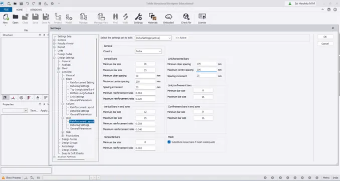
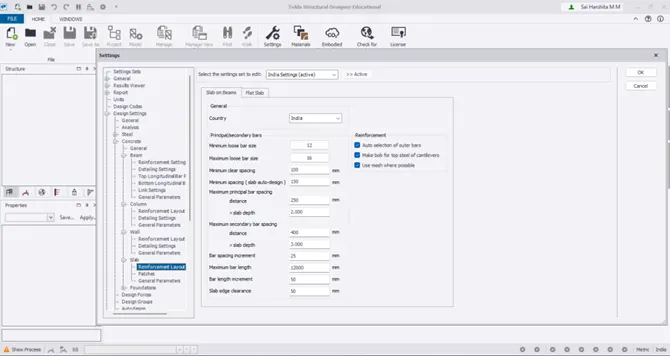
The cover could be adjusted from Settings option in TSD
Procedure:
- Go to Home – Settings
- Under Settings-Structure defaults.
- Adjust the structural default type as TOF/SSL and accordingly adjust the cover
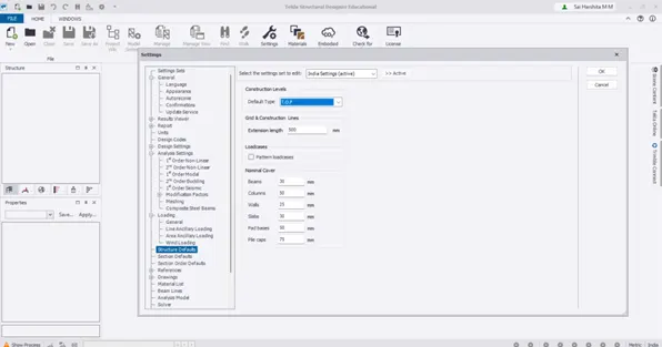
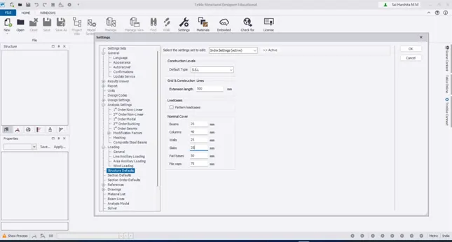
- Also check the Design settings in which the beam and column detailing can be changed
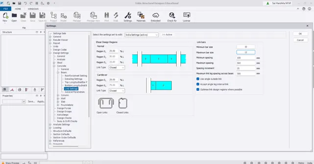
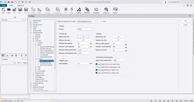
Result:
Thus the model has been setup in TSD
- Model grids as per the attachment 2,2.1 and 2.2
Aim:
To model the grids as per the given attachment
Introduction:
The first step in any modelling is to model the grids horizontally and vertically. Once the grid lines are created, its easy to model beams and columns over the gridlines
Procedure:
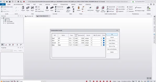
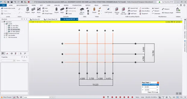
- Go to Model – Construction levels to create 4 levels – Base, GF, FF , RF
- Now go to GF to model the grids by using Model – Grid Line option
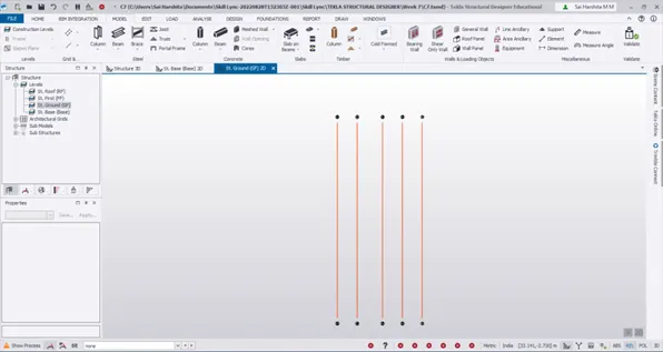
- Use perpendicular grid line option to model horizontal grid line A
- Then go to Model – Dimensions to mark the dimensions between grid lines
Result:
Thus the vertical and horizontal grids are modelled as per the attachment using parallel and perpendicular Grid line options
- Study the layout and write a summary for general arrangement of the structure
Aim:
To study the layout and write a summary for general arrangement of the structure
Introduction:
Reading the structural drawing is very necessary before we start analysing the structure. It helps us take some important Engineering decisions like position of columns,beams etc. It also gives us chance to discuss the necessary changes with the architects so that both aesthetics and safety of the structure is ensured
Procedure:
Ground floor:
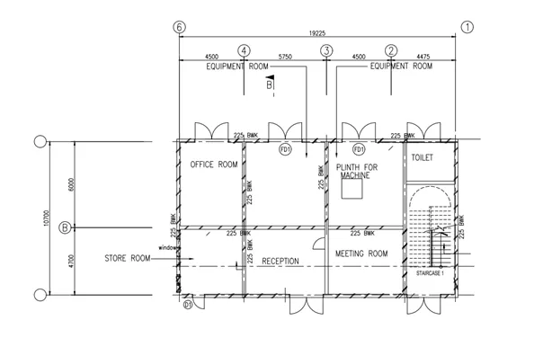
- The height of the GF is 2m form the base
- The ground floor plan is of size 19.225 * 10.7 m
- It comprises of Reception, Meeting room, Office room, toilet, Equipment room and a staircase leading to the first floor
- The columns are modelled in the intersection of the grids
- The spacing between the grid lines are indicated
- The brickwall thickness is mentioned as 225mm
First floor:
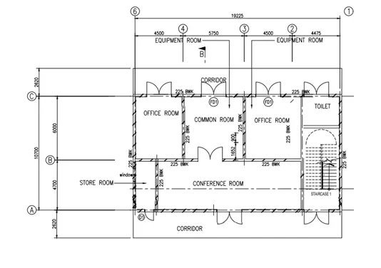
- The height of the first floor from the ground floor is assumed as 3.5m
- The first floor is of same size as that of ground floor except for the corridor on the either side
- The first floor plan comprise of Office rooms, Common room, Conference room, Store room and Toilet
Roof plan:
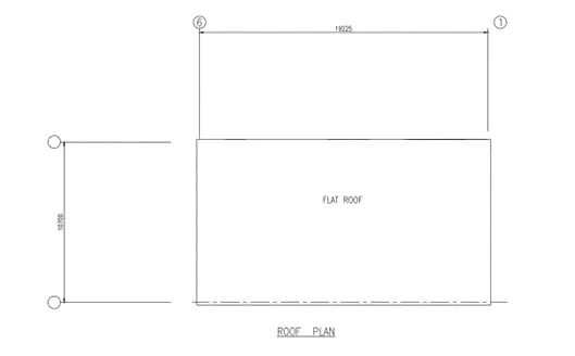
- As we can see above, the roof is a flat roof
- Roof slab is provided to transfer loads to the beams and the beams transfer load to the columns ,columns to foundation and finally to sale
Result:
Thus the structural drawing is studied for various levels of floors, grid spacing, column and beam positioning
4.Model RC columns, beams and slabs as per your general arrangement
Aim:
To model RC columns, beams and slabs as per the given plan
Introduction:
- Slabs are members supporting the floor finishes, equipments and all other live loads including its self weight. They transfer load to the beam. We have primary and secondary beams
- Primary beams are those which transfer load to the columns. They directly rest on columns
- Secondary beams are those which transfer load to another beam necessarily a primary beam. They rest on the primary beams. Secondary beams are provided to break the slab length
- Columns transfer load to the foundation beneath
- The slab,beam and column properties are first created using Manage Property Set. Then they are modelled in the grids
Procedure:
- As we notice in the floor plan, the beams and columns are not exactly placed on the grid line 2. It is at come distance from 2 between 1 and 2
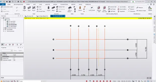
- Go to Manage Property sets and create new concrete column
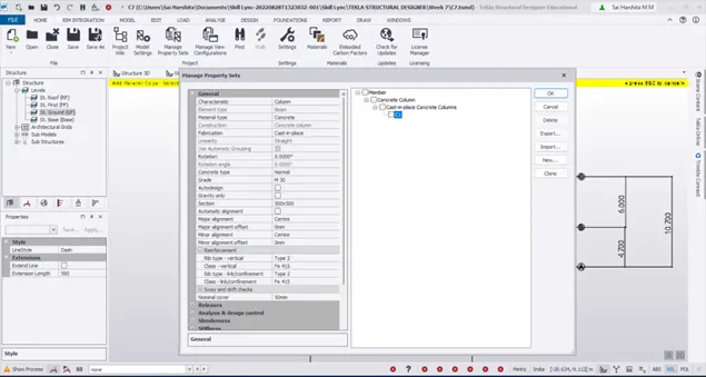
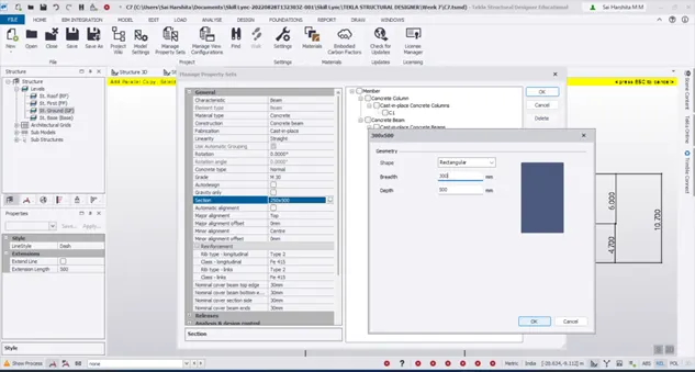
- Now go to Base level and model columns on the grid and construction lines
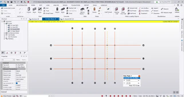
- Then go to Ground floor level and start modelling the beams. Model one horizontal beam and copy paste the beams to the other grids
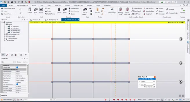
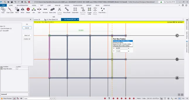
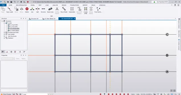
- Now identify the slabs as one way / two way and model them accordingly
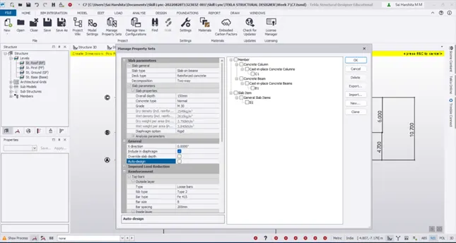
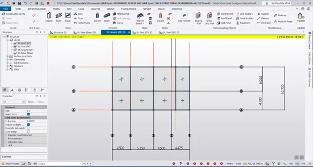
- Now go to FF level and model beams as in GF or from the construction level make the FF and RF level’s source as Ground
- Once the beams and slabs are modelled automatically in FF and RF levels, again go to construction levels to change the source as unique so that corridors can be modelled in FF alone
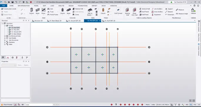
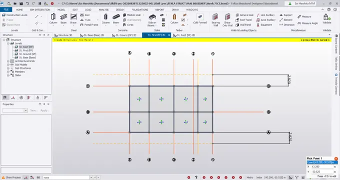
- As seen in the layout, corridors have to be modelled in the FF level
- Model construction lines at 2620mm from the grids C and A
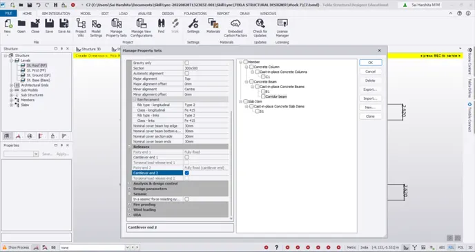
- Now go to Manage Property set to create a new cantilever beam since it’s a corridor.
- Also fix the releases as cantilever end 2
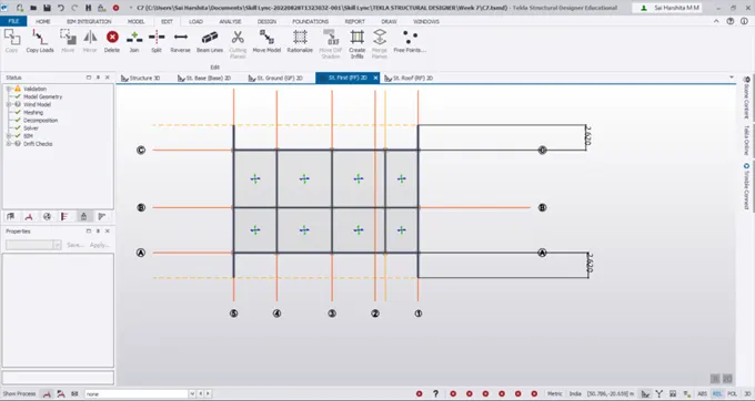
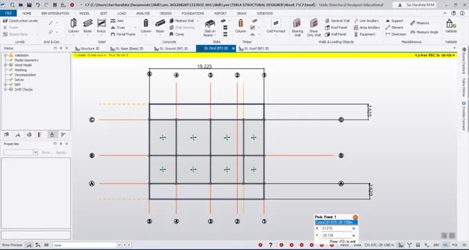
- Now model the corridor as a one way slab
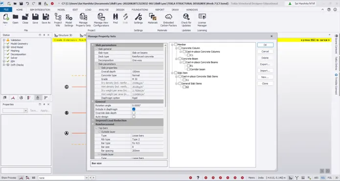
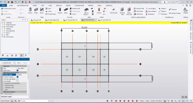
- Validate the model for any errors
- Check the model in Structure 3D
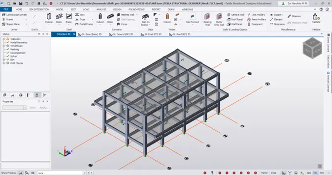
Result:
Thus the RC beams,columns and slabs are modelled according to the sketch