To calculate the dead , live and wind load for RC residential structure and to apply them using TSD
CHALLENGE 9
1.AIM:
To Calculate dead load in design report based on IS code and apply dead load on the model
- Finishes of 50mm
- Slab thickness as per the design
- Brick wall load
- Roofing load
Introduction:
There are 2 broad classification of loads namely Gravity loads and Lateral loads. Loads that act in the direction of gravity are called as Gravity loads and those that act horizontally are called as Lateral loads
Dead load , Live load etc are some examples of Gravity loads and Wind loads, Seismic loads etc are some examples of lateral loads
Dead loads are permanently attached loads of the building. They are the self weight of the components of the structure. Dead load calculations are done using IS 875 Part 1 code book
Procedure:
- Open MS Excel to perform load calculations
- The slab loads are automatically calculated by software
- The floor finishes loads are calculated by multiplying the floor thickness with the unit weight of RCC
- The brickwall loading is calculated by multiplying the wall thickness, height of the wall with the unit weight of the brick. The external and internal wall thickness is assumed as 230mm. The height between 2 floors is assumed as 3.5m
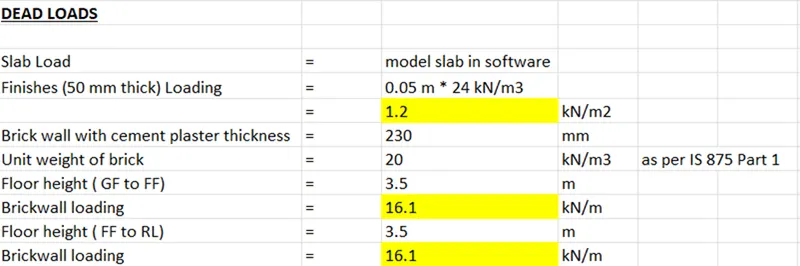
Result:
Thus the dead loads are calculated from the dimensions of the members and unit weight of the material used in the member
2.AIM:
To Calculate live load in design report based on IS code and apply dead load on the model
Introduction:
Live loads are gravity loads that vary with respect to position as well as magnitude. These are the loads due to occupancy, furnitures etc which can be moved from one place to other. Live loads are calculated based on IS 875 part 2
Procedure:
- Open MS Excel
- The various rooms in our structure are listed one by one
- The corresponding live loads are obtained from the IS 875 Part 2 code book
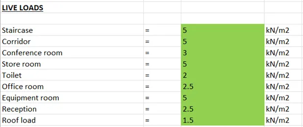
Application of dead and live loads in the model:
Dead loads:
- Go to Load – Load Cases
- Check the load cases
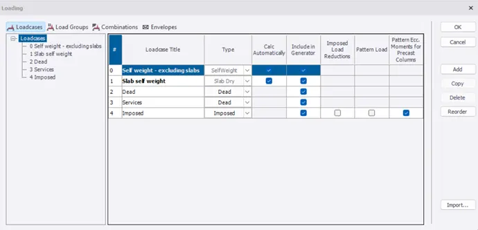
- Select the load as Dead load from the load case below
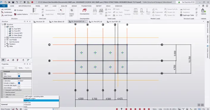
- Refer MS Excel to first apply the floor finish load of 1.2 kN/m2
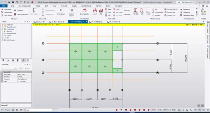
- Repeat the same for every other floor and validate the model
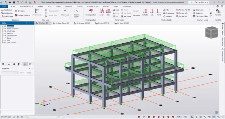
- Now lets apply the brickwall loading to GF and FF
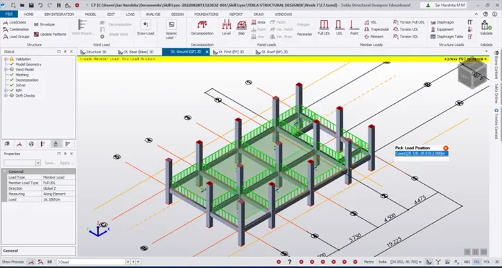
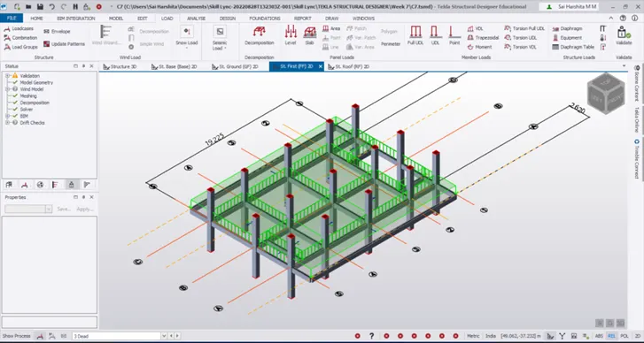
- Validate the model for any errors
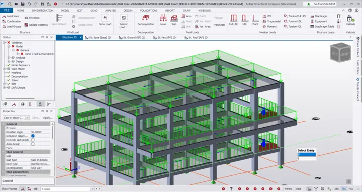
- There is a error stating the panel is not surrounded by members so load distribution could not be carried out.
- Notice that there are no columns below the slab for load distribution. So lets go to the Base floor and draw a construction lines for modelling the columns
- After modelling columns validate once again
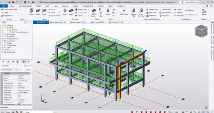
- A warning message ‘Member intersection’ is seen since the beams are modelled before the modelling of those 2 columns. Delete the beams and remodel them to resolve the warning
- Now validate the model again for any errors/warnings
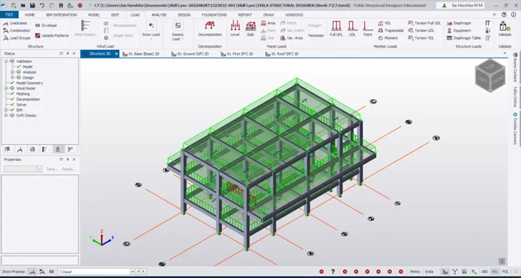
Live Loads:
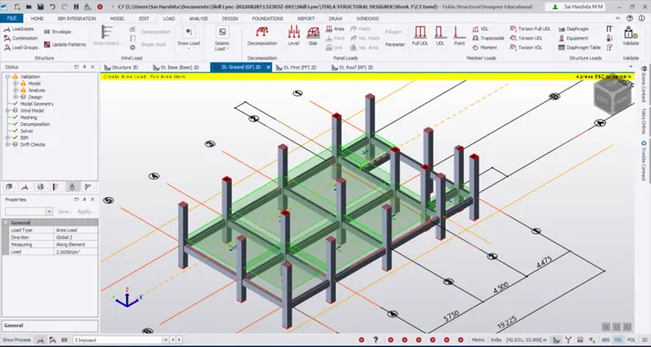
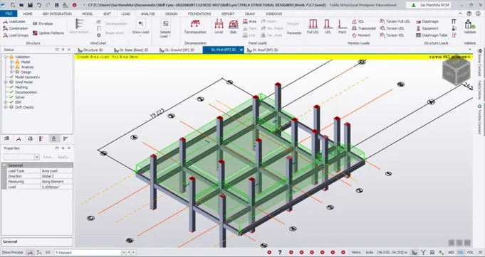
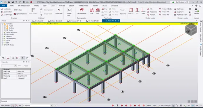
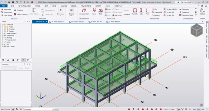
- Now lets apply the imposed load to the model by checking the layout
- Lets first go to GF and apply the loads
Result:
Thus the live loads are calculated as per IS 875 part 2. Dead loads and live loads are also applied to the model
3.AIM:
To Generate manual wind loading in the design report based IS code as per the following input
- Basic wind speed = 50m/s
- Terrain category 2
Introduction:
Wind load is a lateral load acting on the structure. This wind load depends upon the height, location, topography and category of the building. Wind load is obtained from IS 875 Part 3
Procedure:
- Given, basic wind speed , Vb = 50 m/s ; Terrain Category = 2
- Length of the building, l = 19.225 m
- Breadth of the building, w = 10.7 m
- Height of the building, h = 9 m
Step 1: Finding Design Wind Speed:
- Referring to IS 875 P3, Vz = Vb k1 k2 k3 k4 according to Cl 6.3
- Where Vz – Design wind speed
- K1 – probability factor
- K2 – terrain roughness and height factor
- K3 – topography factor
- K4 – importance factor for cyclonic region
- From table 1, k1 = 1
- From table 2, for height of the building 10 m and terrain category 2 , k2=1
- From Cl 6.3.3 , k3 = 1 since, theta < 3(flat terrain)
- From Cl 6.3.4, k4 = 1 for general structures
- Substituting all the above values, Vz = 50 * 1 * 1* 1 * 1 = 50 m/s
Step 2: Finding Design Wind Pressure:
- From Cl 7.2, wind pressure, pz = 0.6 Vz^2
- pz = 0.6 * 50 ^ 2 = 1500 N/m2
- pz = 1.5 kN/m2
Step 3: Design Wind Load:
Wind Load on Wall:
- From Cl 7.3.1, F = (Cpe – Cpi) A pz = Cp * pz
- Cpe is found from Table 5 of IS 875 P3 for h/w and l/w ratios
- h/w = 9 / 10.7 = 0.84
- l/w = 19.225/10.7 = 1.80

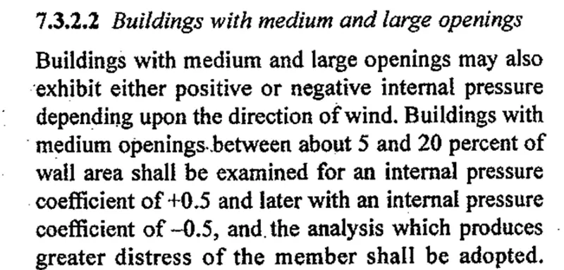
- Lets consider medium openings in which Cpi = + 0.5 / -0.5 according to Cl 7.3.2.2 of IS 875 part 3

Result:
- Design wind speed and pressure are calculated initially
- Then using h/w values and l/w values, the Cpe values are found for wind angles 0 and 90 for all 4 sides
- Cpi values are assumed
- For + Cpi and – Cpi , the various values are worked out and design wind loads are found for walls
4.Aim:
To apply the loadings on the model based on the above loadings
Introduction:
Based on the above generated loads, the load cases are created first viz,
- Wind + Y + Cpi ( A – windward, B – leeward)
- Wind + Y – Cpi
- Wind + X + Cpi ( C – windward, D – leeward)
- Wind + X – Cpi
Procedure:
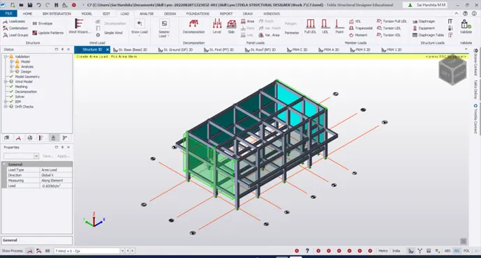
- For application of wind loads, its necessary to model wind panels
- Hence frames are created from Model – Frame
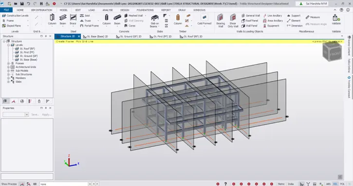
- Pick end frames and model wind and roof panels
- Model – Wall panel
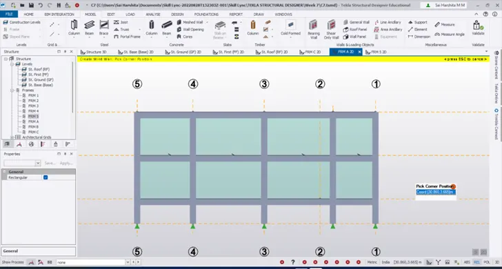
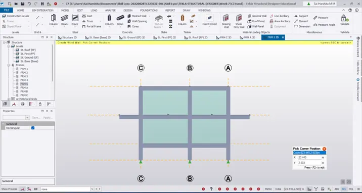
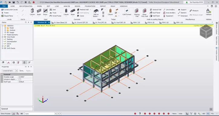
- Now lets start applying the wind loads in faces A,B,C and D
- Load – Load cases – Create 4 load cases for wind load
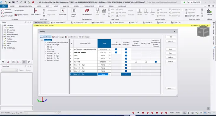
Wind + Y + Cpi:
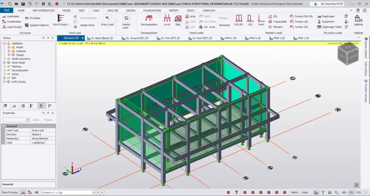
Wind + Y – Cpi:
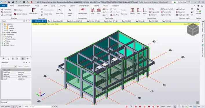
Wind + X + Cpi:
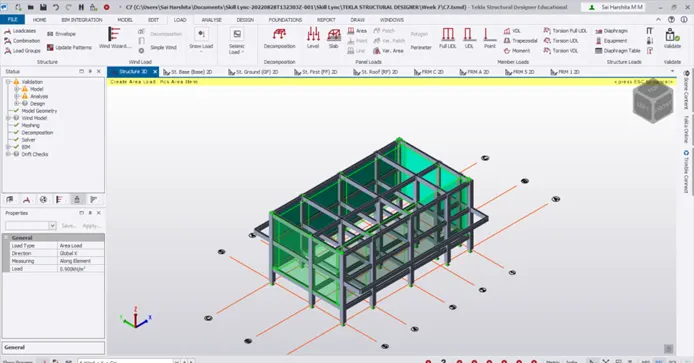
Wind + X – Cpi:
Result:
The various load combinations +Y + Cpi, +Y – Cpi , + X +Cpi and +X – Cpi are thus applied on the model