To Generate seismic loading based on IS code and to run the analysis using TSD
CHALLENGE 10
1.AIM:
To Generate seismic loading based on IS codal provisions and zone II.
Introduction:
Seismic loads are the lateral loads acting horizontally in a building. The seismic loads act in 2 horizontal directions. Seismic loads lead to ground shaking and the building vibrates in its horizontal directions and eventually collapses. So its very important to consider seismic loads in buildings of seismic prone areas
India is classified into 4 zones 2,3,4 and 5. The zones 4 and 5 fall into the risk category. So the buildings in those zones are to be designed considering seismic loads
Procedure:
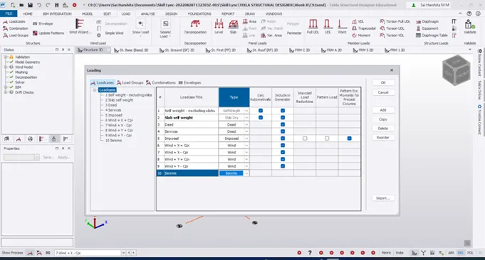
- Load – Load cases . Add seismic load in the load case window
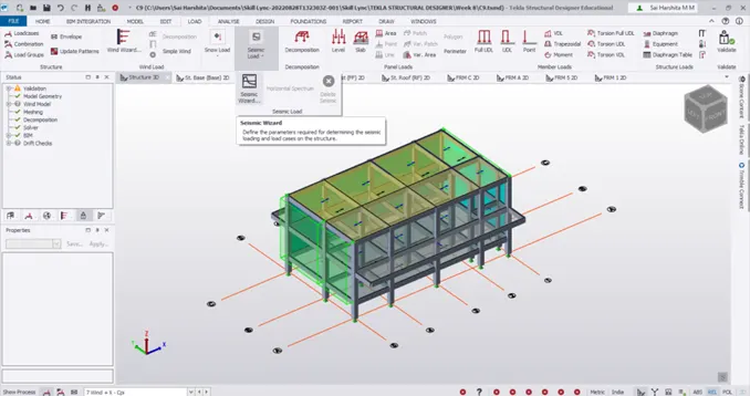
- Now go to Seismic Load – Seismic wizard
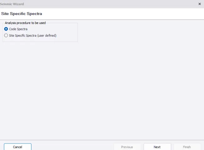
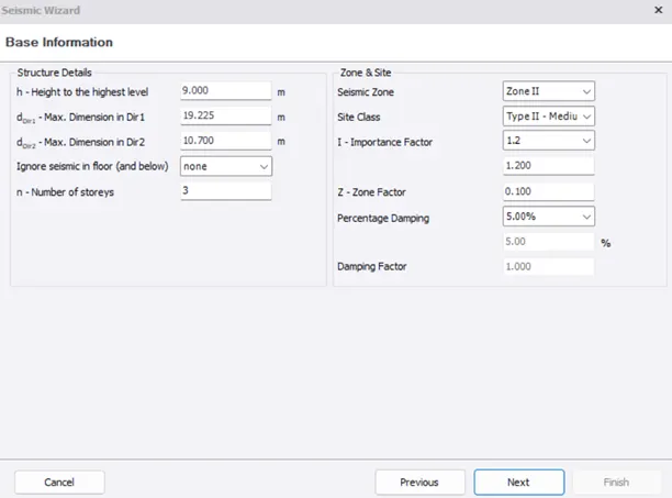
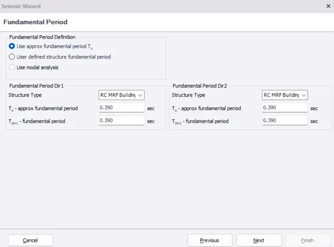
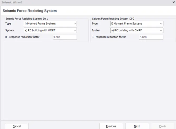
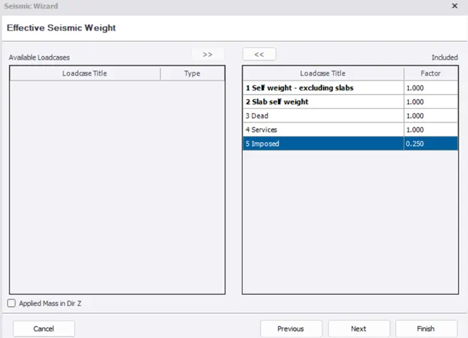
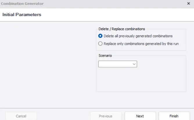
- Click Next and Finish to generate the load combinations
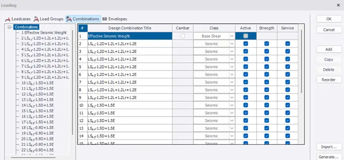
- Now we can see that all seismic load combinations are generated
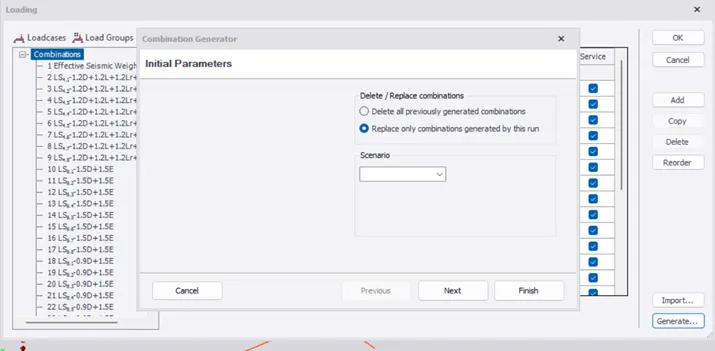
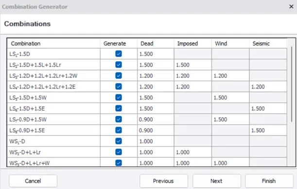
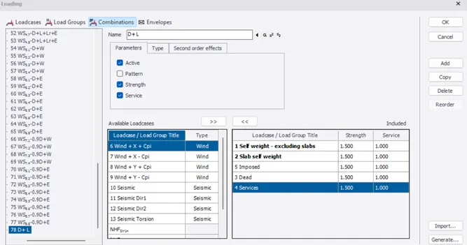
- For generating other combinations for gravity and wind loads, click on generate
Result:
Thus the seismic loads are applied and the load combinations are generated
- AIM:
To run the analysis and summarize the understanding of the analysis results
Introduction:
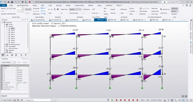
BMD(Bending moment diagram ) is a diagram representing the variation of bending moment along the length of member .
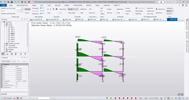
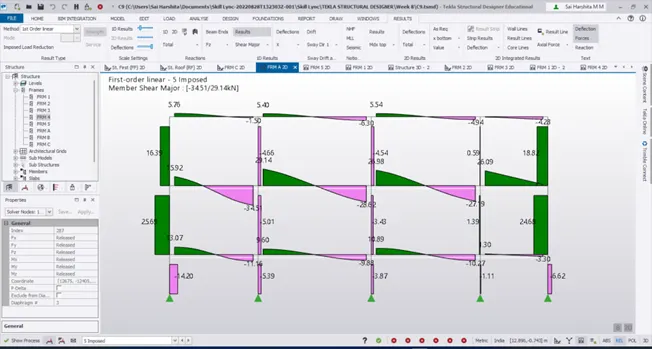
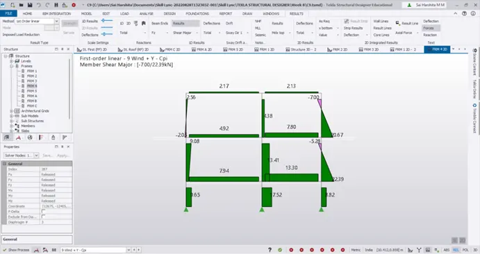
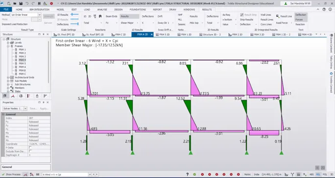
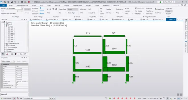
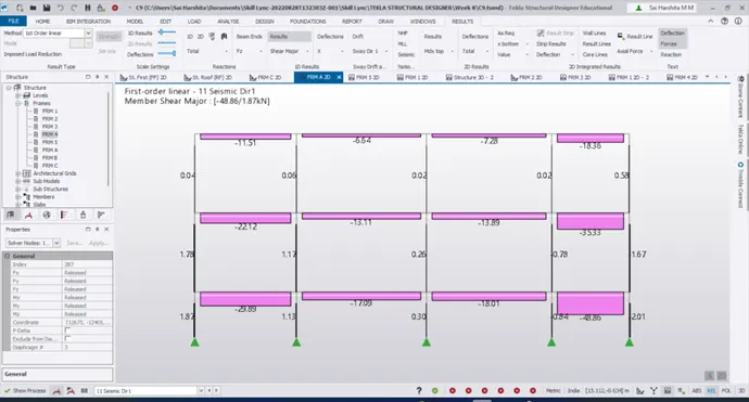
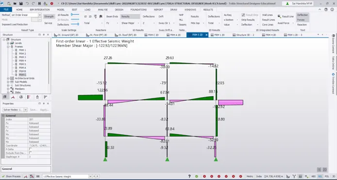
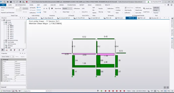
SFD(shear force diagram ) is diagram representing variation of shear force along the length of structural member .
Deflection also referred to as displacement, which can occur from externally applied loads or from the weight of the body structure itself. Deflection diagrams give the values of deflection at various points in the structure
These diagrams are very much necessary since it helps us understand how much stress a particular member is expected to bear according to which the design of that member could be done
Procedure:
- Go to Analysis – First order linear analysis
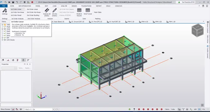
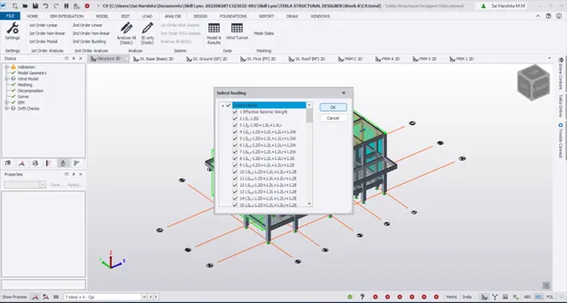
- Select all the load combinations for which the analysis is to be run
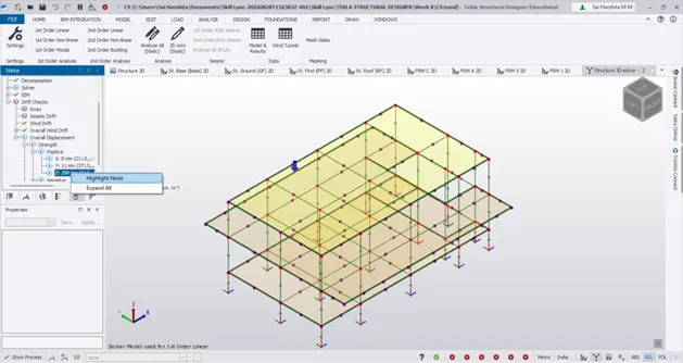
- Go to overall displacement to check the node with maximum displacement
- Now go to Deflections – Z in Results view
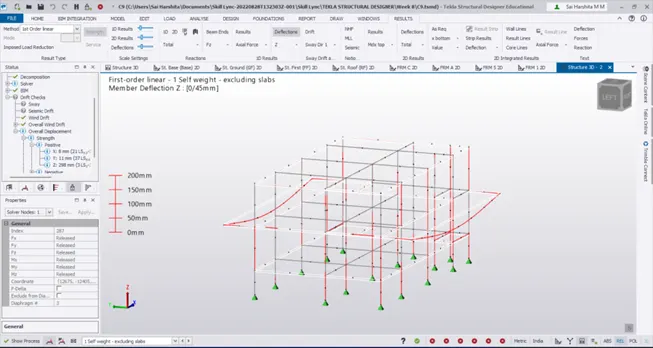
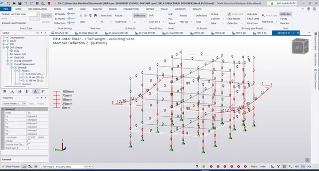
- Notice that the maximum deflection occurs in the corridor portion which means we need to add more secondary beams to the corridor
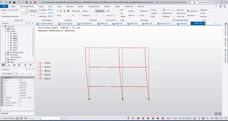
- Following is the deflection due to wind load
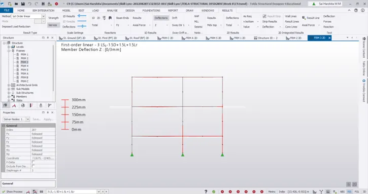
- Following is the deflection due to gravity load case
- Notice the maximum deflection occurring in the cantilever end
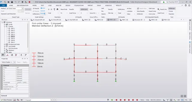
- Check the deflection in the other frame direction too
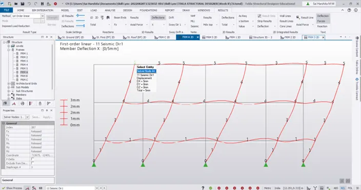
Axial force diagram:
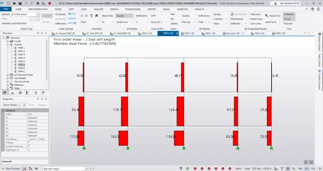
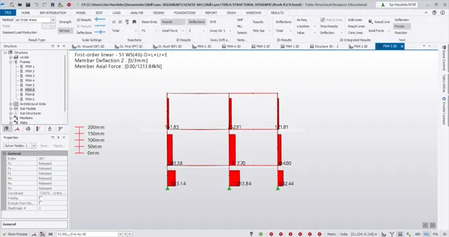
- Notice that the Axial forces increases as we move down the floor
Shear force diagrams:
Shear force due to gravity loads:
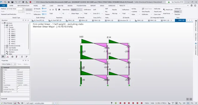
Shear force due to wind loads:
Shear force due to seismic loads:
Bending Moment Diagrams:
BMD under wind loads:
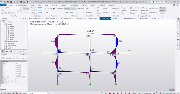
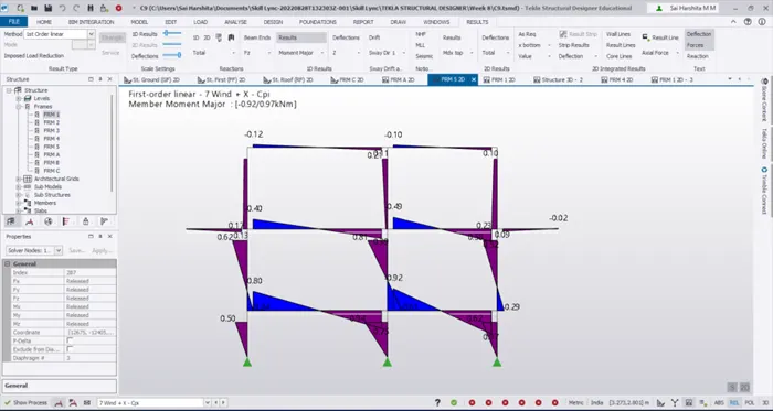
BMD under seismic load:
BMD under gravity loads:
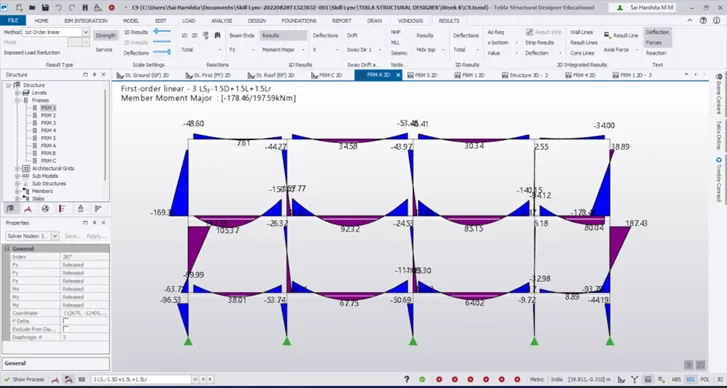
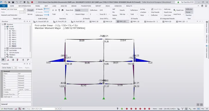
Observe that the bending moment is zero at the cantilever end
Result:
Hence the analysis results were summarized and interpretations were made