To Design RC column and beam for RC residential structure using TSD
CHALLENGE 11
- Based on the analysis design RC column and beam.
Aim:
To design RC column and beam based on the analysis
Introduction:
Analysis is carried out by assuming the preliminary sizing of the members. Then check for members is carried out to find the members that have failed the design criteria. Resizing the members, changing the number, diameter and layer of reinforcement is carried out to pass the member
Procedure:
- Launch Tekla Structural Designer
- Select Frame A
- Lets interactive design each of the columns and beams in frame A
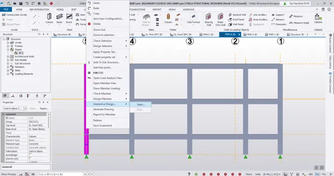
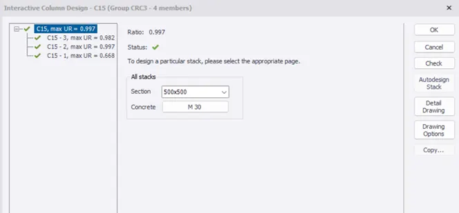
- Notice that the utilization ratio for stacks 2 and 3 are much high. So the design has to be changed
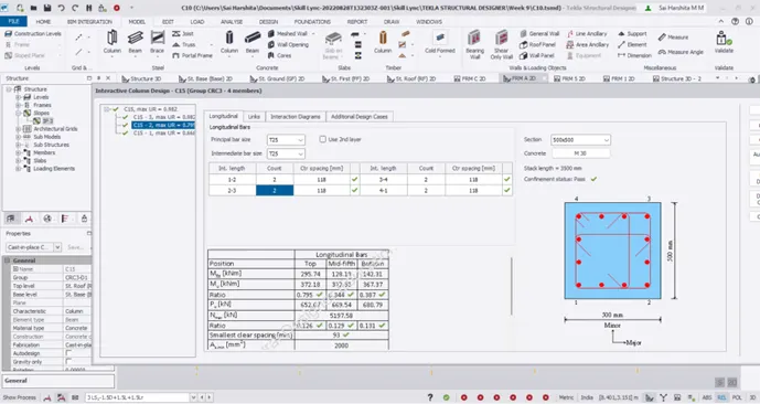
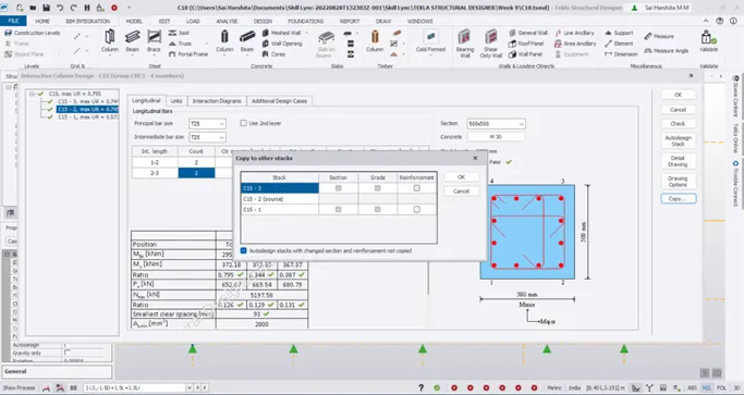
- Change the no of intermediate reinforcement to 2 and copy the same to the other stacks too
- Now select the other exterior column and change the reinforcement as the previous column
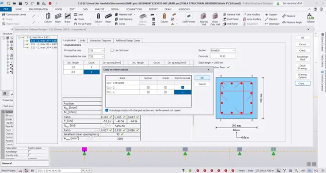
- Now check the interior columns and notice that the utilization ratio are well within limits
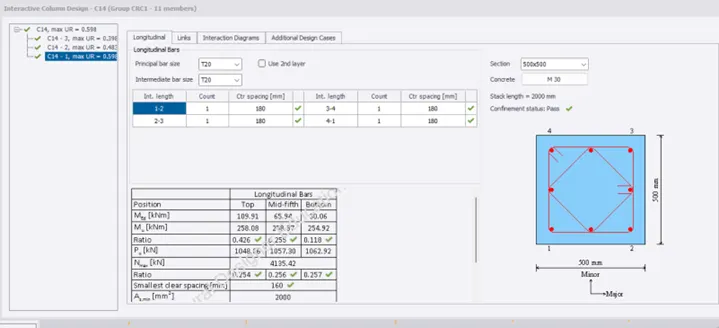
- Now select the centre column in grid 3 and notice that its safe and has passed the design criteria
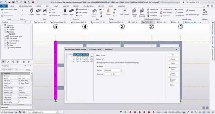
- Also check beams in frame B
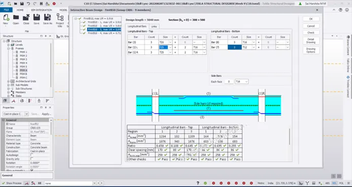
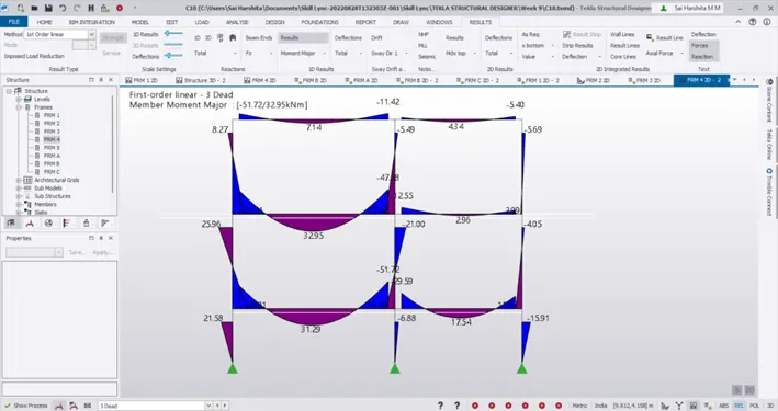
- We can also check the BMD for the beams and identify and design beams with the large bending moment
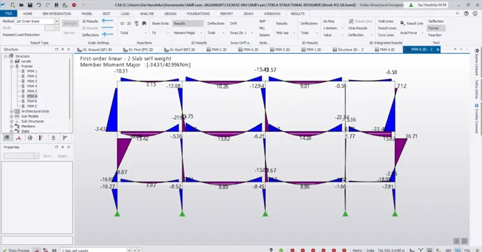
- The beams in second stack is then designed
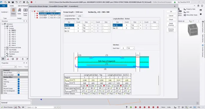
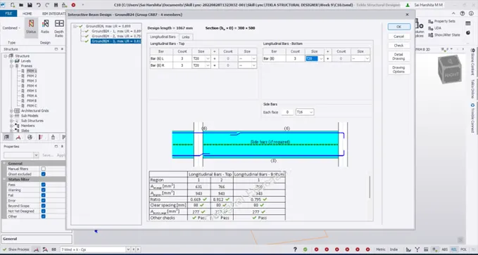
- Also notice that the ground floor beams have failed
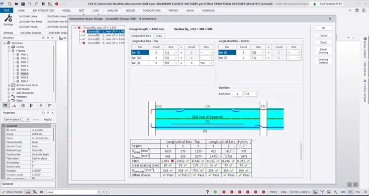
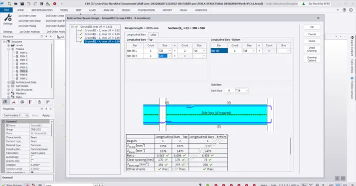
- Increase the bar diameter to pass the member
- Now review the beams of the frame
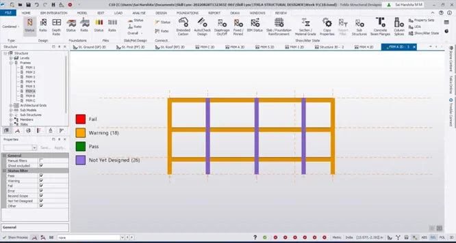
- Now select Frame B and perform interactive design
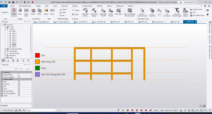
- Similarly perform interactive design for frame C
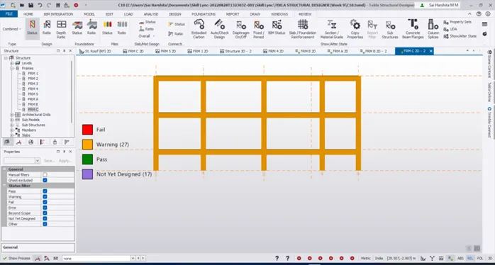
- Check the frame on the other side
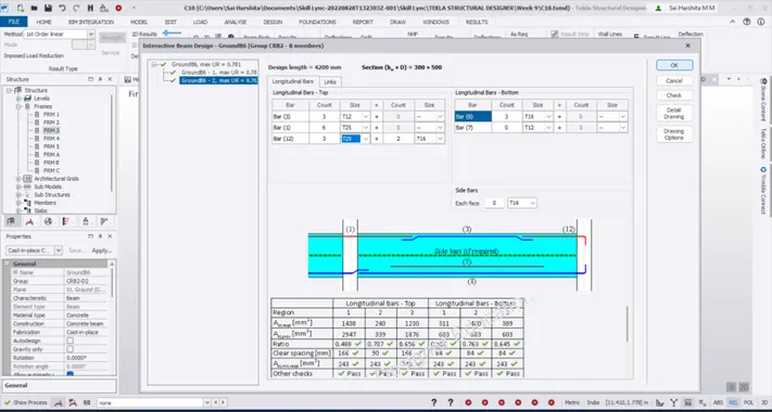
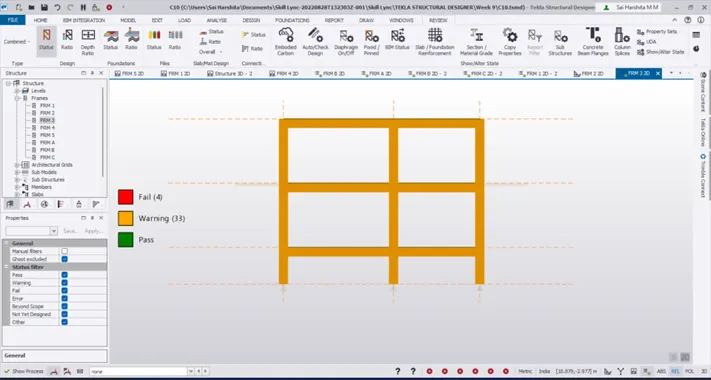
- On checking Frame 5, we notice that it fails at the cantilever ends
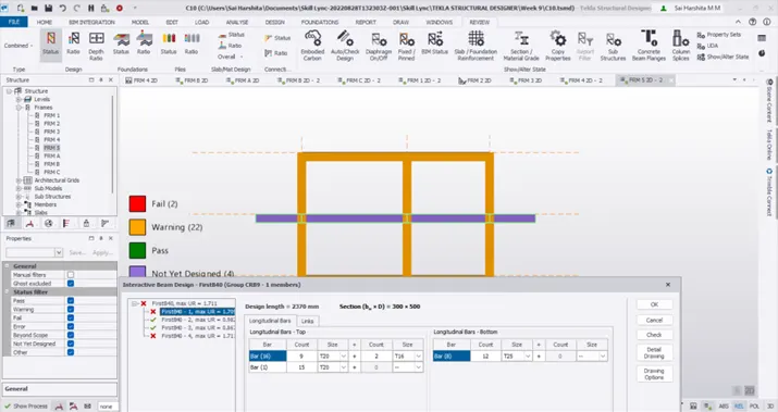
- Notice that even when the diameter of bars and no of bars are increased the cantilever portion fails which means that additional secondary beams need to be provided
- Model secondary beams in the corridor region of first floor and model slab on it
- Apply dead and imposed loads
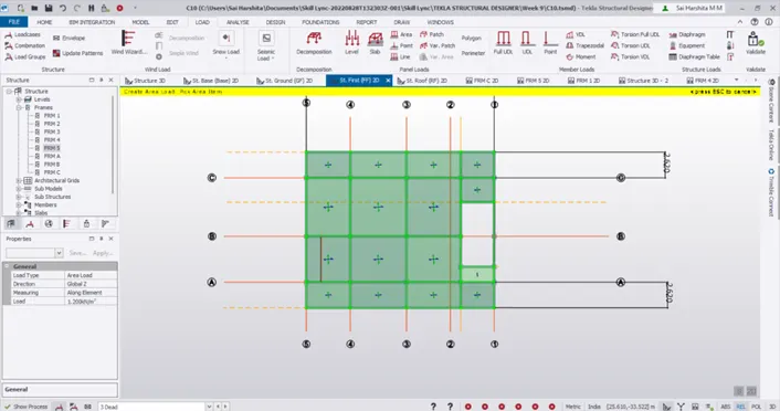
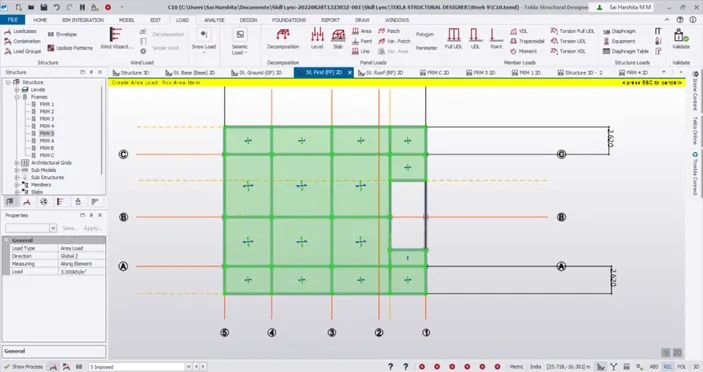
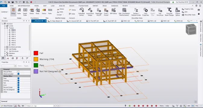
- View the structure in 3D
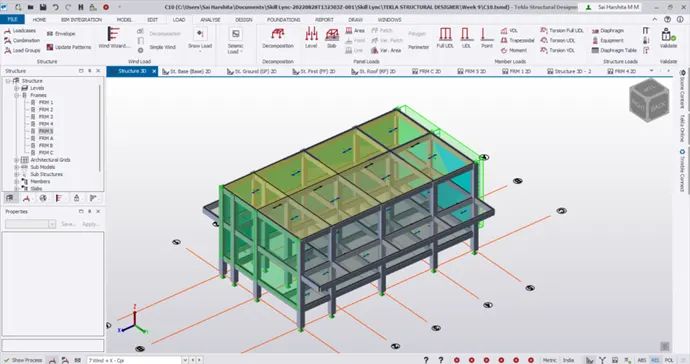
- Now check the beam again
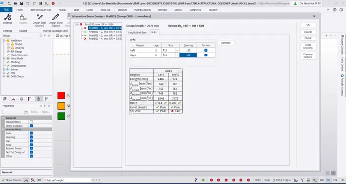
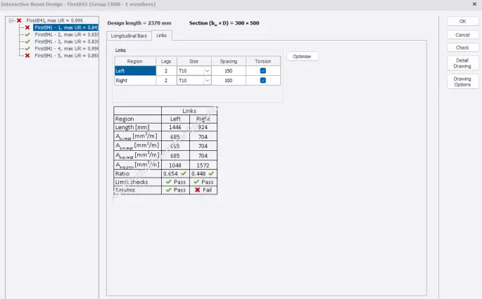
- Notice that the error is not resolved yet
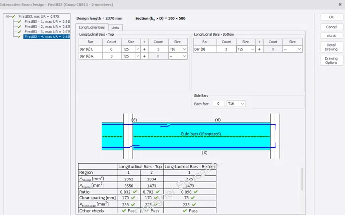
- Click on Check button to check where the 1st and 4th member fails
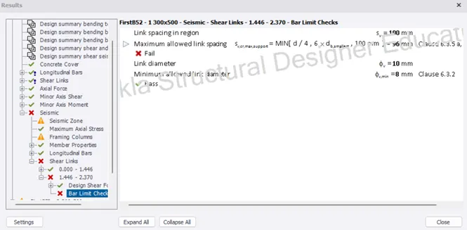
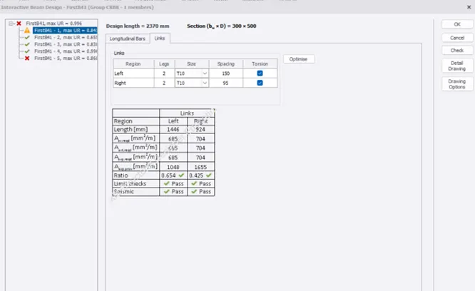
- Observe that the maximum link spacing allowed is 96mm. So we need to amend our link spacing to 95mm
- Before that make sure that in the link settings, the minimum spacing is entered as 90mm from the Design – Settings
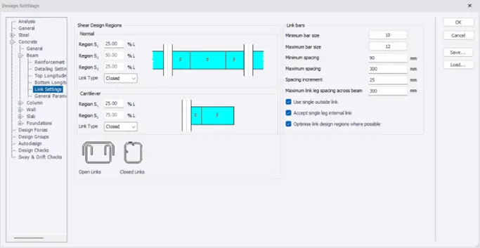
- Now select the member and in interactive design, change the spacing to 95mm
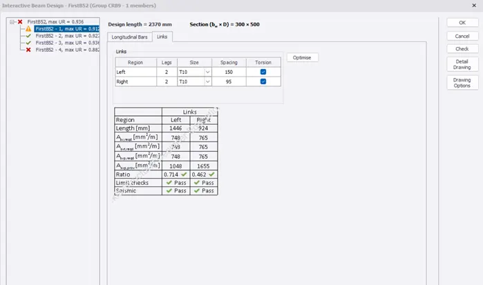
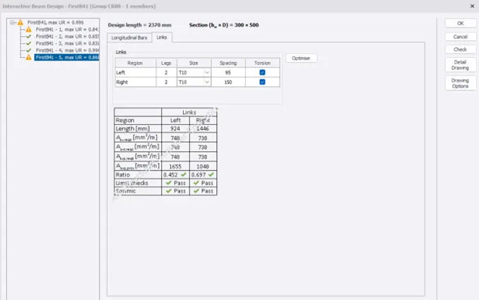
- Similarly check the 4th member and change the spacing to 95mm accordingly
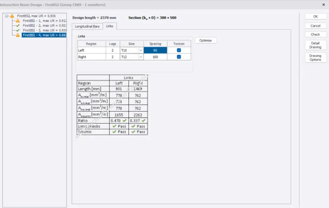
- Now review the member
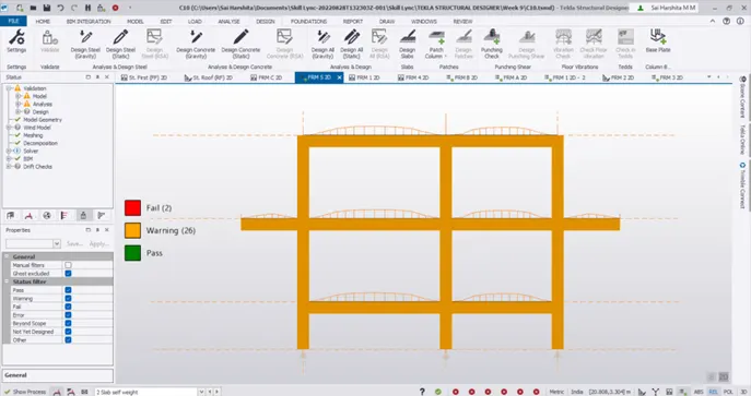
- Similarly go to Frame 3 and do the checks
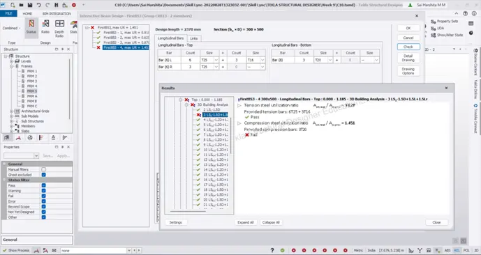
- Increase the diameter of the compression bars to pass the member
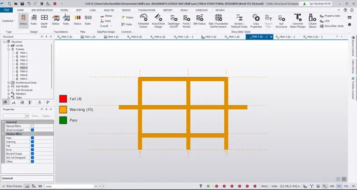
- Go to Structure 3D and review
- Identify the members that have failed and redesign
- Also check the remaining members that are not yet designed
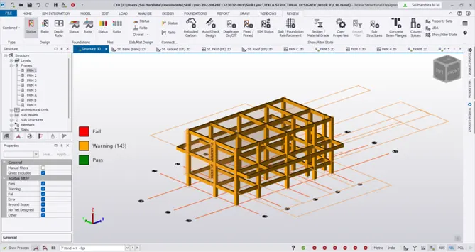
Result:
Thus the interactive design of RC beams and columns have been carried out based on analysis. The number, diameter and spacing of bars can be changed subsequently after check