Week 8 Challenge
WEEK 8 CHALLENGE SOLUTIONS
1. AIM:
Applying Load Exercise
For the structure modelled in previous exercise. Apply following loads
- Form a Load case as DL for Dead Load
- Apply Self weight
- Apply member load of 3 kN/m on the rafter
- Apply member load of 6 kN/m on the secondary beams
- Apply point load of 20 kN at node intersecting inclined member on the top chord.
- Form a Load case as LL for Live Load
- Apply member load of 4 kN/m on the rafter
- Apply member load of 7.5 kN/m on the secondary beams
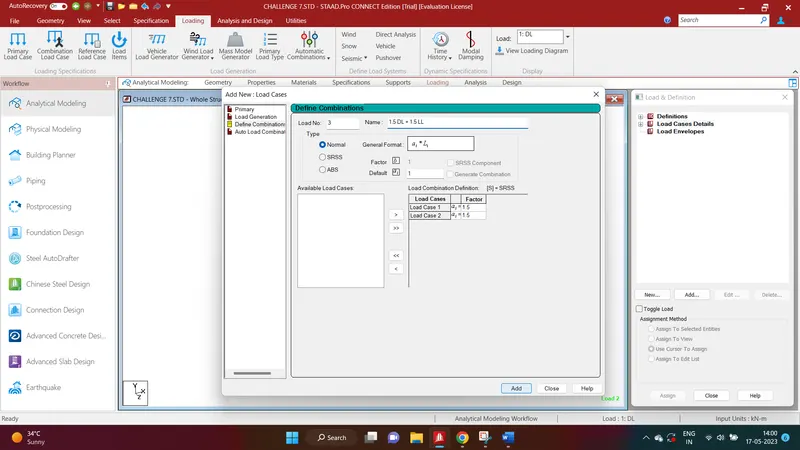
- Form load combination 1.5DL+1.5LL
Procedure:
Open the previous challenge
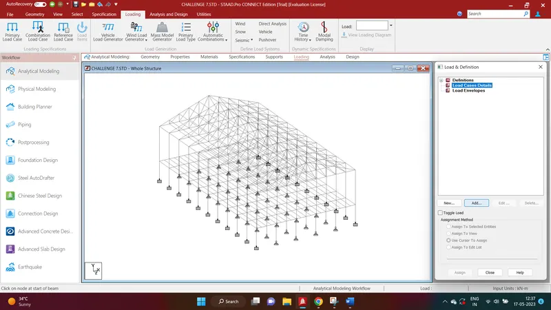
- Go to Loading tab and select Load Case Details.
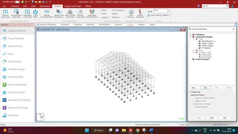
- Then click Add, Select Dead load and name it as DL as shown below.
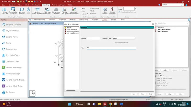
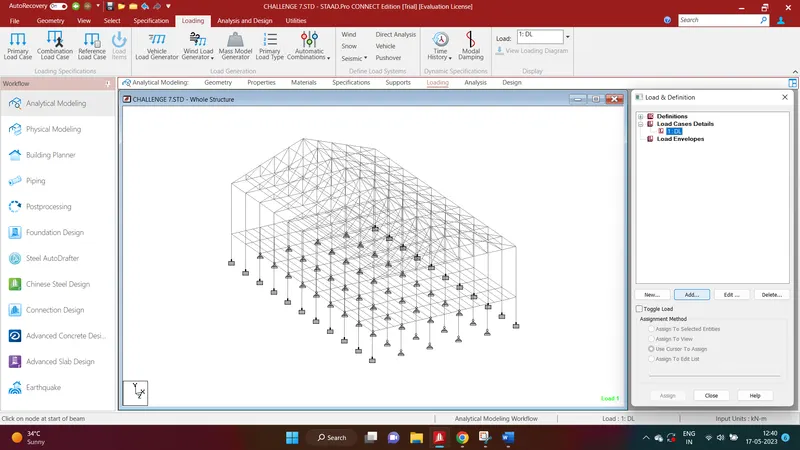
- Now select DL load case, and click Add.
- Then click Selfweight Load and give -1 factor of load at Y direction.
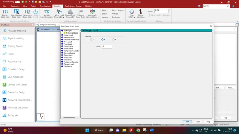
- Now select Member Load, then give input as -3 kN/m for Rafter and -6 kN/m for Secondary beams along GY direction.
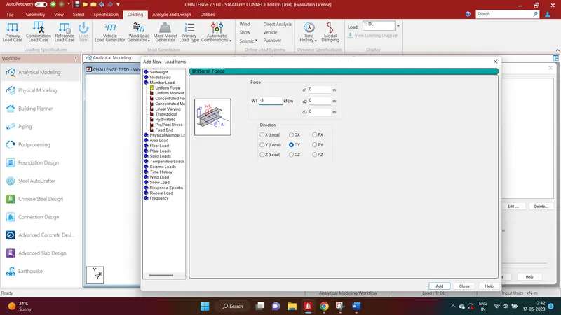
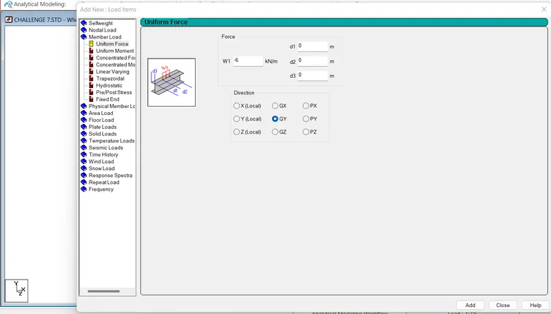
- Then select Nodal Load, give input as -20 kN.
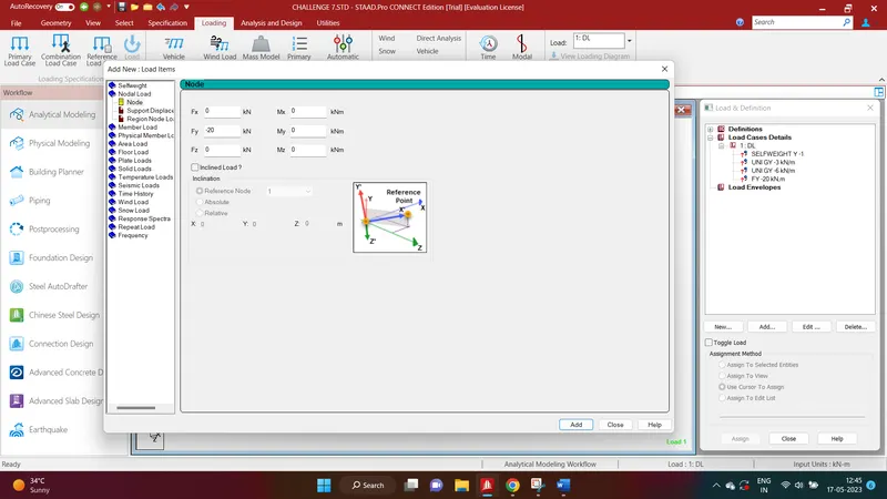
- Assign all Dead Load to the structure as shown below.
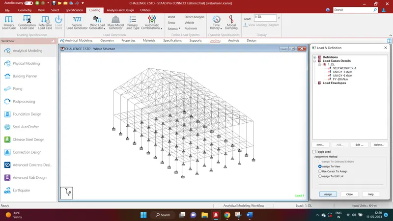
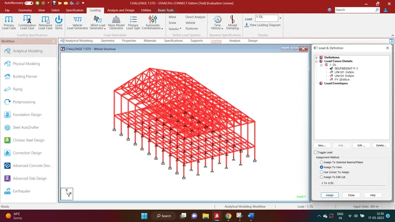
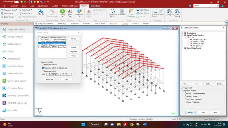
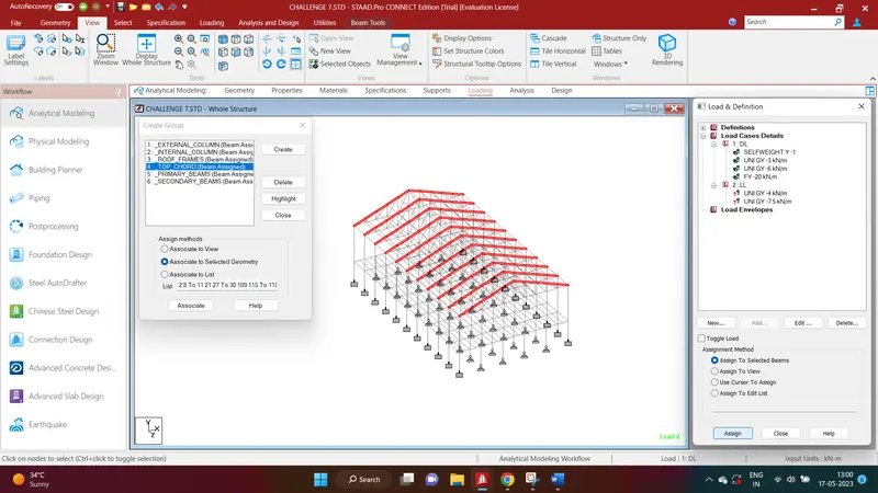
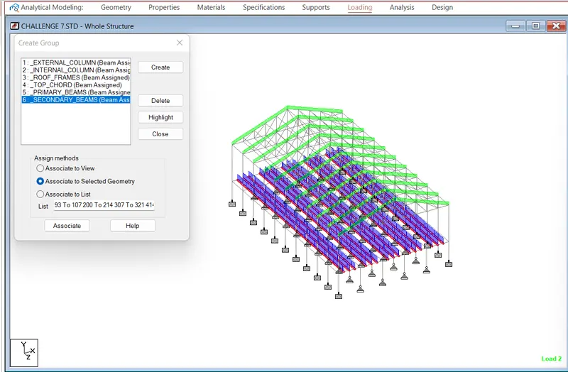
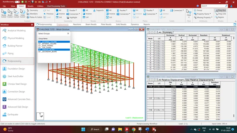
Go to Utilities - Groups. Highlight the top chord/rafter
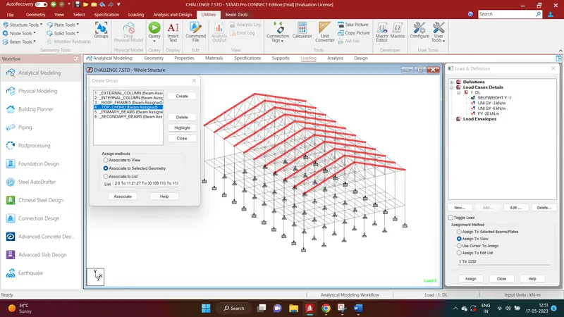
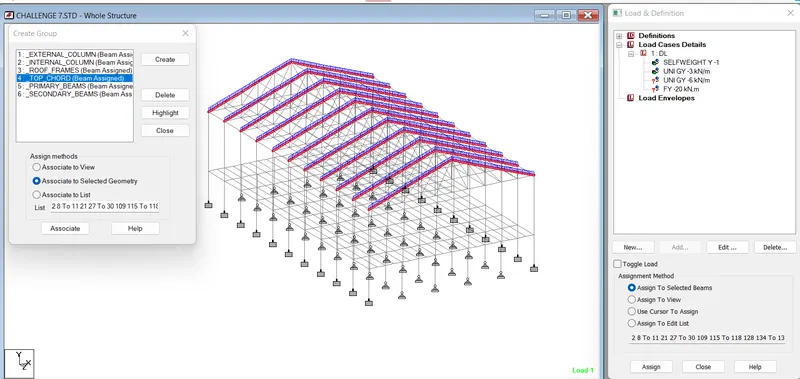
Now assign the member load of 3kN/m to the rafter
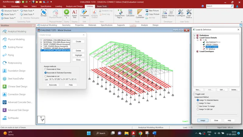
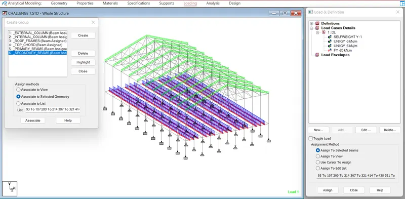
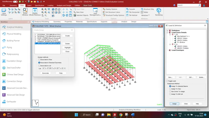
Highlight secondary beams from Groups and assign -6kN/m on it
To assign nodal load of 20kN go to nodes cursor and select the required nodes
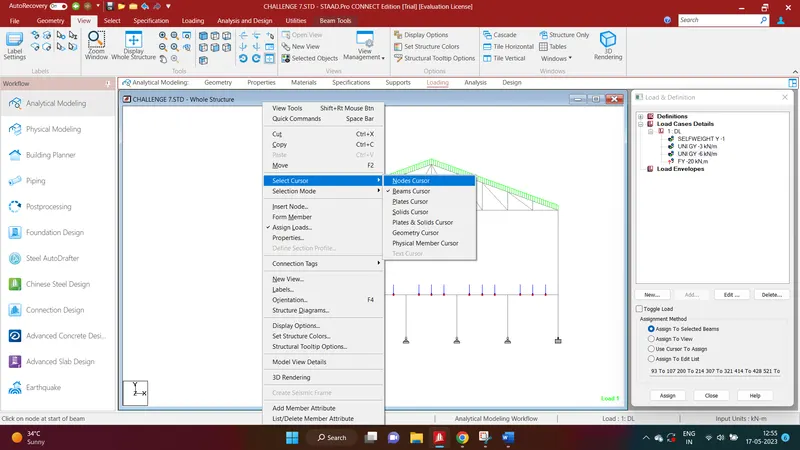
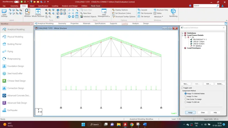
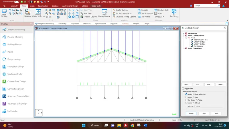
- Again add Load Cases Details as Live Load and name it as LL.
- And add -4 kN/m and -7.5 kN/m of Member Load for Rafter and Secondary beams respectively.
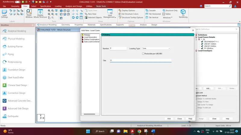
Now click on LL and start adding member loads in it
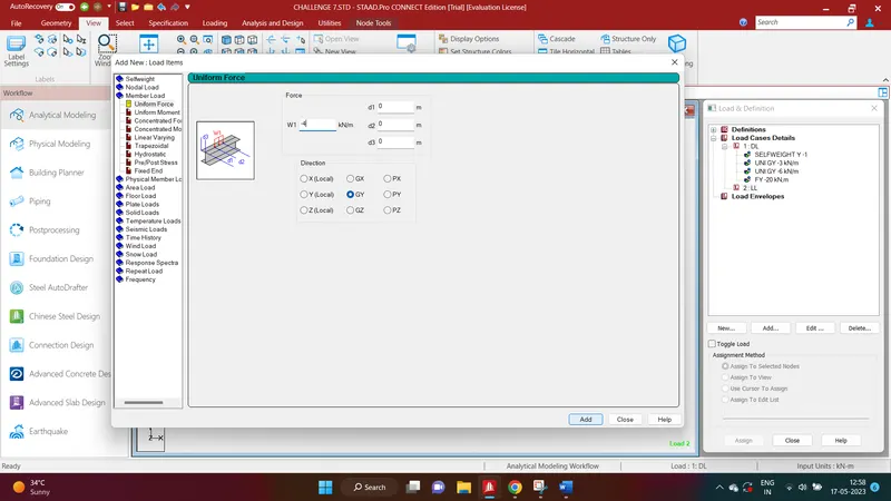
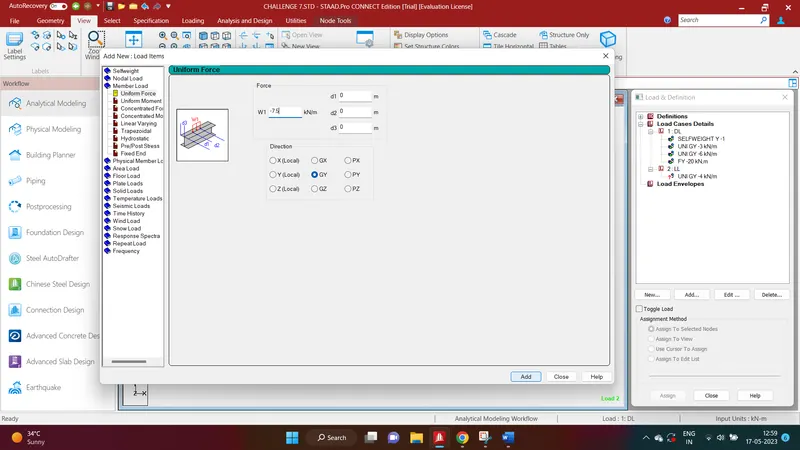
Utilities - Group. Highlight top chord / rafter members
Click on Add to define the load combinations
2. AIM:
Find Maximum Force and Minimum Force for member and present the STAAD result.
Continue previous challenge, Run the analysis and find following results on the member mentioned
- Run the analysis
- Find the Maximum Moment in the Secondary beam for 1.5DL+1.5LL case
- Find the Maximum Axial force on the inclined bracing and identify the member having the maximum force for 1.5DL+1.5LL case
- Identify Bottom chord of Truss having Maximum shear Force & Maximum moment for 1.5DL+1.5LL case and present the values.
Procedure:
Go to Analysis and Design - Define Commands
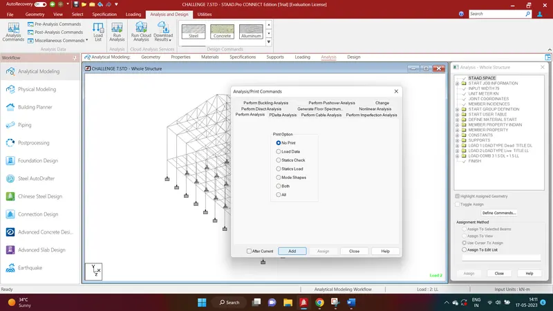
- Then click Run Analysis.
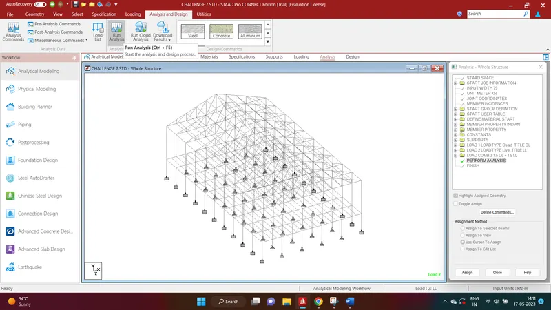
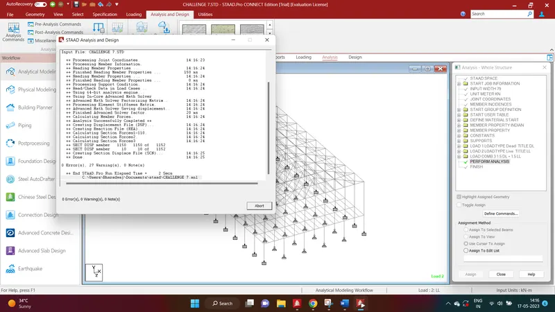
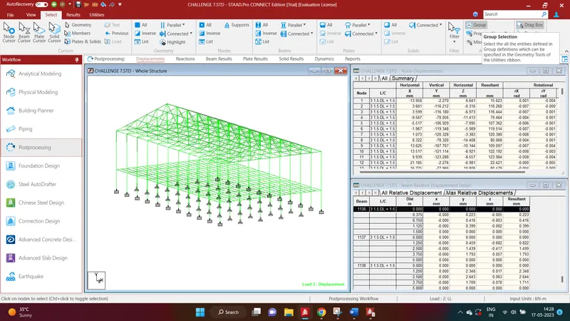
- Now select Postprocessing to see the Results.
- Then choose the Load Combinations.
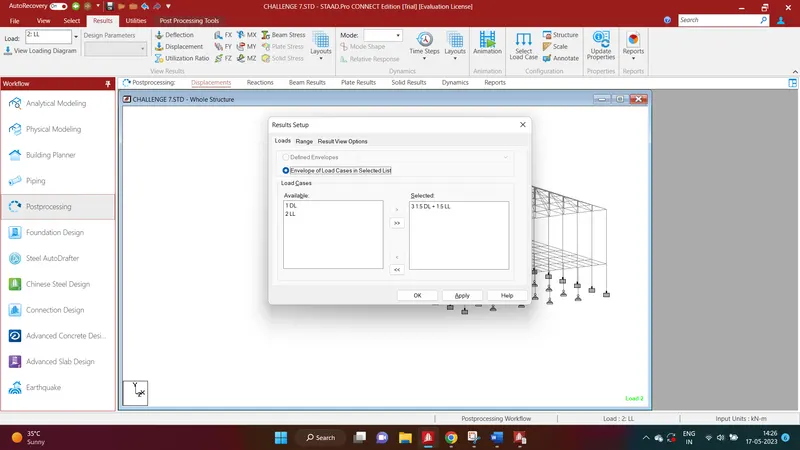
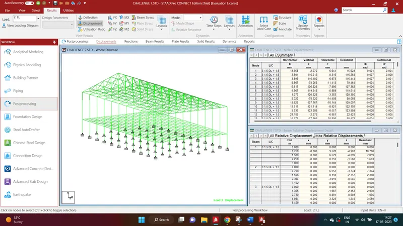
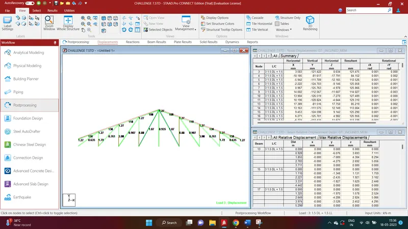
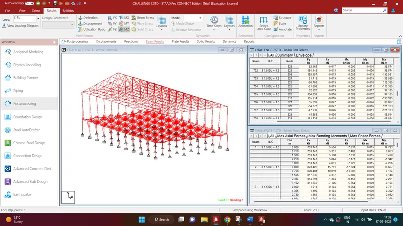
Click on Beam results to view the bending moment
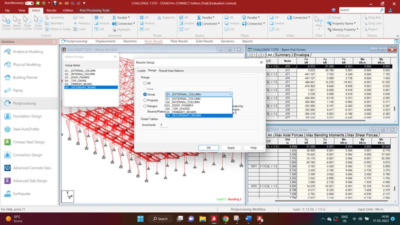
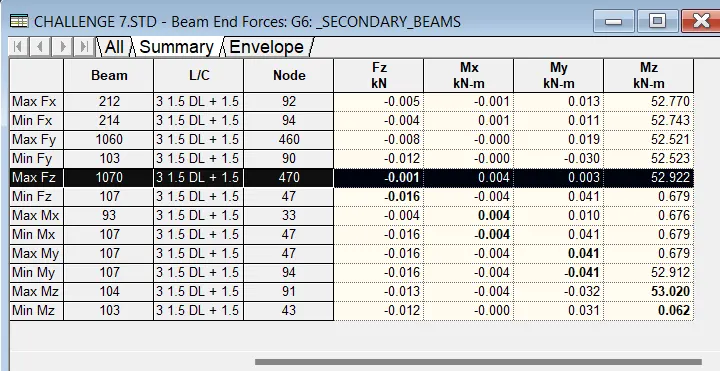
The maximum moment for 1.5DL + 1.5LL is 52.922 kNm
Now view the BM results of the inclined bracings
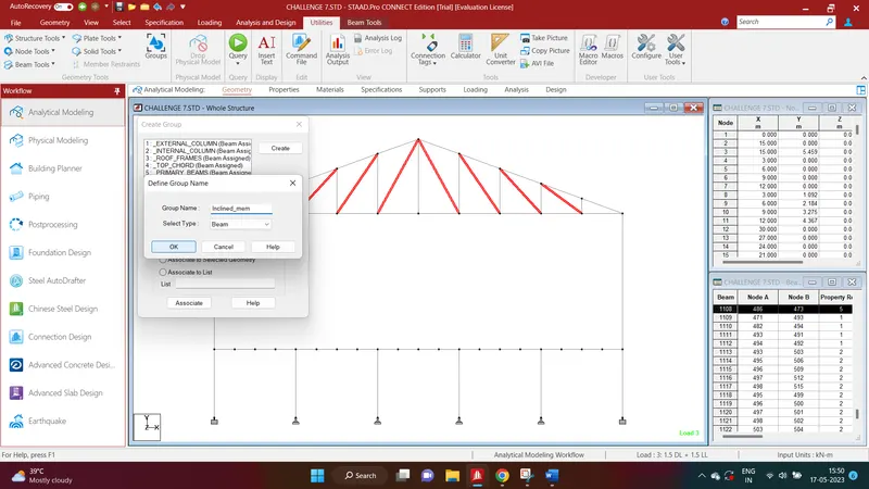
Create a group in the analytical modelling for inclined members
Click on Mz in the View Results. Annotate - Choose member in the group
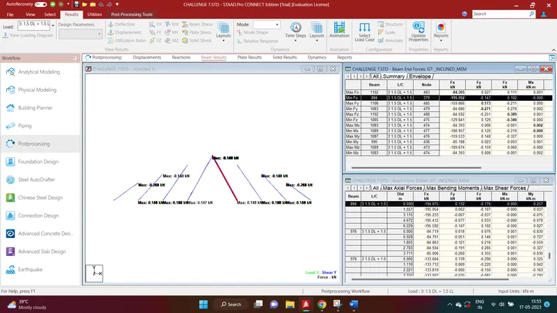
Right click on the table - Results Setup- Group
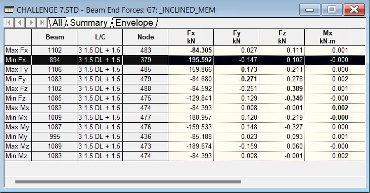
Similarly view the axial forces
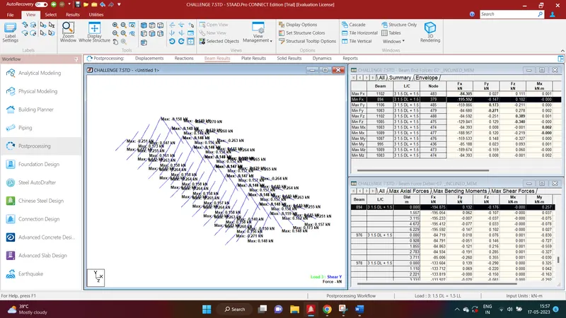
Now view the max SF and BM for bottom chord under the load combination
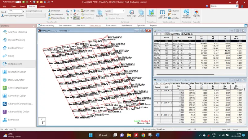
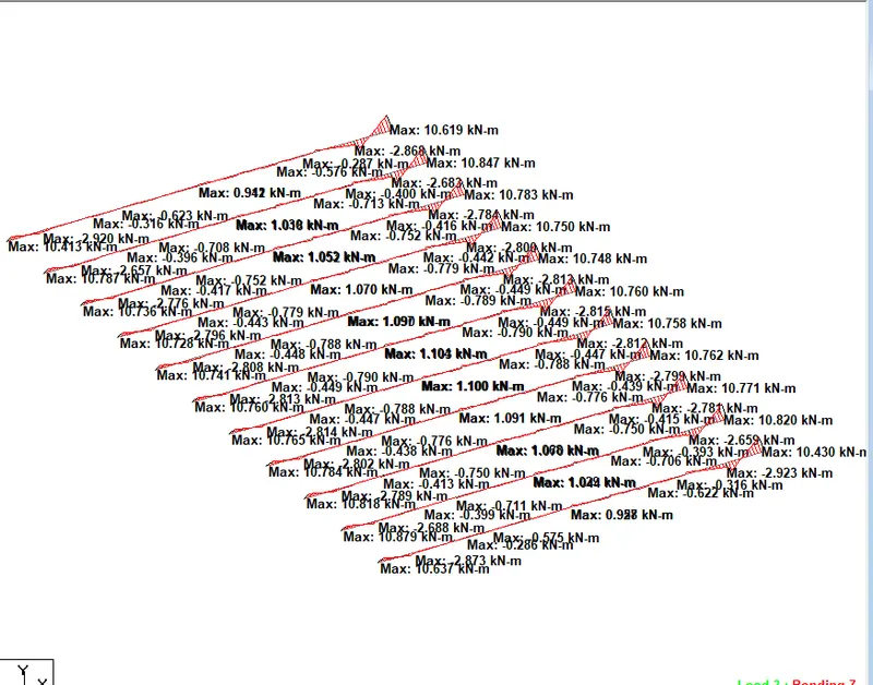
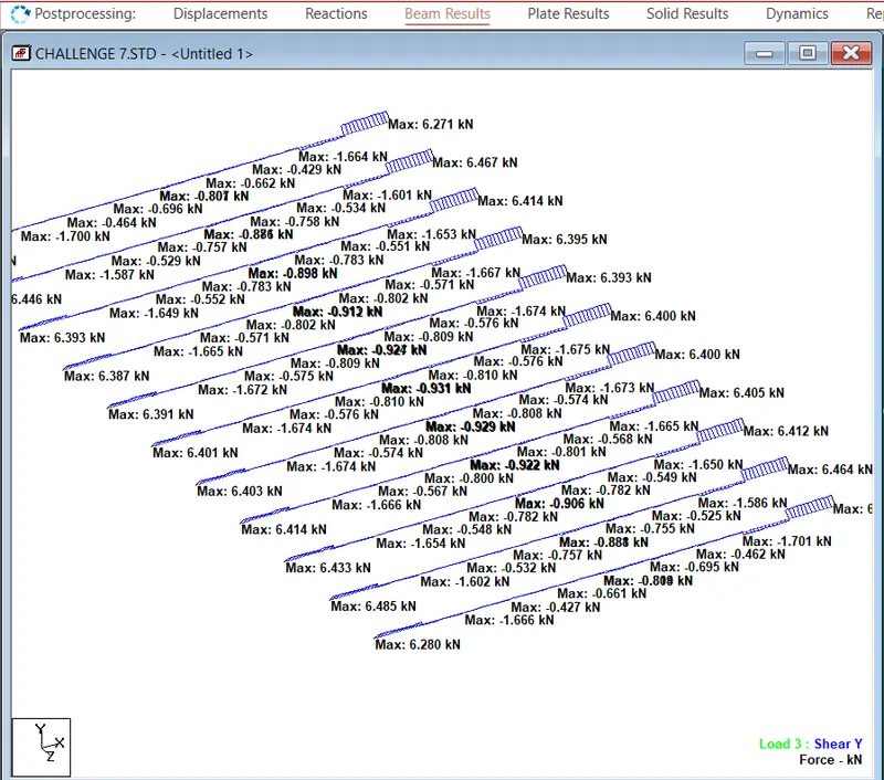
3. AIM:
View and Rectify the Warning, instabilities in the structure
For the attached STAAD file identify the Warnings and fix the same and run the analysis.
Procedure:
- Open the STAAD File given in the attachment.
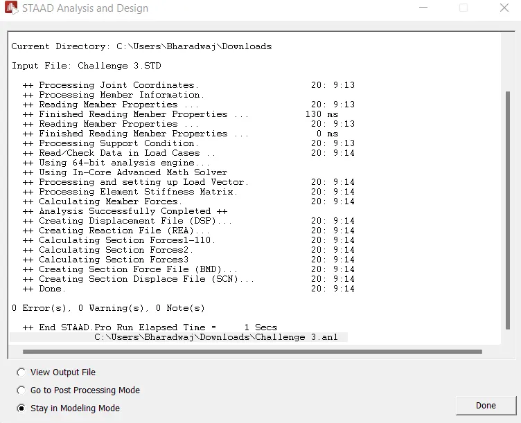
- Run the analysis
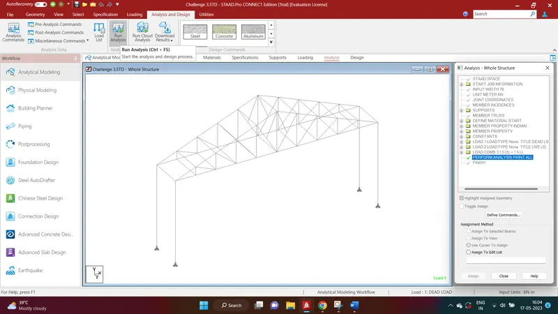
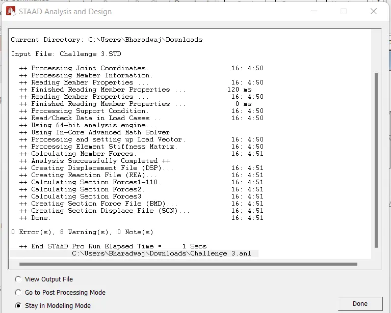
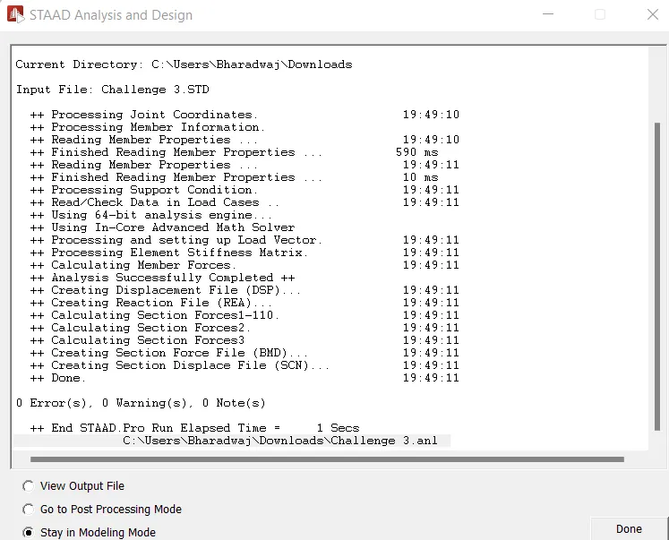
We can notice 0 errors and 8 warnings in the structure
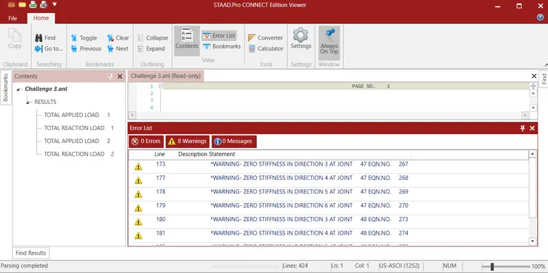
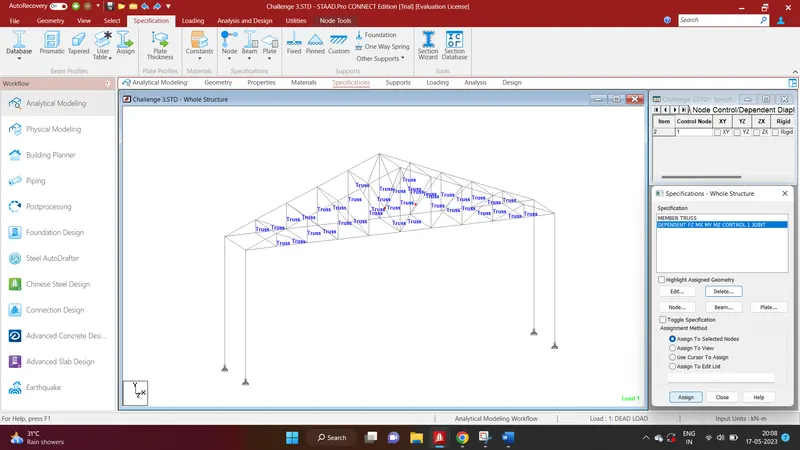
Go to Analytical model to view nodes 47 and 48
Direction 3,4,5,6 means there is no stiffness or reaction against translation in Z axis, rotation in X, Y and Z axis
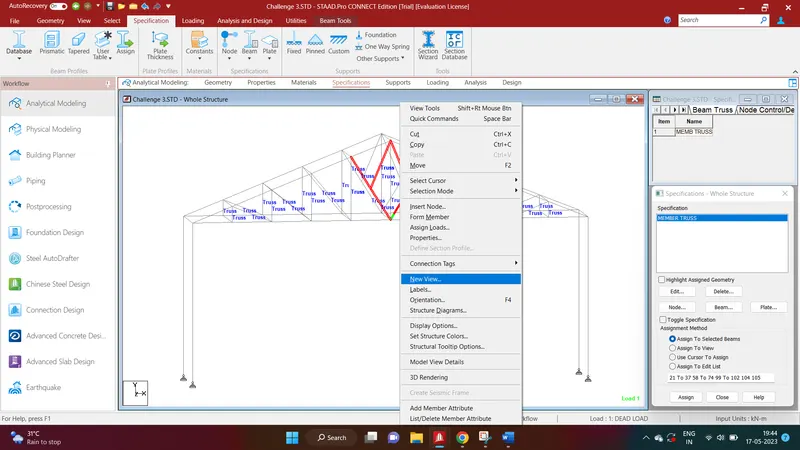
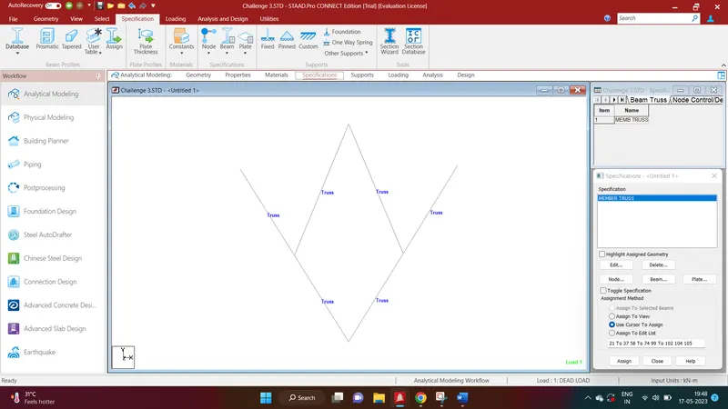
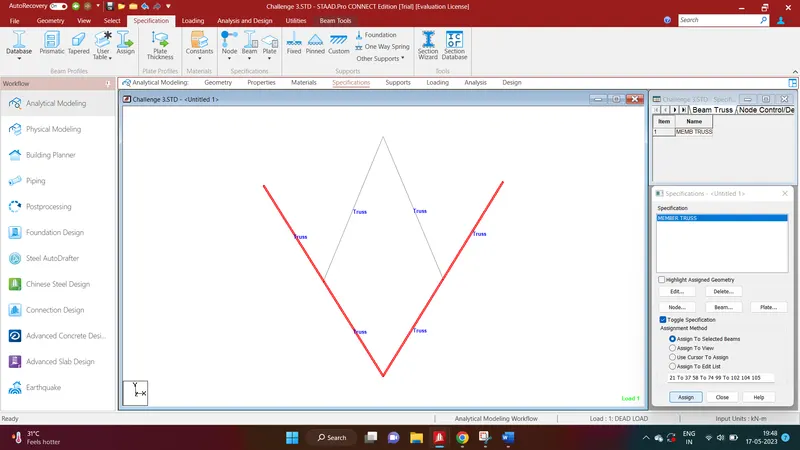
Toggle off the Truss specification to the members supporting the nodes. ie let them be normal beams carrying the moment too
Method 2:
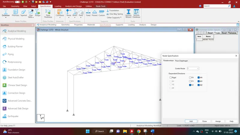
Select the 2 nodes that were in warning condition. Under Node specification, fix the dependant direction as below to introduce stiffness where ever zero stiffness was present
4. AIM:
Design Parameter exercise
In continuation to challenge 1, Apply Design parameter for structure modelled for code IS800:2007.
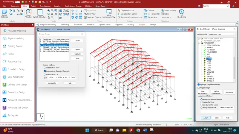
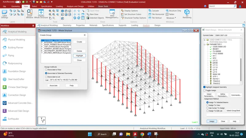
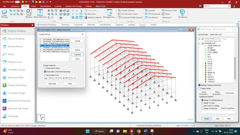
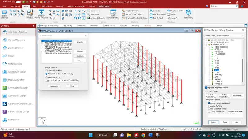
- Effective Length Lx, Ly, Lz for beams, Truss elements
- Effective length factors Ky, Kz for Columns
- Apply other design parameters for respective members
Procedure:
Go to Analysis and Design - Steel
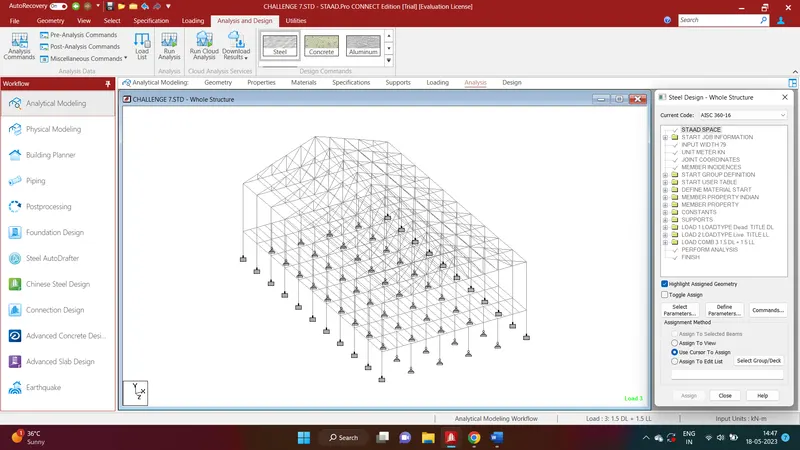
Choose the code as IS 800
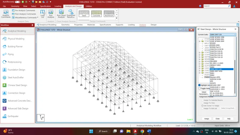
Click on Define parameters
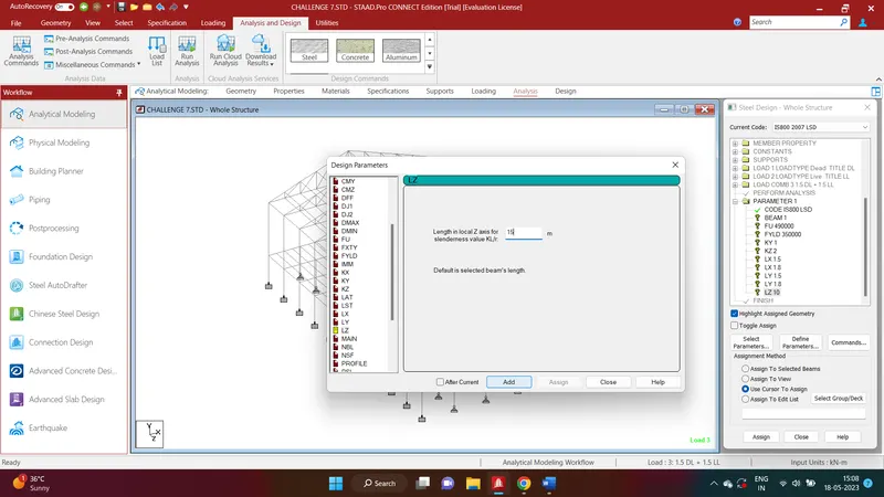
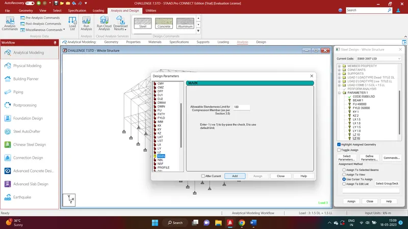
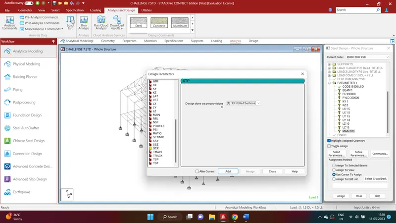
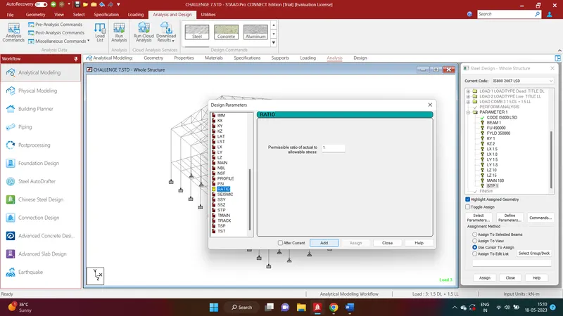
Add the following parameters
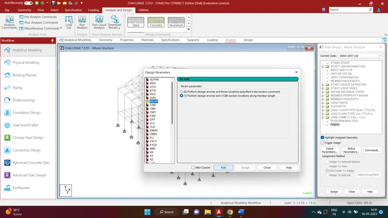
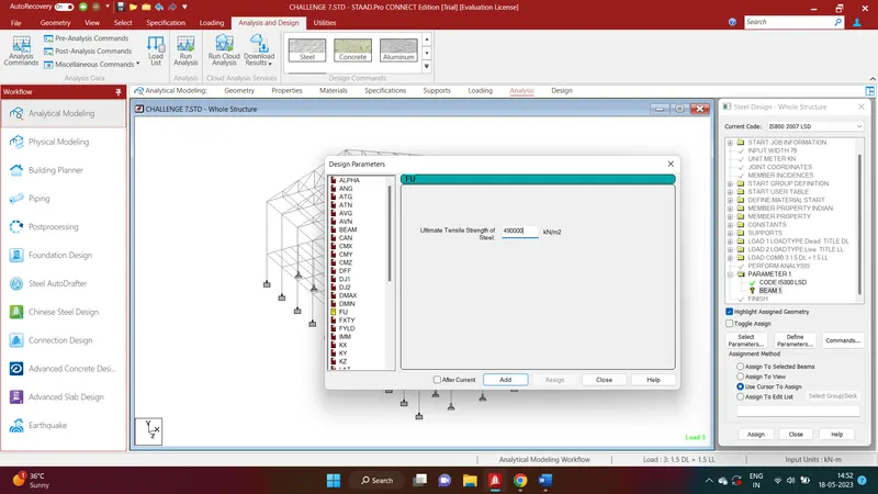
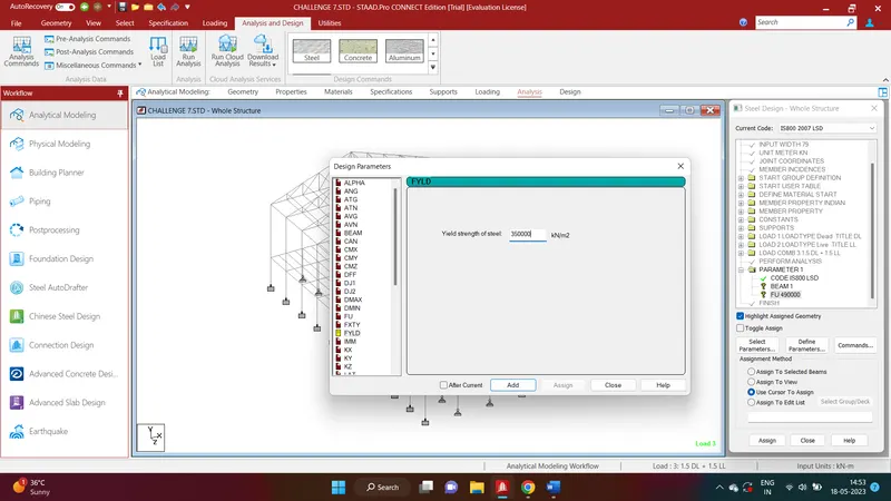
Since we have pinned ends , Ky = 1
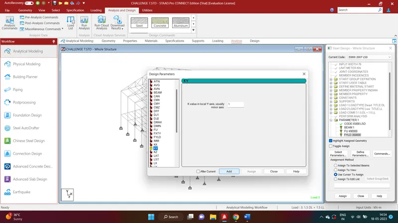
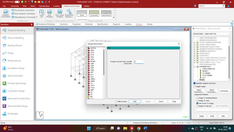
Lx,Ly for rafters = purlin spacing = cos 20 = 3m/hyp = 3.19 (assume as 1.5), for columns (assume girt spacing )= 1.8
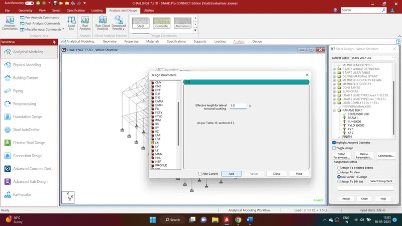
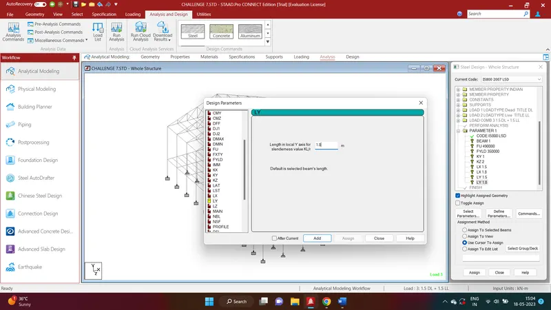
Lz taken as the height of the column = 10m, for rafter = 15m(half the span)
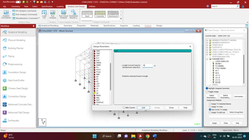
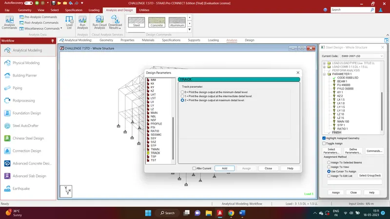
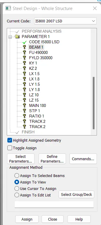
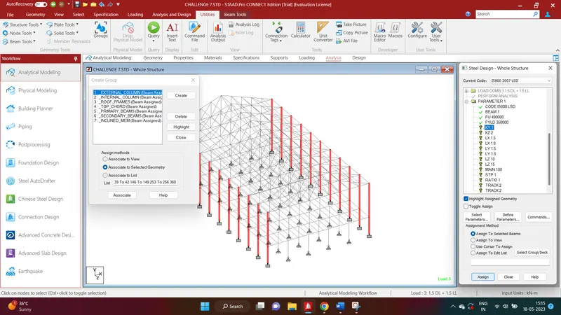
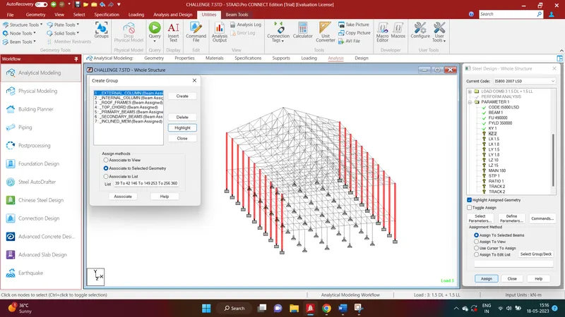
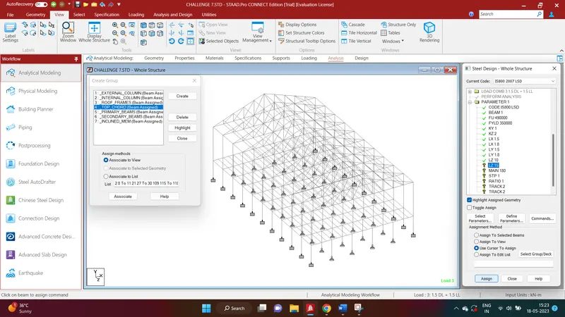
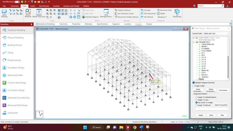
Also include Take off and Check code commands
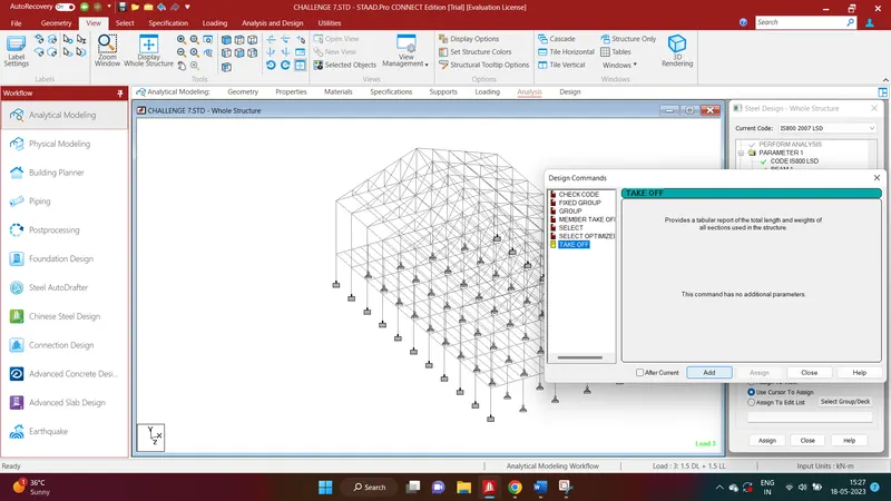
Now run the analysis
Check the utilization ratios. It could be seen that the purlins and rafters have a very high utilization ratio. The member size needs to be altered