To model beams and bracings for industrial steel structures using TSD
CHALLENGE 3
1.AIM:
To create beam properties for First floor and model the beams
Introduction:
The main function of beam is to carry the loads from the slabs or any secondary beam and transfer it to the column. Inorder to create beam properties for first floor, make sure that it matches the ground floor beams and then proceed to the modelling part
In the ground floor level, the secondary beams between grids 1 and 2 are removed to model staircase beams B3
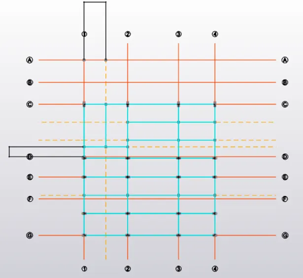
Now we can proceed to the first floor level to model the beams
Procedure:.
- For modelling in first floor level, select the level as FF in the Project workspace
- First floor beams are created using Manage Property Set
- FFB1 – ISMB 350, FFB2 – ISMB 400, FFB3 – ISMB 250 ,Snap – Top, Centre are created
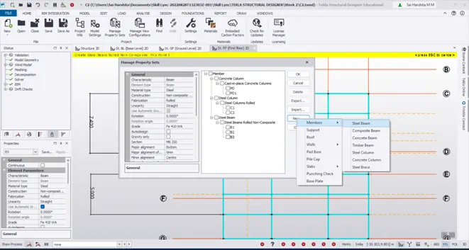
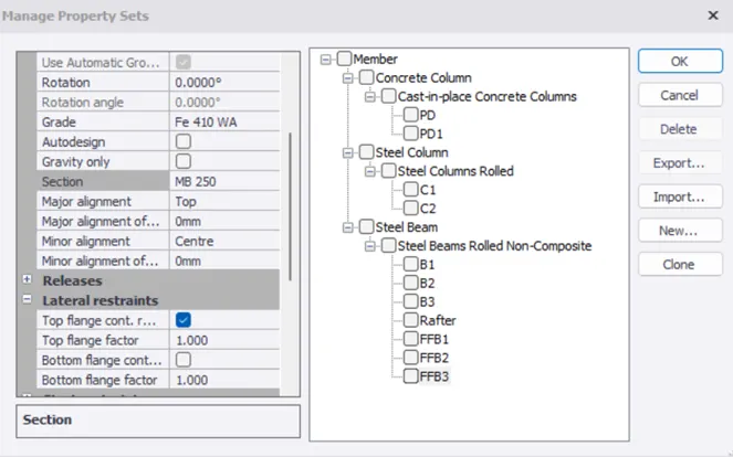
- Carefully check the first floor plan to check for any columns in the place of openings since the plans are different and draw construction lines wherever needed as in the previous floors
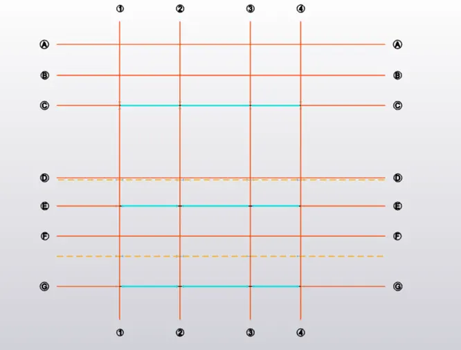
- Also draw construction lines for the secondary beams B3 and for the staircase beams
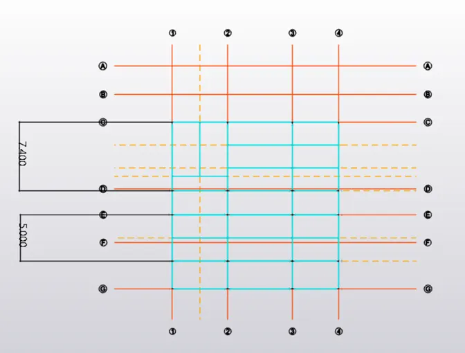
- View the same in 3D
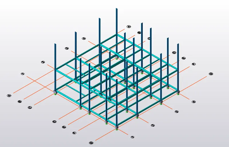
Result:
Thus the first floor beam properties are created and modelled. Construction lines are created wherever necessary to model columns and beams(primary, secondary and staircase beams)
2.AIM:
To create rafter beam on second floor as roof and moment frame action in one direction and add bracings at locations as per the design intent
Introduction:
The following are the functions of rafters, moment frames and bracings in a steel structure
A rafter is a structural component that is used as part of a roof construction. Typically, it runs from the ridge or hip of the roof to the wall plate of the external wall. Rafters are generally laid in series, side by side, providing a base to support roof decks, roof coverings and so on.
Moment frames are specially designed to control lateral or horizontal displacement. They are specially used in earthquake prone areas
On the other hand, bracing is to provide stability and resist lateral loads. Bracing can be used to stabilize the entire steel structure frame and ensure the strength of the steel frame in the length and width directions, bearing wind and horizontal loads on both sides, and transfer these loads to the foundation.
Procedure:
Roof beam level beam modelling:
- Under Levels, click on Roof beam level to view the same
- Draw construction lines wherever required
- Use Manage Property Set to create new property of beam
- RB1 – ISMB 350, RB2 – ISMB 400, RB3 – ISMB 250, Snap – Top, Centre
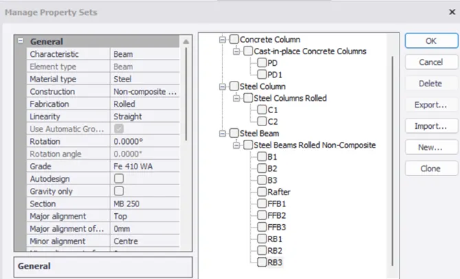
- Model the beams similar to the previous floors
- Primary beam is thus modelled
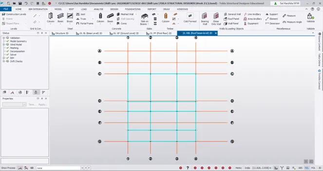
- Draw construction lines and model secondary beams(Staircase beams need not be modelled since it’s a roof beam level)
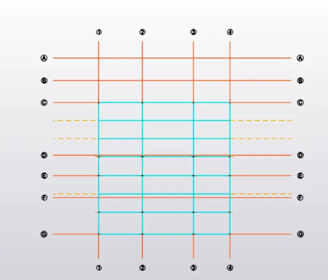
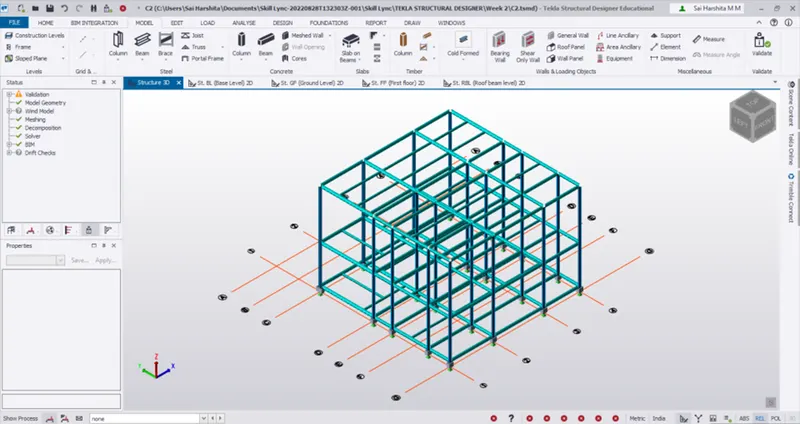
- 3D view as shown below
Frame Modelling:
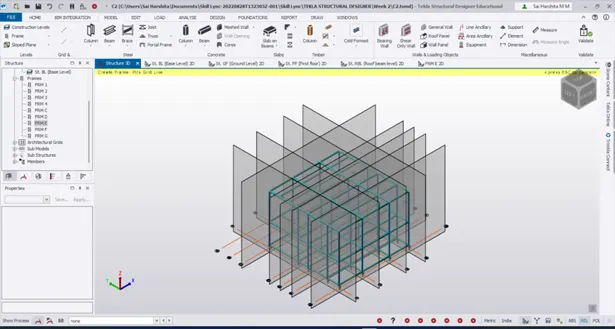
- Now we need to model frames inorder to create rafter
- Click on Model – Frame and select the grids one by one
Rafter Modelling:
- For rafter modelling, click on FRM1 under frames
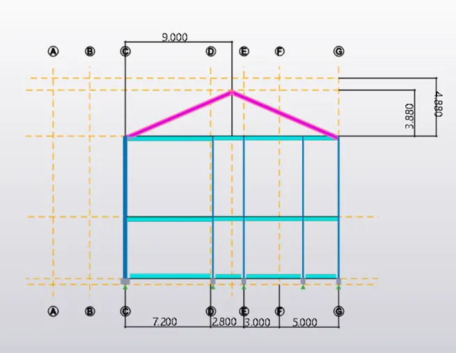
- Draw construction line of 9m from gridline C to identify the midpoint of the sloping roof (7200 + 2800 + 3000 + 5000=9000mm)
- Fix the ridge level at 3.88m from the RBL
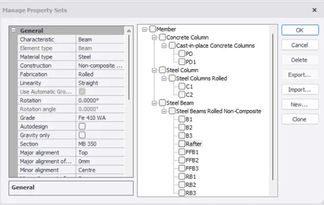
- Go to Manage Property Set and create a Beam called Rafter of ISMB 350
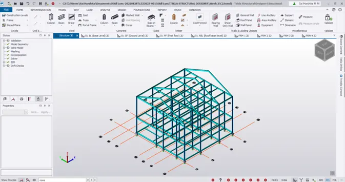
- Select the rafters from the 3D view and go to Edit – Copy
- Pick the reference point and paste it in the respective nodes
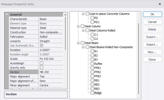
- Create a Ridge beam in Manage Property Set
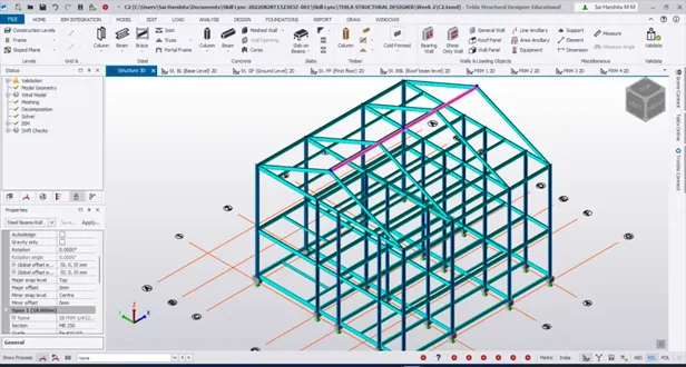
- Validate the model for no errors
Creating Bracings:
- Go to Manage Property Set to create bracings
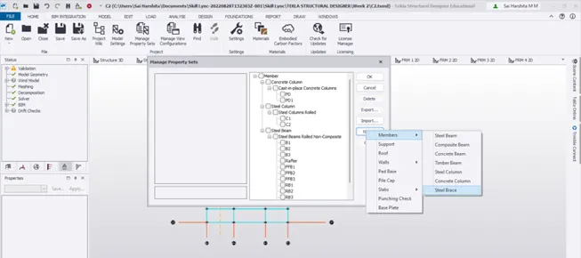
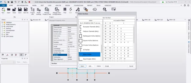
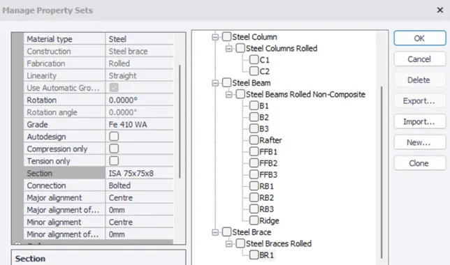
- Go to Model – Brace – X Brace
- Select frame FRM C where we are going to create bracings
- Pick 4 points to create a proper X bracing
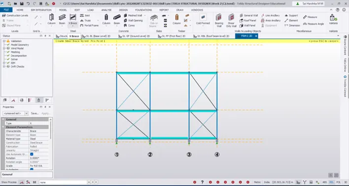
- Similarly select frame FRM G to apply bracing
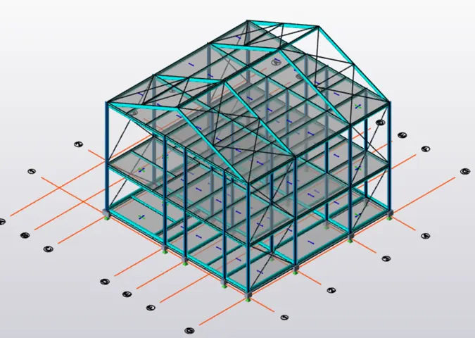
- Go to 3D view to model the roof bracing
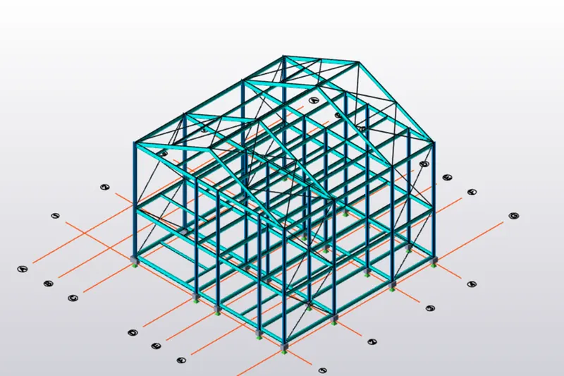
Creating Slabs on the floors:
- To create slabs on the floors, go to Manage property set
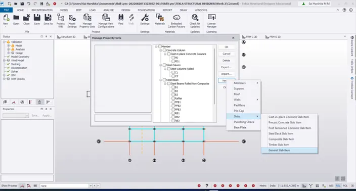
- Create Slab S1(one way) and S2(two way) with the following properties
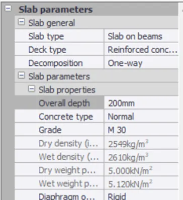
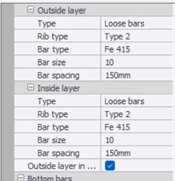
- For S1, change the rotation angle as 90
- Go to Model – Slab on beams
- Choose S1 from the category and just click on the slabs in the GF level to assign the slab property to it
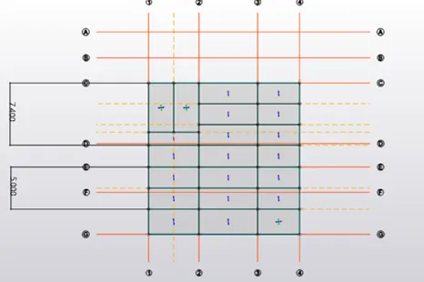
- Find ly/lx ratio and classify the slab as either one way or two way and assign accordingly
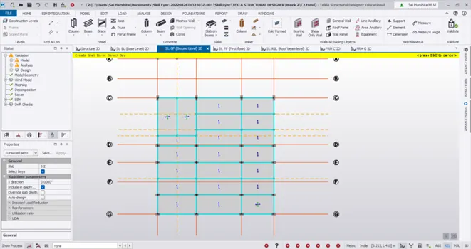
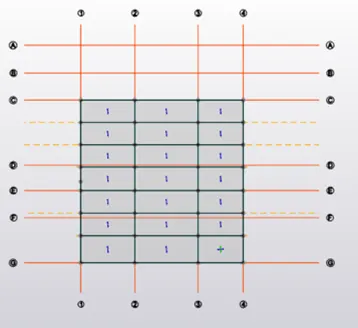
- Repeat the same for FF and RBL too
Creating wall and roof panels:
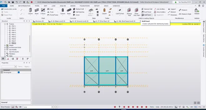
- For creating wall panels, go to Model – Wall panels
- Select the gridline C and start modelling
- Similarly proceed for grid G too
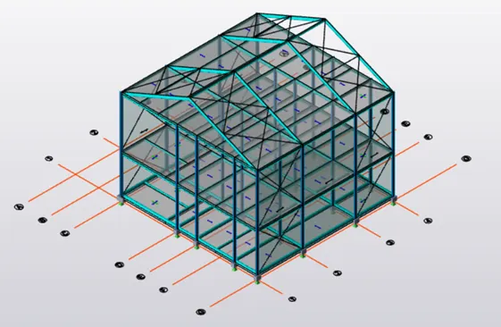
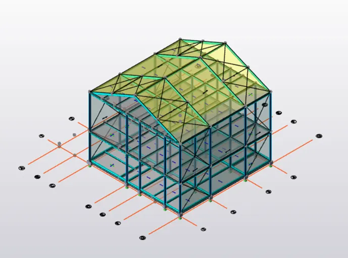
- Model the roof in the similar fashion by clicking on roof panels
Result:
Thus the rafters are modelled , moment frame action and bracings are modelled so as to provide adequate lateral stability. Wall panels and roof panels are created for load transfer and also for providing enclosure