To Analysis and Design of Steel Structures using TSD
CHALLENGE 6
1.AIM:
To Summarize the study for the bending moment, shear force and deflection diagrams for the elements of the model
Introduction:
BMD(Bending moment diagram ) is a diagram representing the variation of bending moment along the length of member .
SFD(shear force diagram ) is diagram representing variation of shear force along the length of structural member .
Deflection also referred to as displacement, which can occur from externally applied loads or from the weight of the body structure itself. Deflection diagrams give the values of deflection at various points in the structure
These diagrams are very much necessary since it helps us understand how much stress a particular member is expected to bear according to which the design of that member could be done
Procedure:
- Before we run the analysis, go to Analyze- Settings
- We have to make sure that the modification factor is equal to 1 for concrete and steel
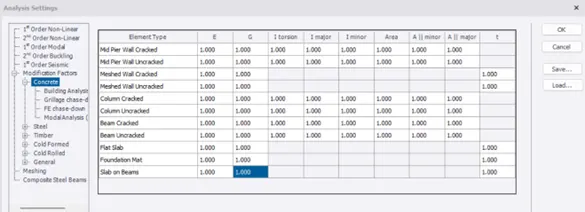
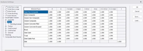
- If any values other than 1 is present, then we need to amend it as 1
- Then we need to generate the load combinations from Load – Load cases
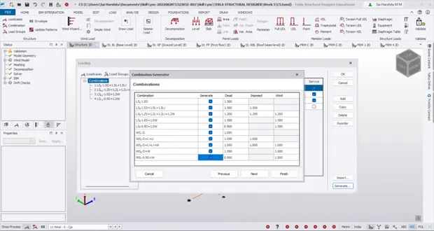
- Tick all the combinations and click Next
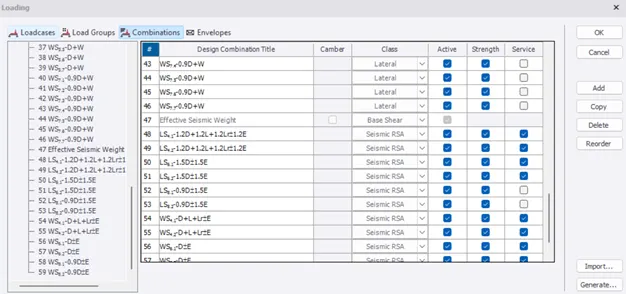
- Now various load combinations are generated
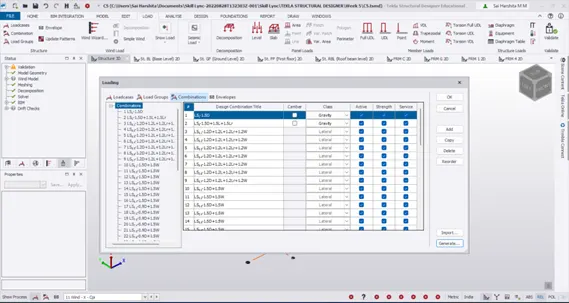
- We notice that the seismic load is yet not created
- So under seismic load, go to Seismic Wizard
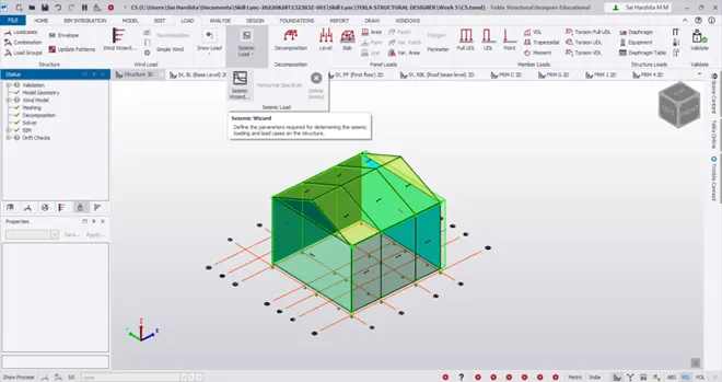
- Analysis procedure – Code Spectra
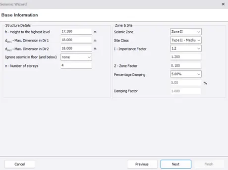
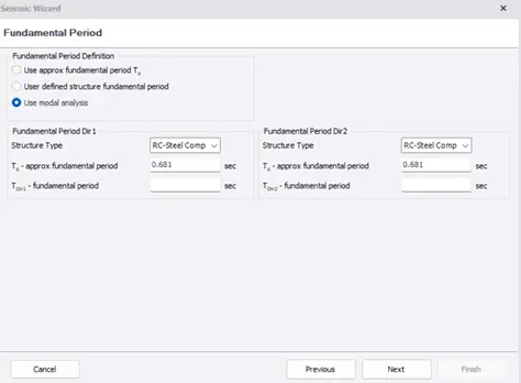
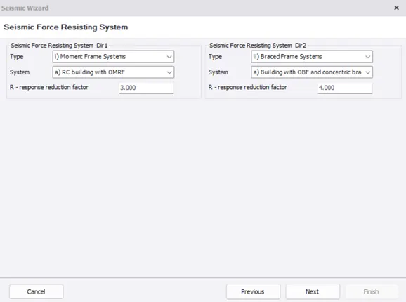
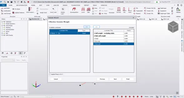
- The combination generator opens
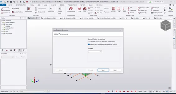
- Click on Next to generate the load combinations
- Validate the model for no errors
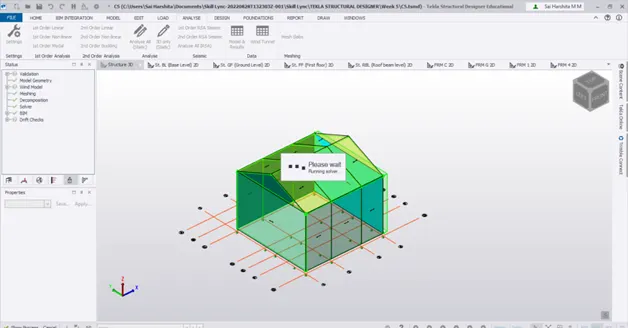
- To start the analysis, go to Analyse- 1st order linear – Select all the combinations
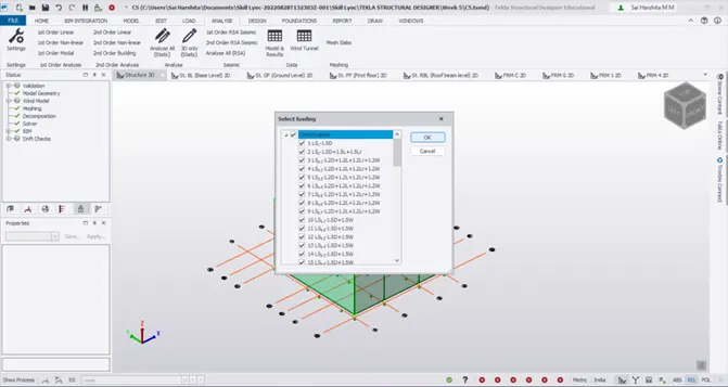
- Now the analysis has begun
a.Deflection diagram:
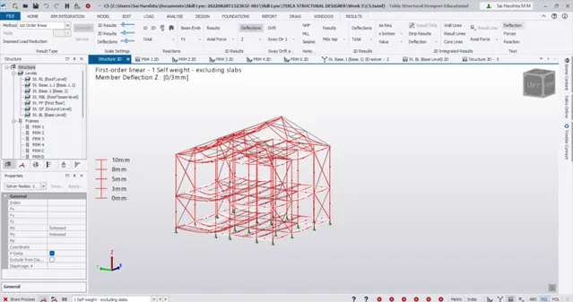
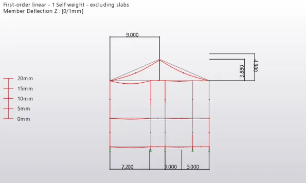
- Under the Results menu – Deflections Z – select any one load combination from bottom and note the deflection values
b.Bending moment diagram:
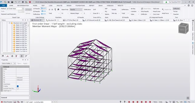
- Similarly check the BMD
- Under Results menu – Results – Moment major
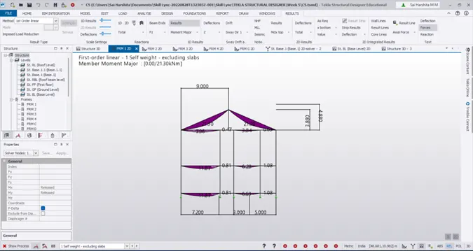
- Observe that all are simply supported beams which have zero bending moments at the supports and maximum at the centre
c.Shear force diagram:
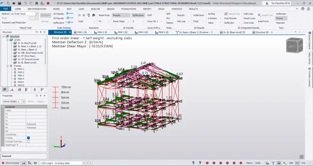
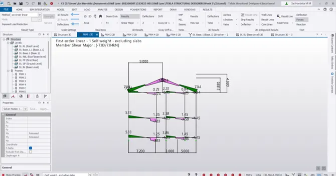
- When we observe the SFD,its seen that the SFDs are for simply supported beams loaded with UDL
- Notice that the shear forces are maximum at the supports and gradually decreases towards centre
- Also notice that the BM is maximum where shear forces are zero
d.Axial force diagram:
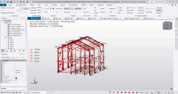
- Under Results- Axial force, check the axial force diagram
- The axial forces are maximum at the GF level
Result:
Thus the deflection, shear force, bending moment and axial force diagrams are studied and interpreted
2.AIM:
To design the members based on the analysis and to outline the thought process in selecting the member sizes along with the foundation design
Introduction:
- First of all the preliminary design has been carried out and analysis is done
- Based on the analysis results of deflection,bending moment,shear force appropriate decisions are taken such as
- increasing the sizing of the members for reducing deflection,
- checking the section modulus and increasing the same for better major moment resistance,
- using UC members for columns for better minor moment resistance and
- ensuring top flange continuously restrained for bucking resistance
Procedure:
- The warnings are shown under the Solver mode under Results tab of the project window
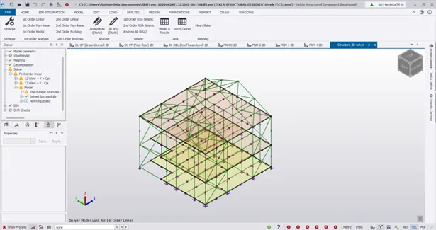
- Under Drift Checks – Overall displacement- Service – Positive – Right click the maximum positive displacement and click Highlight node
- This shows the maximum positive displacement at the node
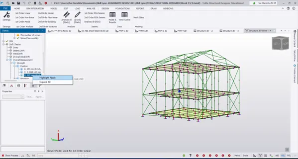
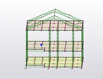
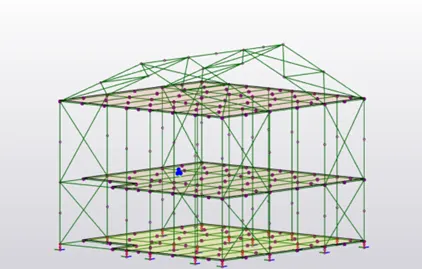
- Its seen that the deflection is maximum in the first floor
- Go to first floor and check the member size
- The member size is ISMB250
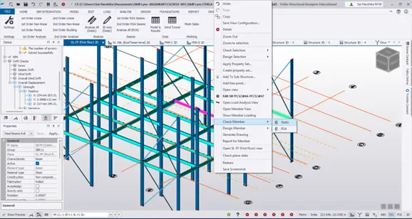
- Go to fist floor 3D view, right click the member and select check member-static
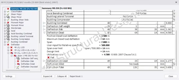
- Under summary, we can notice that it fails also under Deflection dead where the span over limit is Span / 500. So it has to be changed from 500 to 250 as shown
- In the property window,change the deflection limits as 250
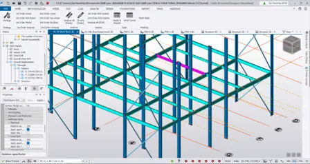
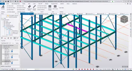
- Also check if the top flange is continuously restrained
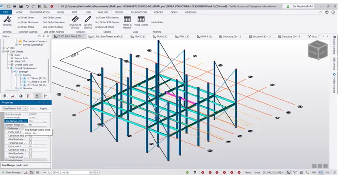
- Now change the member size to MB 550 and run the analysis
- Even if MB 550 is failing, try UK beams and run the program
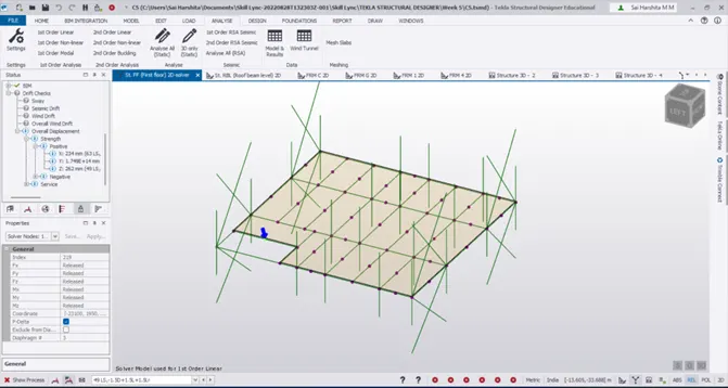
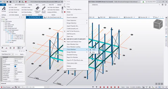
- Seems that the moment major is failing in this member
- Check the elastic section modulus which is 778 cm3
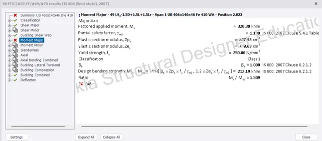
- So choose a member that has the elastic section modulus more than this
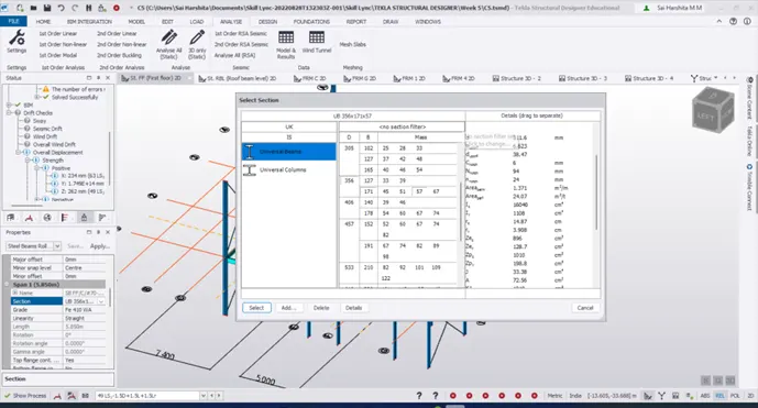
- Here check the elastic section modulus for the chosen member. If its more than the expected elastic section modulus, then we can go for that member
- Now check the member for any failures
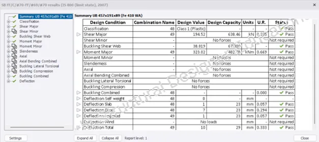
- Once the member satisfies all conditions, run the program again
- Repeat the same procedure for the remaining members also
- Select all the members and select any member size from the property window so that the size is applied
- Check the members
- Now from the scene content, select only steel columns so that the column sizes could be modified
- When any column member is checked, we can notice that almost all of them fails in buckling combined
- So go for UC sections that have wider flanges that provide more modulus so better resistance against minor moment as well
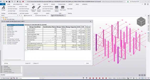
- If the utilization ratio is very small, then decrease the member size by trial and error so that optimum material is used
- Repeat the same for other levels too
- If the member fails in buckling lateral torsion, then check if the top flange continuity restrained is Yes
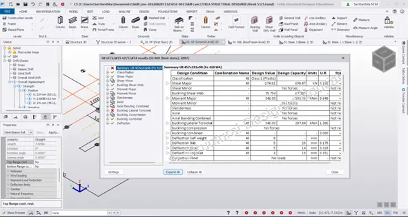
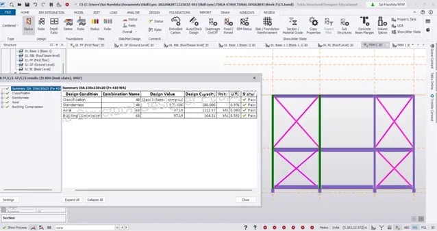
- Now check for bracings
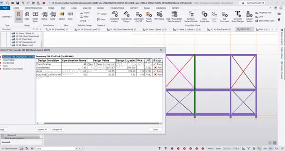
- Choose the optimum angle section for bracing
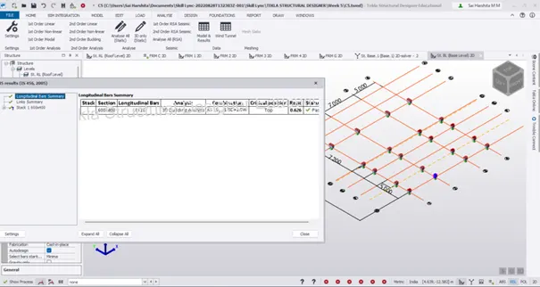
- Go to the Base level and check the pedestal for failures
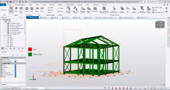
- Go to Structure 3D, window select all the members and check the selection for failures
Pedestal footing design:
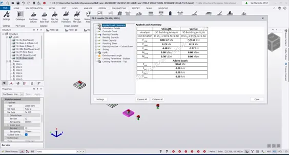
- Select any pedestal , right click to select Open Load Analysis
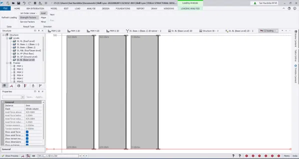
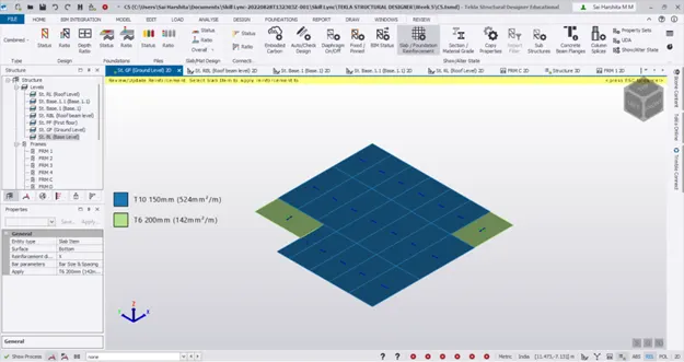
Slab Design:
- Go to Review at the bottom
- In the scene content hide, steel columns,beams,bracing, concrete column
Select slab/ foundation reinforcement
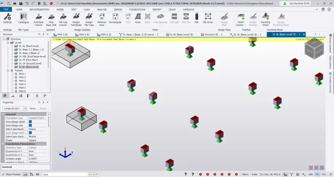
Footing design:
- Go to Base level
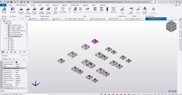
- Under Foundations – Select Pad Base Column
- Click on any support to place the footing
- Select the footing to enter the details of top bars.Just enter type as Loose bars,bar diameter will be automatically designed
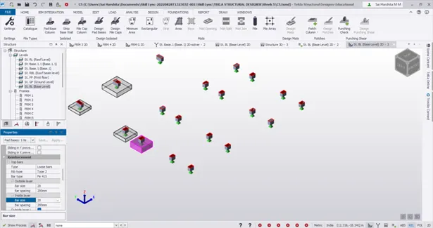
- Right click on the created footing and select Design member
- The footing size and the diameter of the bars used will be designed automatically
Result:
Thus the members are designed according to the design requirements and footing designs are carried out.