Creating 3D Isometric view of various structural elements in AutoCAD
1.AIM:- To create a isometric 3D view of the building with plan and elevation by the use of AutoCAD 2022
INTRODUCTION:- 3D isometric view of building are created by a set of various commands such as extrude,trim etc.3D model canbe visualised from all the three directions i.e. X,Y and Z axis.Real model can be visualised in 3D
3D model can be of three types:-
a) Wireframe model:- It is basically drawn with the lines
b) Surface model:- It is basically created of various lines to join by creating a mesh 0i.e. mesh model
c) Solid models:- It is a model which is having mass
PROCEDURE:-
- Open the AutoCAD 2022 Application software
- Type a command QNEW to save the file
- Type a command units
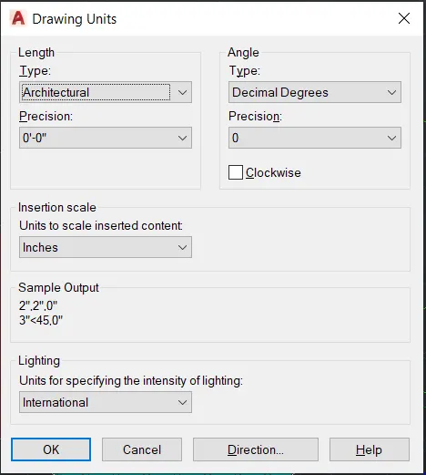
- Go to workspace switching and select 3D model
- Go to top view of the cubic section
- Type a command line
- Specify first point:-0,0
- Specify next point:-@10'9",0
- Specify next point:-@0,10'9"
- Specify next point:-@-10'9",0
- Specify next point:-@0,-10'9"
- Type a command offset
- Specify offset distance:-3'5"
- Specify offset distance:-3'2"
- Specify offset distance:-4'2"
- Specify offset distance:-4'3"
- Specify offset distance:-3'
- Specify offset distance:-3'6"
- Type a command TR. Trimmed the unwanted lines
- Press Escape
- Go to view cube and select left face of the cubic section
- Type a command extrude
- Specify height along Z axis:-4"
- Press Escape
- Type a command UCS
- Specify the first and end point along X axis
- Type a command extrude
- Specify height along Z axis:-9'8"
- Type a command UCS
- Specify the first and end point along Y axis
- Type a command extrude
- Specify height along Z axis:-9'8"
- For window, type a command line
- Specify the point:-@4',0
- Specify next point:-@0,3'2"
- Specify next point:-@-4',0
- Specify next point:-@0,-3'2"
- Press Escape
- Type a command offset
- Specify offset distance:-3" on both the four corners
- Specify offset distance:-4" on both the four corners
- Press Escape
- Type a command TR
- Trimmed the unwanted lines
- Type a command move
- Specify the first base point and the next end point to get the required destination
- Type a command BO
- Pick the internal boundary points to get the required region and then extrude it to a specific height along z axis
- Type a command SUBTRACT to subtract the large area from the smaller area
- Type a command layer
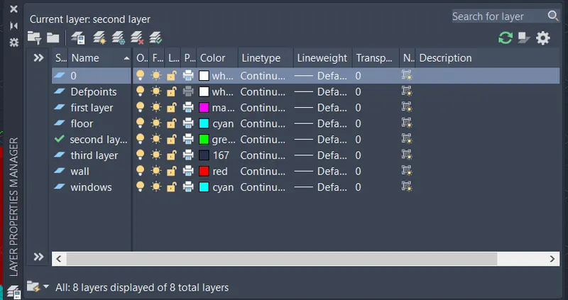
- Type a command BO
- Pick the internal points and then extrude it
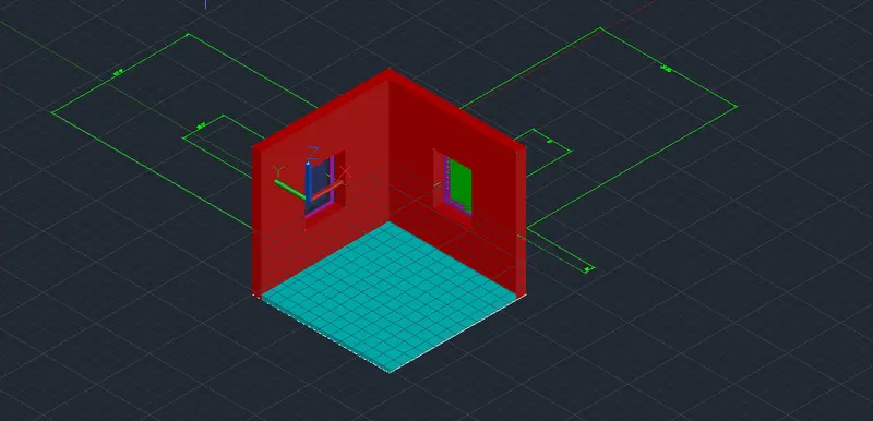
- Type a command VIEW and select the views in different orientations and then save it
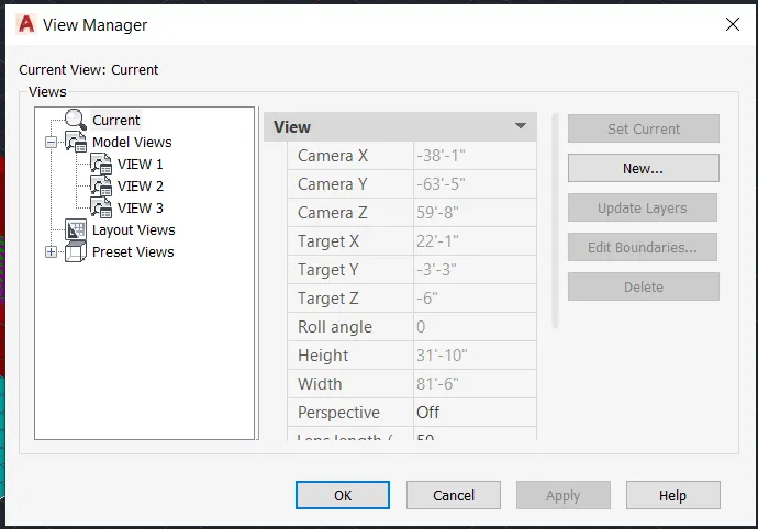
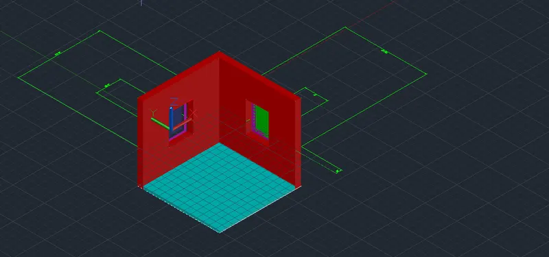
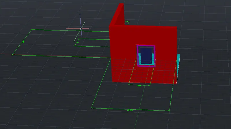
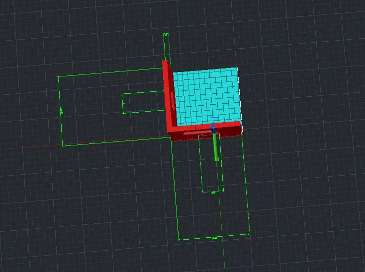
RESULT:- 3D isometric view of the building have been drawn with the use of AutoCAD 2022
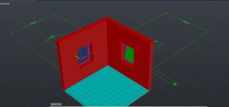
2.AIM:-To create the 3D view of building facade with plan and elevation by the use of AutoCAD 2022
INTRODUCTION:- 3D isometric view of building are created by a set of various commands such as extrude,trim etc.3D model canbe visualised from all the three directions i.e. X,Y and Z axis.Real model can be visualised in 3D
3D model can be of three types:-
a) Wireframe model:- It is basically drawn with the lines
b) Surface model:- It is basically created of various lines to join by creating a mesh 0i.e. mesh model
c) Solid models:- It is a model which is having mass
PROCEDURE:-
- Open the AutoCAD 2022 application software
- Type a command QNEW to save the file
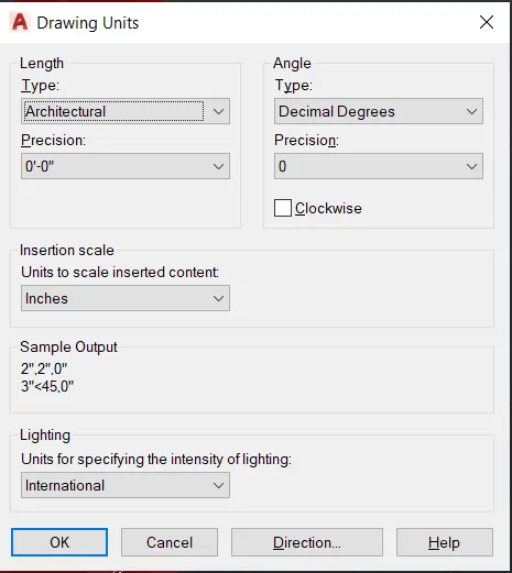
- Type a command units
- Go to workspace switching and select 3D model
- Go to top view of the cubic section
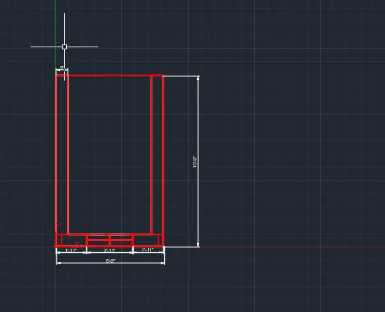
- Type a command line
- Specify first point:-0,0
- Specify next point:-@6'9",0
- Specify next point:-@0,10'9"
- Specify next point:-@-6'9",0
- Specify next point:-@0,-10'9"
- Press Escape
- Type a command offset
- Specify offset diatnce:-1'11"
- Specify offset distance:-3'
- Specify offset distance:-1'11"
- Type a command trim
- Trimmed the unwanted lines
- Go to view cube and select left face of the cubic section
- Type a command EXTRUDE
- Specify height along z axis:-4'6"
- Go to front view of the cubic section
- For windows draw a rectangle of size 3'*4'
- Type a command offset
- Specify offset distance:-2" on both the four corners of the rectangle
- Specify offset distance:-3" on both the four corners of the rectangle
- Draw a mid point line in between the smaller innermost region of the rectangle
- Move to 3D view of the cube
- Type a command 3Drotate and rotate by 90 degree by choosing specific axis location
- Type a command move and select the first base point and end pont to the required destination
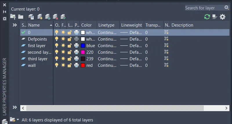
- Type a command LA
- Type a command BO
- Pick the internal boundary points to get the required and then extrude it along Z axis
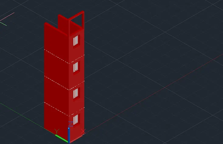
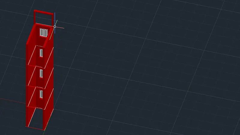
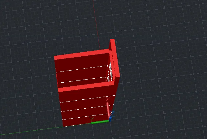
RESULT:- 3D isometric view of the building facade have been drawn with the use of AutoCAD 2022
3. AIM:-To create the 3D isometric view of staircase with handrail with the use of AutoCAD 2022
INTRODUCTION:-3D isometric view of staircase with handrail are created by a set of various commands such as extrude,trim etc.3D model canbe visualised from all the three directions i.e. X,Y and Z axis.Real model can be visualised in 3D
3D model can be of three types:-
a) Wireframe model:- It is basically drawn with the lines
b) Surface model:- It is basically created of various lines to join by creating a mesh 0i.e. mesh model
c) Solid models:- It is a model which is having mass
PROCEDURE:-
- Open the AutoCAD 2022 application software
- Type a command QNEW to save the file
- Type a command units
- Go to front cube of the cubic section
- Type a command line
- Specify first point:-0,0,0
- Draw a riser of specific height 6" and thread 1'
- Copy the steps 0f 9 times and move it to a required location
- Move to 3d view of the cube
- Type a command BO
- Pick the internal boundary points to get the required region
- Type a command layer
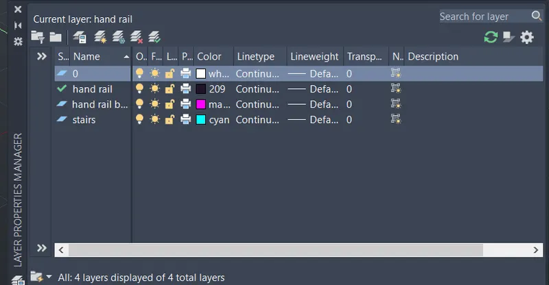
- Type a command extrude
- Specify height along z axis:-3'
- Type a command circle 2" for hand rail
- Type a command extrude and specify haight along z axis:-3'2"
- Type a command 3DPOLY
- Draw a line along center point
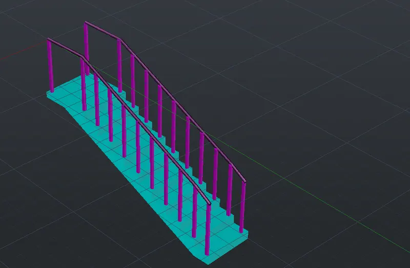
RESULT:-3D isometric view of staircase with handrail have been drawn with the use of AutoCAD 2022
4. AIM:- To create the spread wall with footing along with the craetion of door with the use of AutoCAD 2022
INTRODUCTION:-3D isometric view of spread wall with footing are created by a set of various commands such as extrude,trim etc.3D model canbe visualised from all the three directions i.e. X,Y and Z axis.Real model can be visualised in 3D
3D model can be of three types:-
a) Wireframe model:- It is basically drawn with the lines
b) Surface model:- It is basically created of various lines to join by creating a mesh 0i.e. mesh model
c) Solid models:- It is a model which is having mass
PROCEDURE:-
- Open the AutoCAD 2022 Application software
- Type a command QNEW to save the file
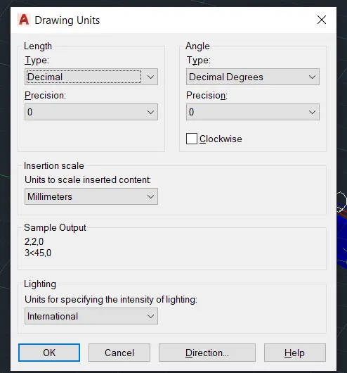
- Type a command units
- Go to top view of the cube section
- Type a command line
- Specify first point:-@230,0
- Specify next point:-@0,7500
- Specify next point:-@-230,0
- Specify next point:-@0,-7500
- Press Escape
- Type a command offset
- Specify offset distance:-50 from both the sides
- Type a command extend to extend the line
- Press Escape
- Type a command offset
- Specify offset distance:- 115 from both the sides
- For spread footing select the right cube of the cubic section
- Spread footing have been drawn with the use of specific commands such as line,trim etc
- Type a command BO
- Pick the internal boundary points to get the required region
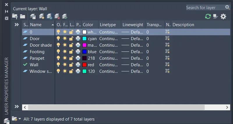
- Type a command LA
- Type a command extrude and specify the height along z axis:-7500
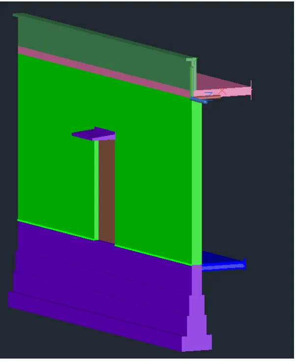
RESULT:-Spread footing with footing along with the creation of door have been drawn with the use of AutoCAD 2022