Project 2_Creating a 3D rendered model for a Residential Building in AutoCad
1.AIM;-TO create a 3D rendered model for a residential building with the use of AutoCAD 2022
INTRODUCTION:- 3D models are of following three types:-
a) Wireframe model:- It is basically drawn with the lines.
b) Surface model:- It is basically created of various lines to join
c) Solid models:-It is a model which is having mass
Rendering is a process in which gives realistic process of the products. It starts with the 3D modelling.
The followning dimensions have been provided for residential building which is given below:-
a) Kitchen Room ( 1.96 m* 2.43 m)
b) Bedroom ( 2.43 m*2.48 m)
c) Dining room (2.89 m*3.41 m)
d) Toilet 2 Nos ( 1.38 m*1.09 m)
e) Dining Room (2.89 m*3.41 m)
f) Living Room ( 1.96 m*2.58 m)
g)Bedroom (2.43 m* 2.58 m)
PROCEDURE:-
- Open the AutoCAD 2022 Application Software
- Type a command QNEW to save the application file
- Type a command UNITS
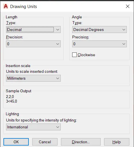
- Select 3D modelling switch options
- Select top view of the cubic section
- Draw the plan of building as per specifications provided in the given drawing
- Select the 3D view cube space
- Type a command LA
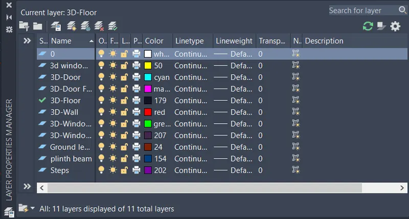
- Type a command BO
- Pick internal points
- Select the region and press Enter
- Type a command extrude. Specify the object
- Select extrude of specific height along z axis:- 3000
- For wall type a boundary of wall of specific height 1000
- For ventilation type a boundary wall of specific height 600
- For plinth beam extrude the bottom layer to a specific height -600
- For ground floor extrude the bottom layer to a specific height 100
- Select the boundary layer and give it specific region
- For parapet wall extrude the top most layer to a height of 600
- For top floor extrude it a height of 150
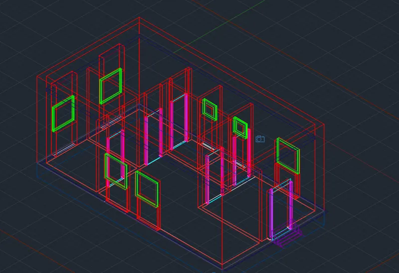
- For steps extrude it to a specific height of 150 mm for 1000 mm length
- Type a UCS command and then select the axis for extruding the object along specific plane
- Draw a door in 3D by typing a command EXTRUDE to a particular height 2000
- For window type a command BO
- Pick an internal point
- Select the particular region for window frame
- Type a command SUBTRACT to subtract the bigger object from the smaller one
- For window mullion type a command BO
- Pick an internal point and then select the particular region
- Type a command Subtract select the bigger region and then subtract the bigger region from the smaller one
- Foe window glass define the layer by a specific colour. Type a command BO
- Pick an internal point and then select the particular region
- Type a command Subtract to subtract the bigger object from the smaller one
- Selct the window frame and then extrude it to a particular height 75 mm
- Select the window glass and then extrude it to a particular height say 12 mm
- Select the mullion and then move it to a specific distance say 12 to 15 mm
- Slect the window object and move it to a specific destination
- For creating a doors type a command BO
- Pick an internal point and then allowed it to a particular object say 75 mm for door frame and then again extrude the object to 25 mm
- For camera view create a cylinder and then extrude it for 1500 mm
- Specify the camera location and named the camera say cam1
- Specify the camera height 1500
- Specify lens length 30 mm
- Saved it in view manager cam1
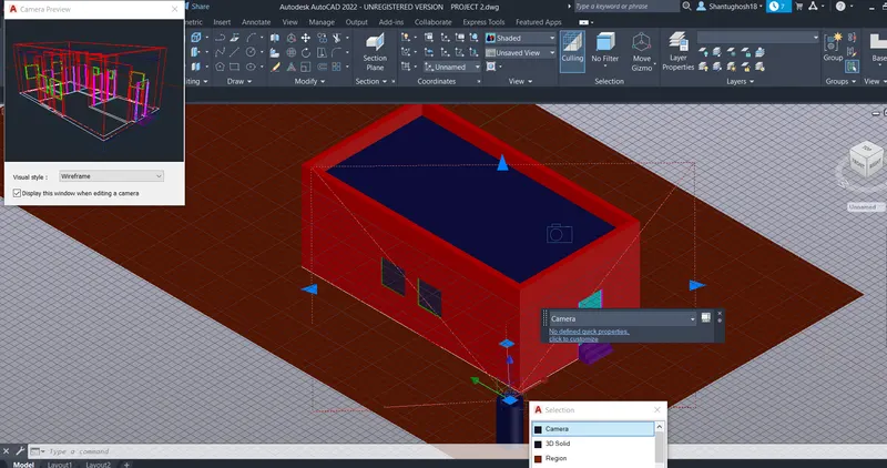
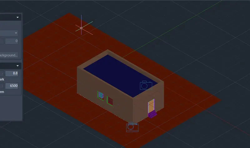
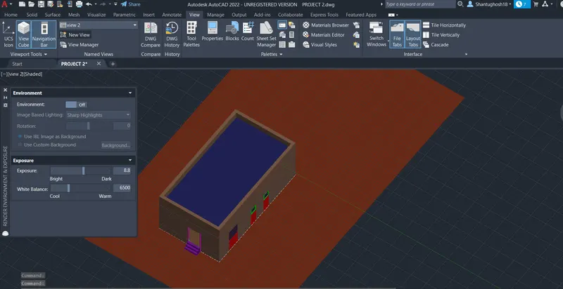
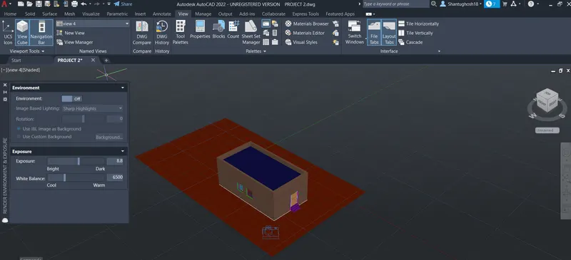
- Set the light. The visualise>Create light>Distant Light. Allow the distant light to set
- For material browser type a command RMAT and select it as per user preferences
- For selecting an object type a command SETUV mapped the object and then assign the material by using material browser collection
- Go for visualise> Render>Render Environment and Exposure>Render On>Select image based lightning
- Again go to rendering option>select the size . Type RR for rendering
- Save the render as jpg or png file
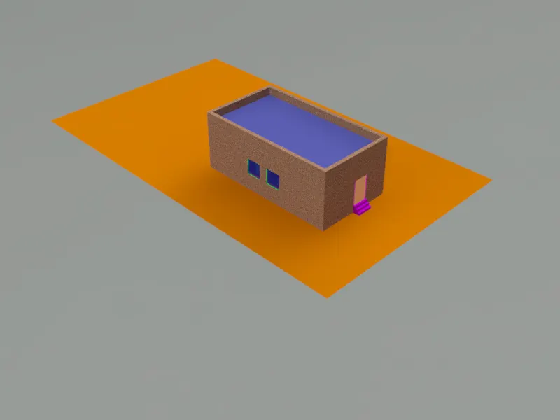
RESULT:- 3D model of residential building have been drawn along with rendering with the use of AutoCAD 2022