Structural Modelling using Etabs 2018
`
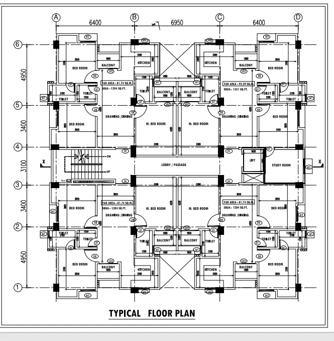
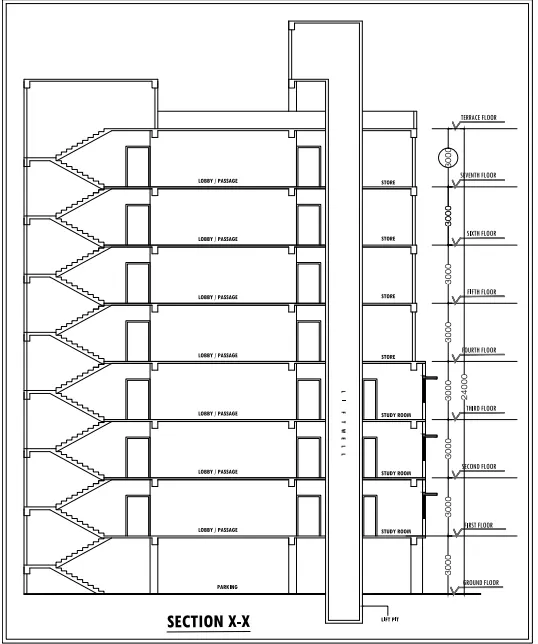
1. The architectural drawings for a G+7 residential building in zone 5 has been provided. The floor plan is the same for all 7 floor levels. Possible column positions have also been provided. Conceptualize a framing plan layout and then model the building in Etabs. The following architectural drawings have been provided:
- Typical floor plan – The location and thickness of the brick walls and the use of the
space (for estimating live load) can be obtained from this plan - A building section through the staircase and lift core is provided
- Parking layout in the ground floor – the column/shear wall arrangement must not
obstruct entry/exit of vehicles.
The following loadings are to be taken into account: - Brickwall made of AAC blocks
- Finishes – floor tiles of 75 mm thickness
- Live loads as per IS 875 part 2
- Water tank of 20 KL above the staircase at Mumty level
- Lift Machine room at mumty level above lift core
The structural model must comply with provisions of IS 1893 and IS 13920.
Run a modal response spectrum analysis and check analysis results of the etabs model for inter-storey drift requirements, vertical & planar irregularities, minimum shear wall requirements,maximum axial load ratio for column and shear walls, effective moment of inertia for beams and columns etc
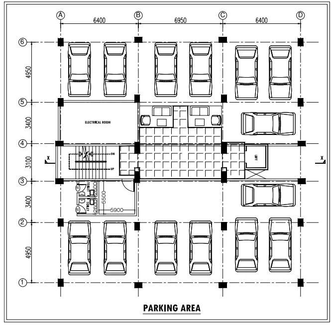
AIM:- To model and analyse the architectural plan for a G+7 residential building in zone 5. To run a model response spectrum analysis and to check the analysis results of the etabs model for inter-storey drift requirements, vertical and planar requirements, minimum shear wall requirements etc.
INTRODUCTION:- All the steps are going to be mentioned along with step by step procedure.
PROCEDURE:-
- Open ETABS 2020 software.
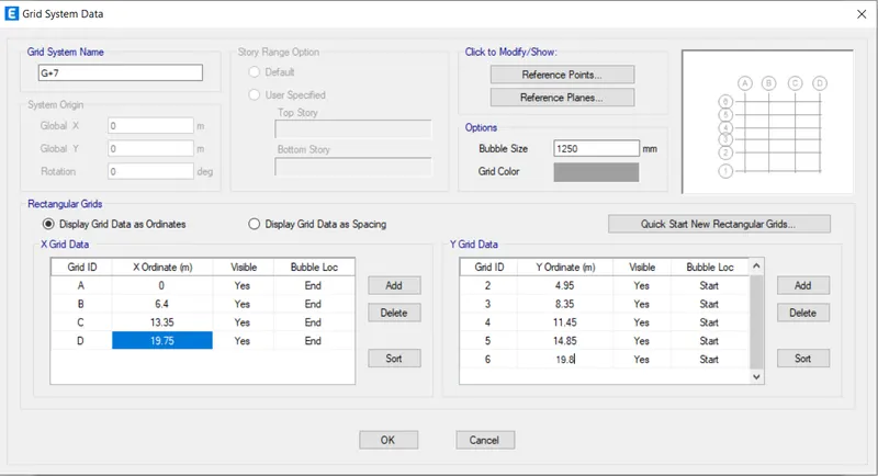
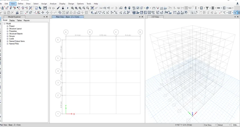
- Create a new model for specifying grid data along x and y axis direction.
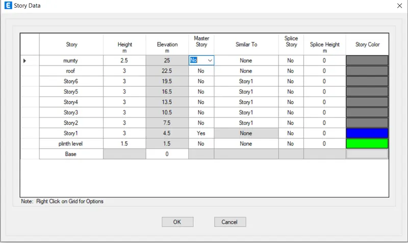
- Create a story date as per elevation drawing
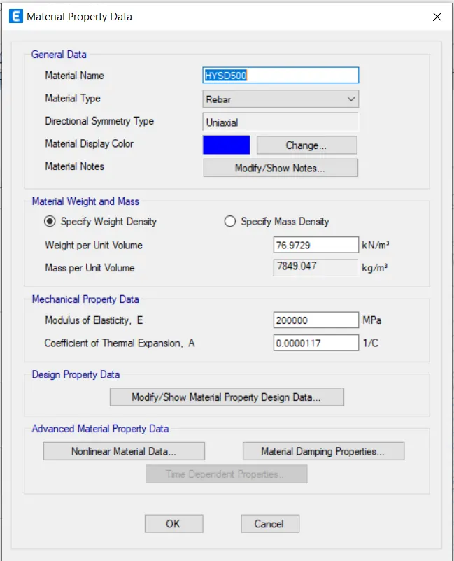
- Define material property for rebar and concrete
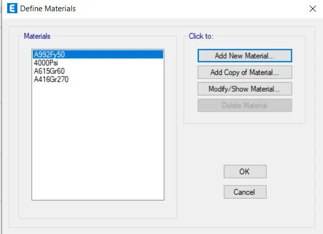
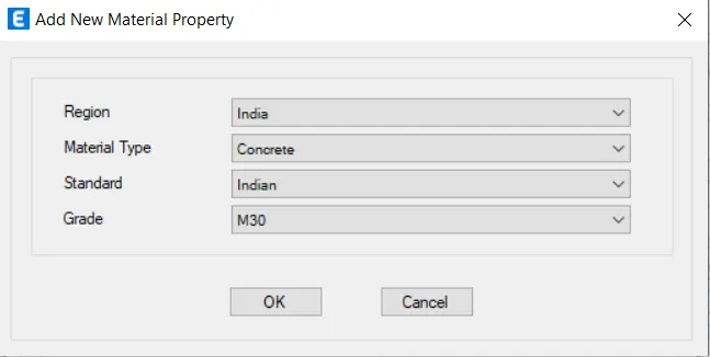
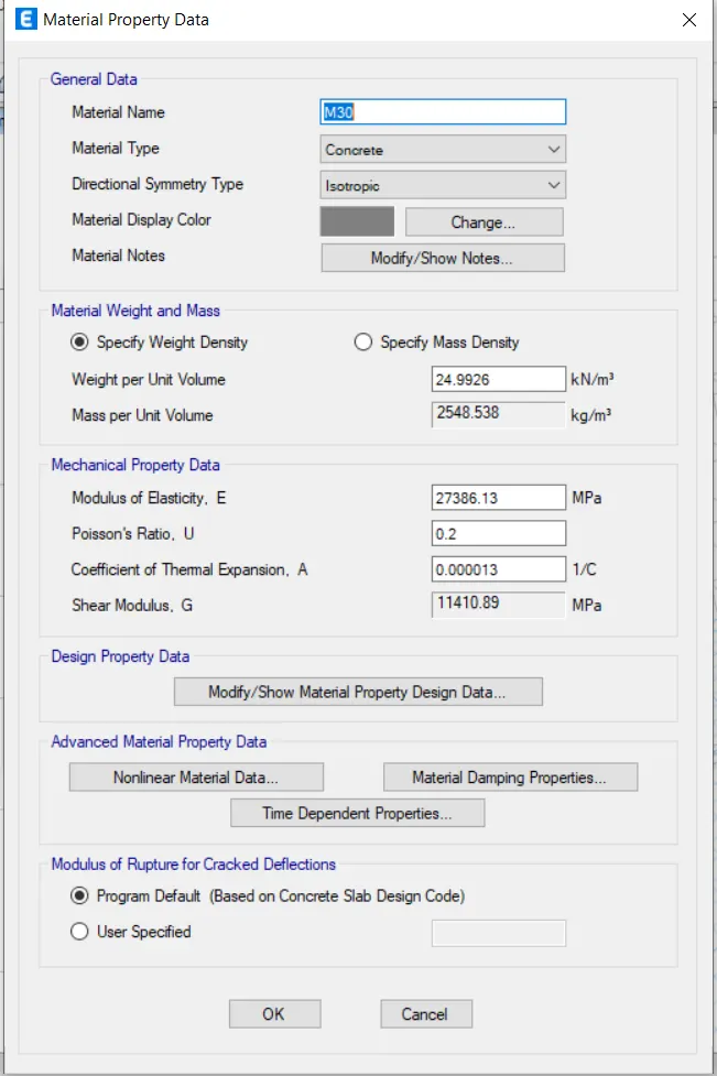
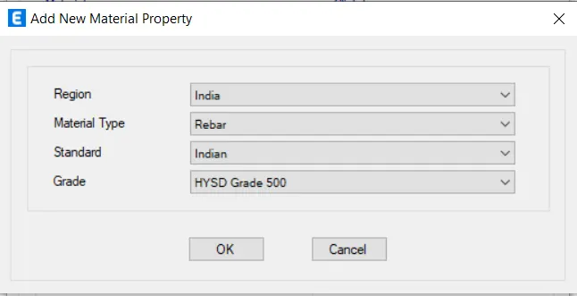
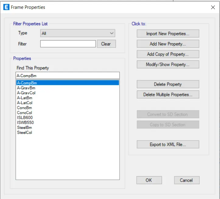
- Select frame properties for column and beam
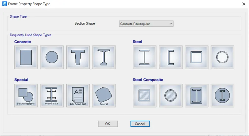
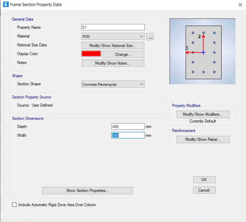
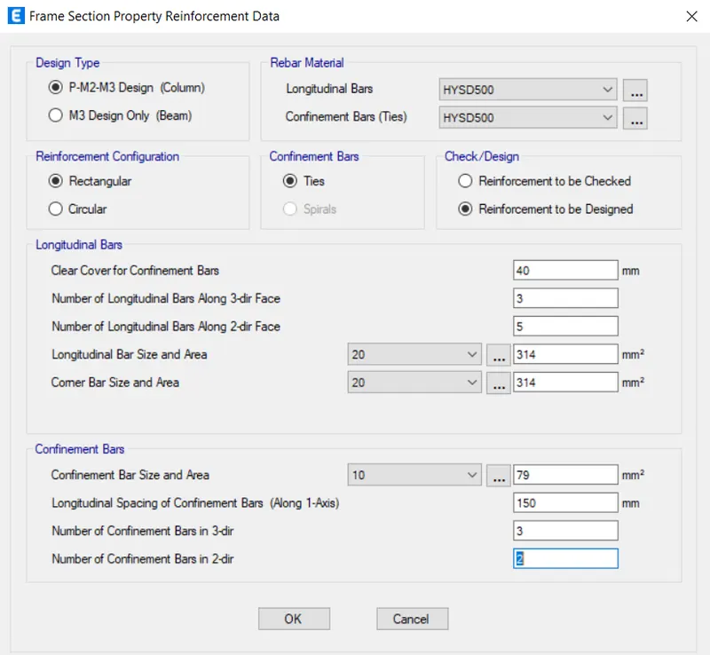
- Specify the depth and width of the column C1 as 450 mm and 300 mm
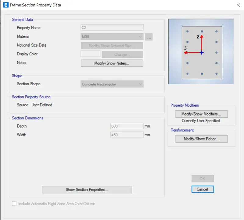
- Specify the depth and width of the column C2 as 600 mm and 450 mm
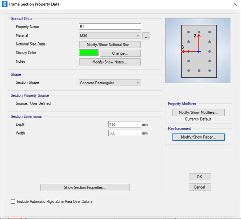
- Specify the depth and width of the beam as 450 mm and 300 mm
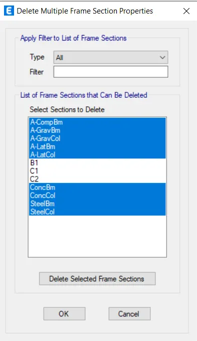
- Selected delete multiple frame properties.
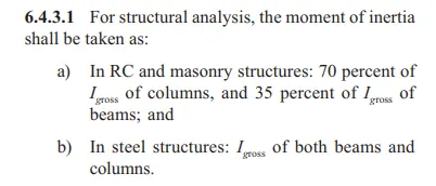
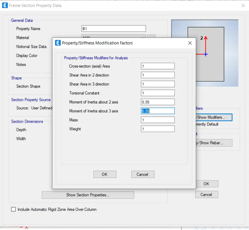
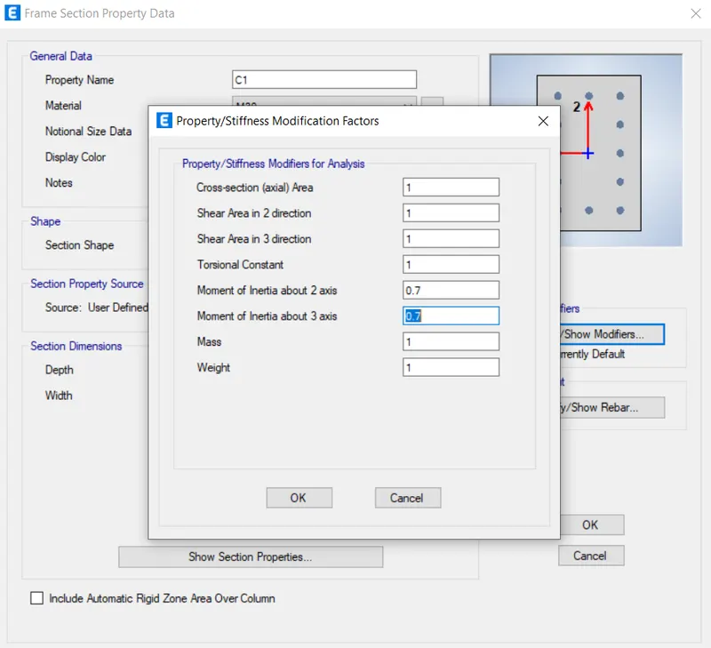
- As per IS 13920 - 2016, the moment of inertia shall be taken as 70per cent of gross moment of inertia for column and shall be taken as 35 percent of gross moment of inertia for beam (Clause 6.4.3.1)
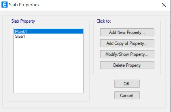
- Select slab properties
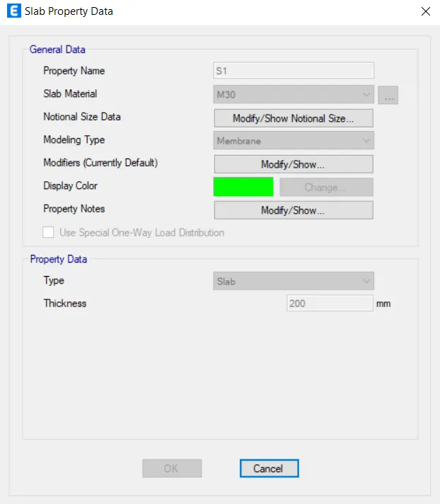
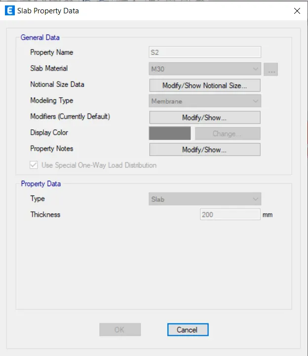
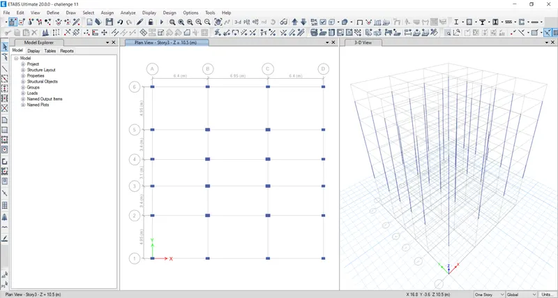
- Draw the columns as per specified grid
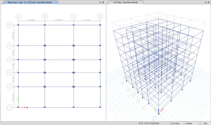
- Draw the beams as per specified grid
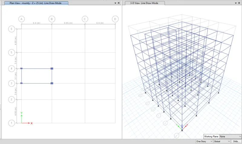
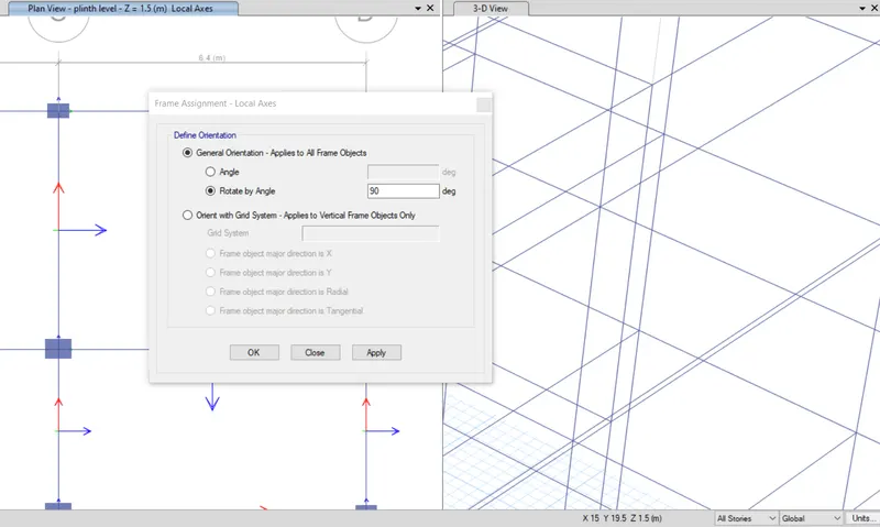
- Orient the column by 90 degree
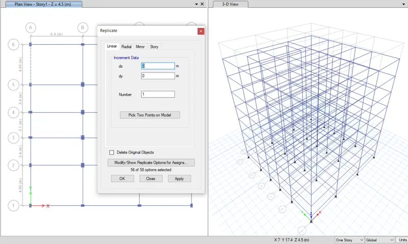
- Replicate the wall arrangements as per architectural drawings
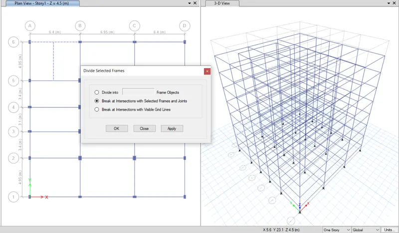
- Divide the selected frames at intersection point
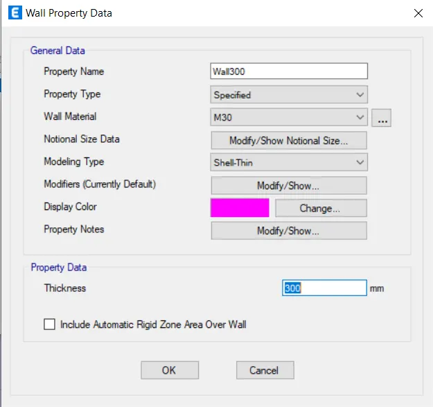
- Define shear wall property
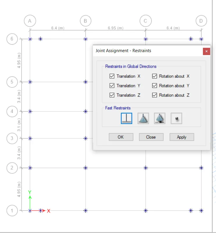
- Define joint assignments as fixed one
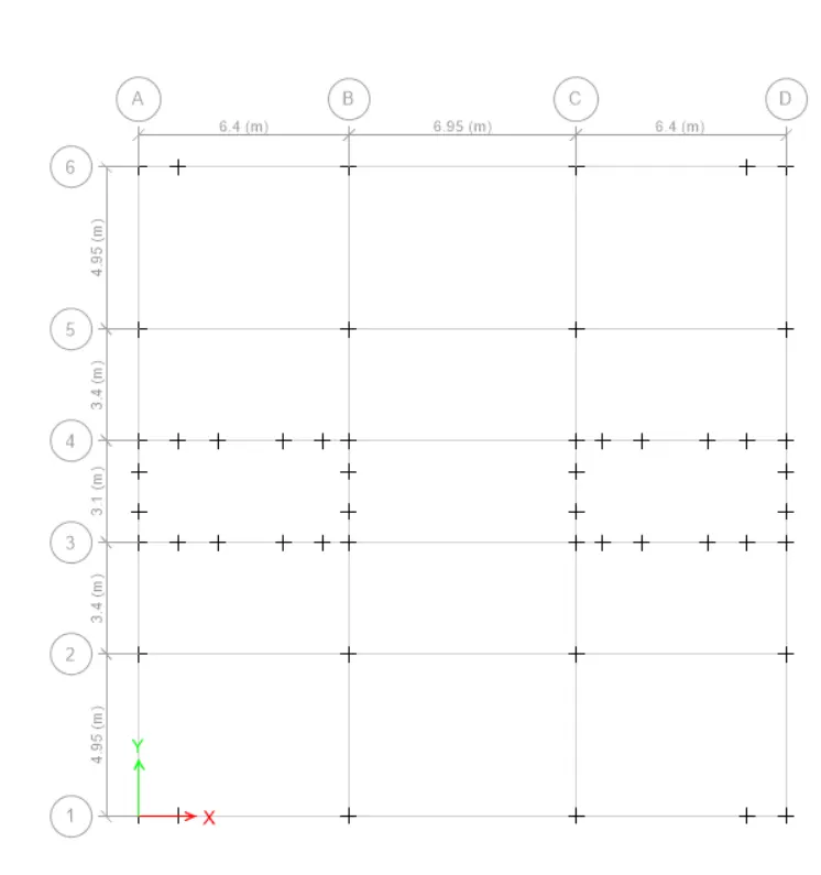
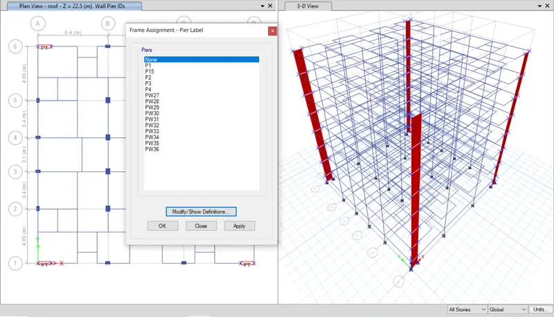
- Assign pier label for shear wall as frame assignment
- Assign slab for similar stories
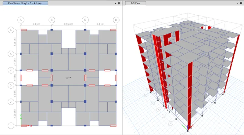
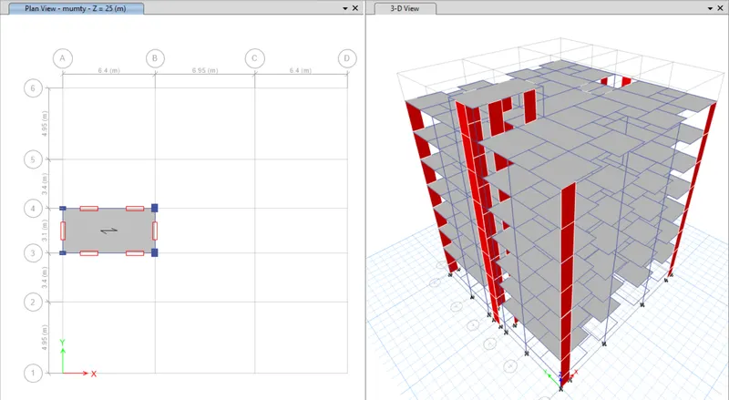
- Define load patterns
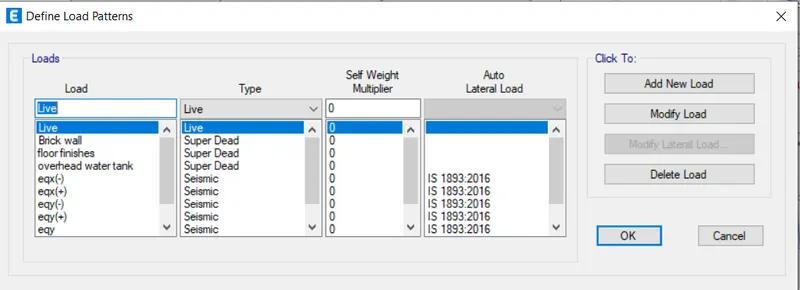
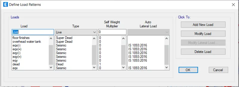 a
a
a) Dead load and live load Calculations:-
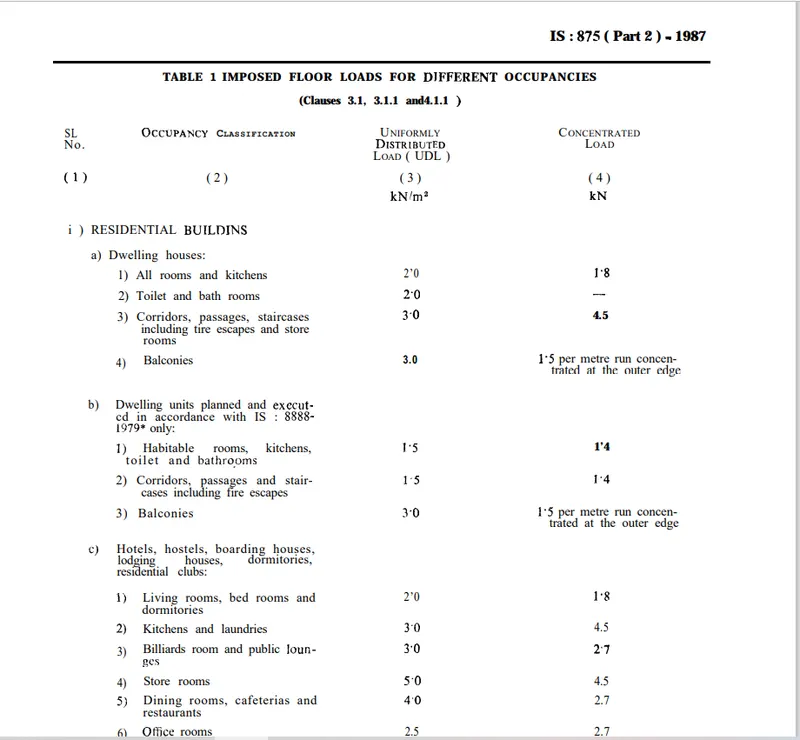
1. Live loads imposed for different occupancies as per clause 3.1, 3.3.1 and 4.1.1 IS 875 (Part 2) - 1987
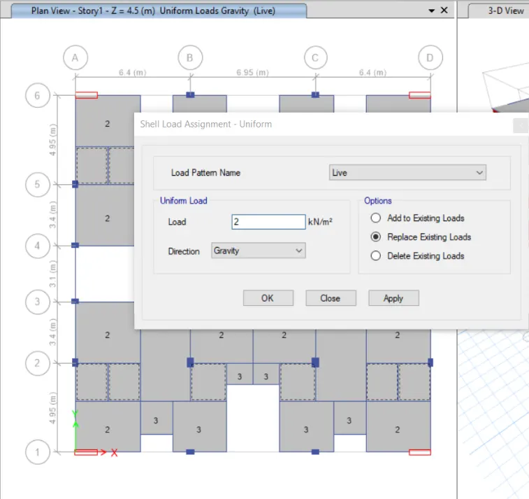
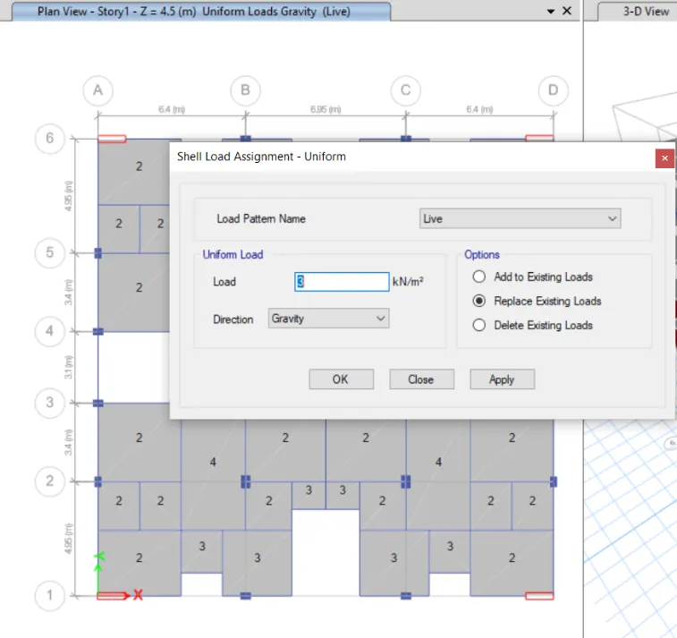
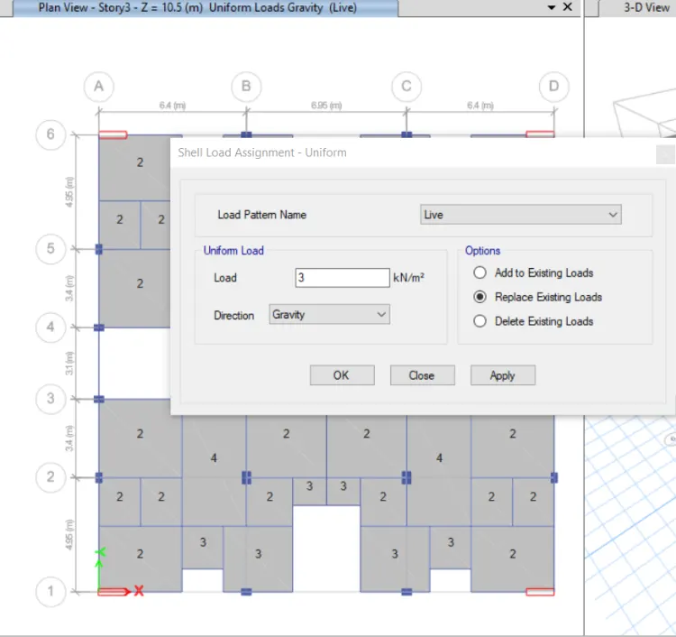
2. Live load for slabs as per architectural drawing:-
Bedrooms:- 2 KN/m^2
Balcony:- 3 KN/m^2
Kitchen:- 3 KN/m^2
Toilet:- 2 KN/m^2
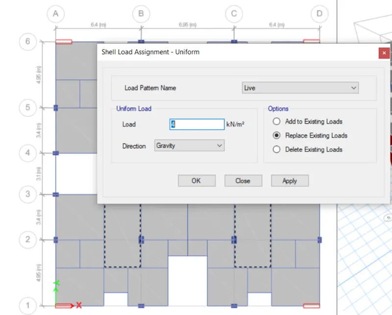
Drawing Room:- 4 KN/m^2
Corridor, passage, staircase:- 3 KN/m^2
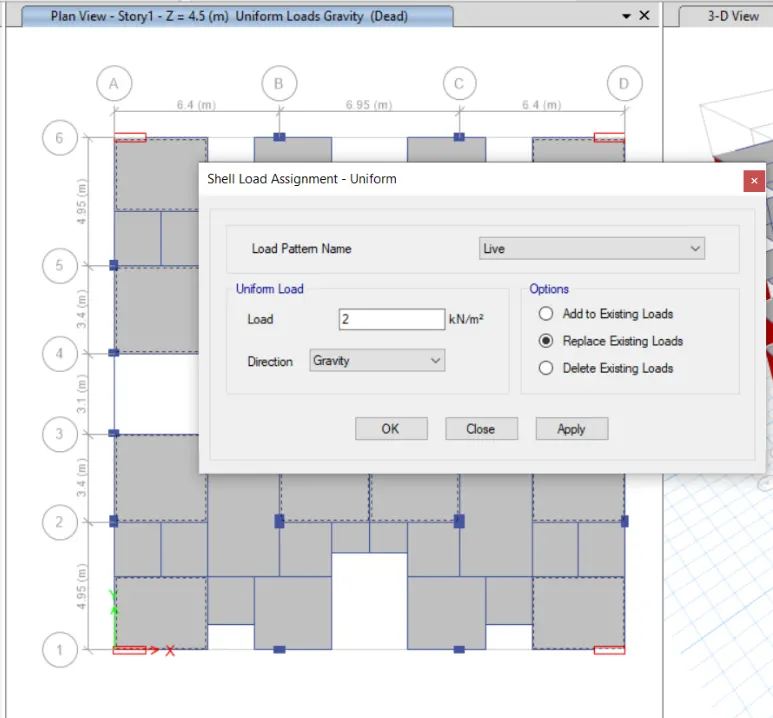
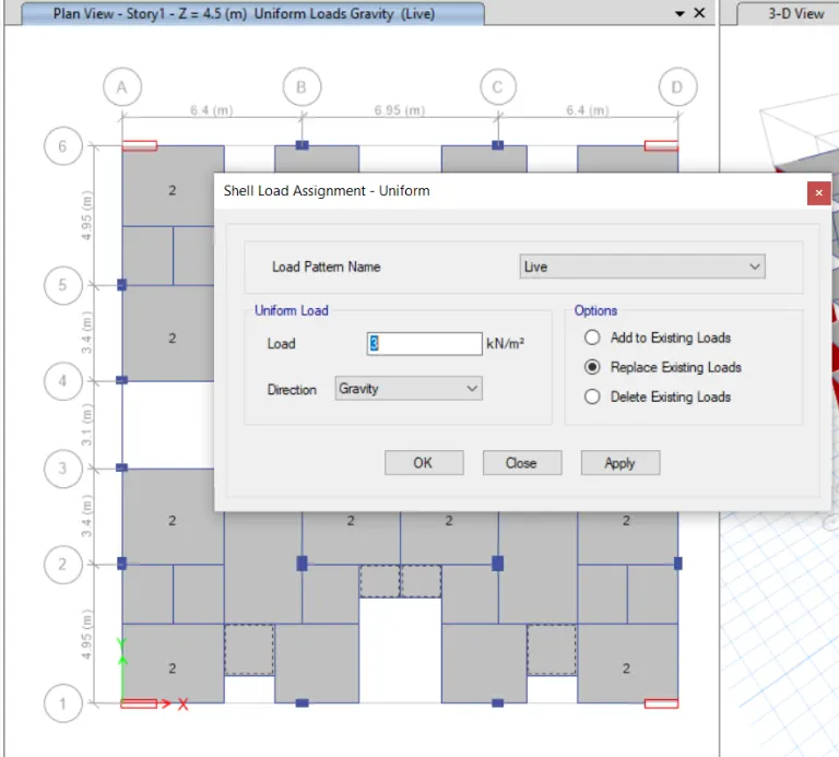
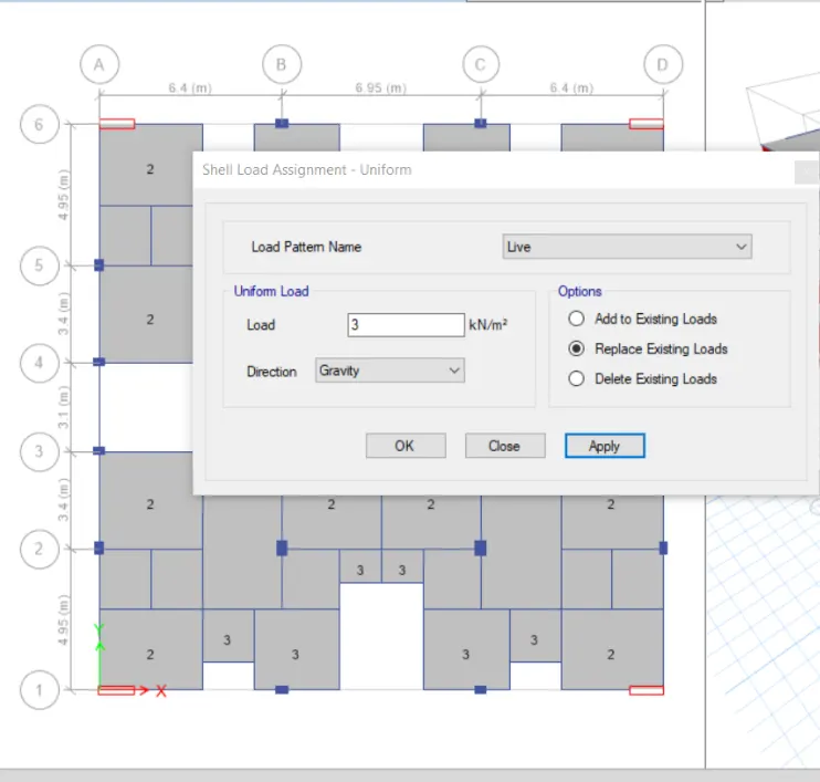
3. Apply live load for bedroom 2 KN/m^2, balcony 3 KN/m^2, Kitchen 3 Kn/m^2, Toilet 2 KN/m^2, drawing room 4 KN/m^2 , corridor passage and staircase 3KN/m^2 as per floor plan to the ETABS model
4. Live load for roof load provided in IS 875 (Part 2)- 1987 clause 4.1
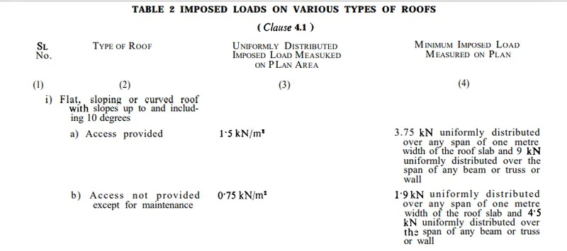
5. Apply roof load 1.5 KN/m^2 to the ETABS model
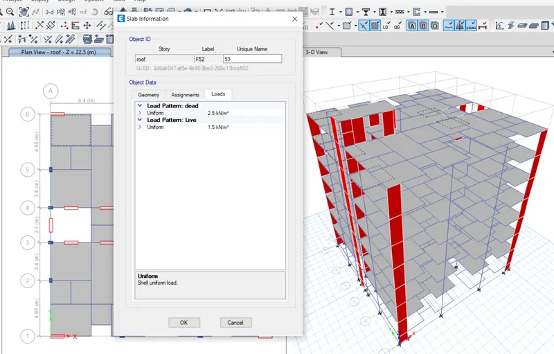
6. Calculation of dead load in slabs:-
1) Floor finish
Weight of ceiling plastering = Thickness* Unit weight = 0.015*21 = 0.315 KN/m^2
Weight of cement mortar = Thickness * Unit Weight = 0.025*21 = 0.525 KN/m^2
Weight of tiles = Thickness * Unit weight of tiles = 0.025*23 = 0.575 KN/m^2
Total weight of floor finish = 0.315+0.525+0.575 = 1.415 KN/m^2 which is approx equal to 1.5 KN/m^2
2) Roof finish
Ceiling plastering = 0.015*21 = 0.315 KN/m^2
Weathering Coarse = 0.075*23 = 1.725 KN/m^2
Cement flooring = 0.025*21 = 0.525 KN/m^2
Total weight of roof finish = 0.315+1.725+0.525 = 2.5 KN/m^2
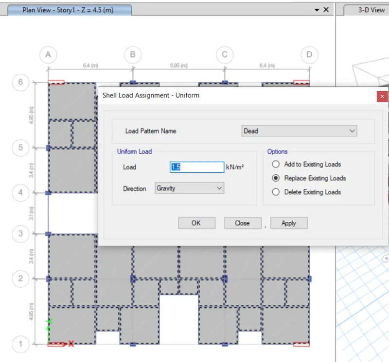
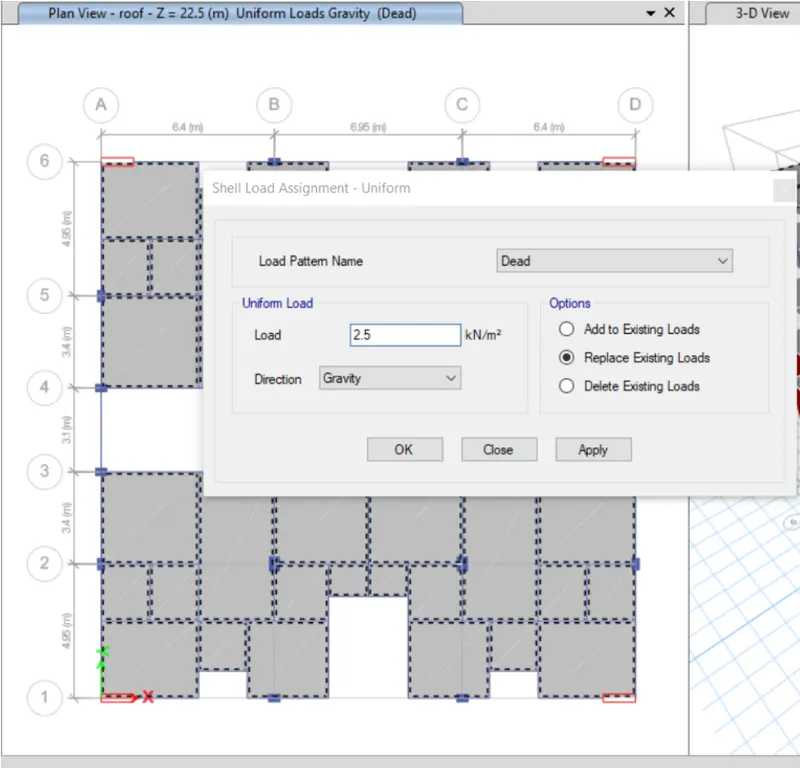
7. Apply dead load of floor finish 1.5 KN/m^2 and roof finish of 2.5 KN/m^2 to the ETABS model.
8. Calculation of brick wall load
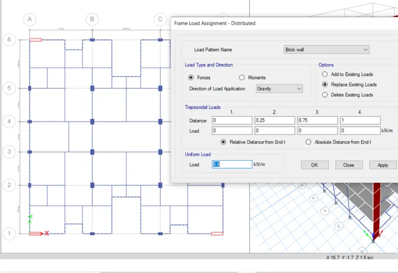
Weight of outer wall load = Unit weight of AAC bricks*Thickness*Height of wall + Unit weight*Thickness* Height of wall = 6*0.3*(3-0.45)+20*0.024*2.55 = 5.8 KN/m
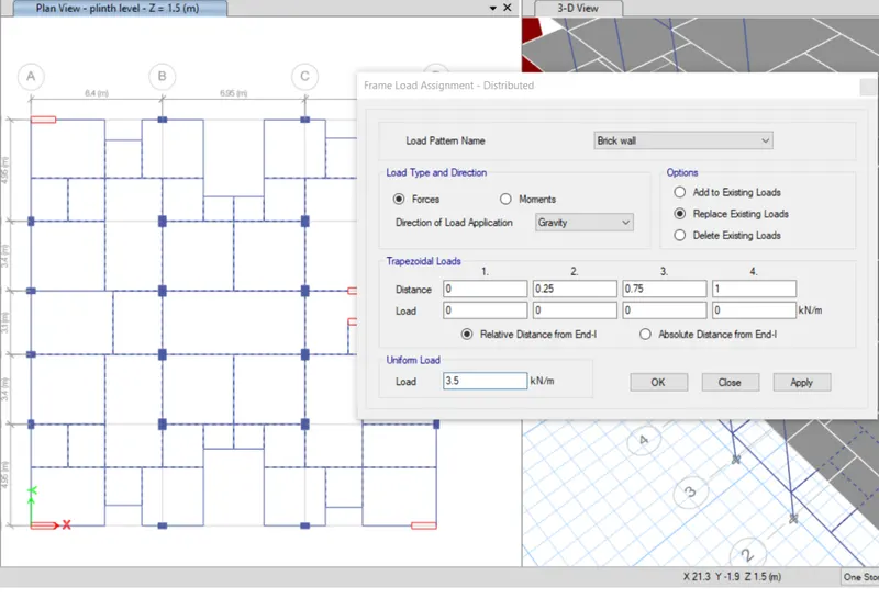
Weight of inner wall load = Unit weight of AAC bricks*Thickness*Height of wall + Unit weight*Thickness*Height of wall = 6*0.15*(3-0.45)+0.024*2.55*20 = 3.5 KN/m
9. Apply outer wall load of 5.8 KN/m and 3.5 KN/m to the ETABS model
9. Calculation of parapet load
Consider height of wall = 1.2 m
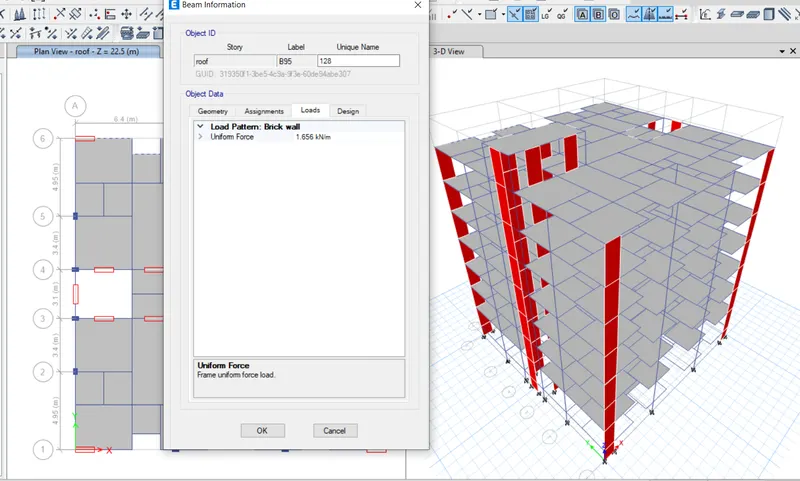
Weight of parapet wall = 1.2*0.15*6+0.024*1.2*20 = 1.656 KN/m
10. Apply parapet load of 1.656 KN/m to the main beam in ETABS model
11. Calculation of mumty wall load for roof ( Along grid line A-4 to B-4 and A-3 to A-3 to B-3)
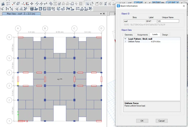
Weight of mumty load = (2.5-0.45)*0.3*6+0.024*(2.5-0.45)*20 = 4.674 KN/m
12. Apply mumty wall load of 4.674 KN/m to the main beam in ETABS model
13. Calculation of water tank
Given data: Water tank = 20 KL =20000 L = 20 m^3
Mass of water = Volume*Density = 20*10.25 = 205 KN
Consider length of tank = 5 m
Width of tank = 2.5 m
Area of water tank = 5*2.5 = 12.5 m^2
Height of tank = Volume/Area = 20/12.5 = 1.6 m
Dead load per unit area = 205/12.5 = 16.4 KN/m^2
Weight of mortar, water proofing etc = 4 KN/m^2
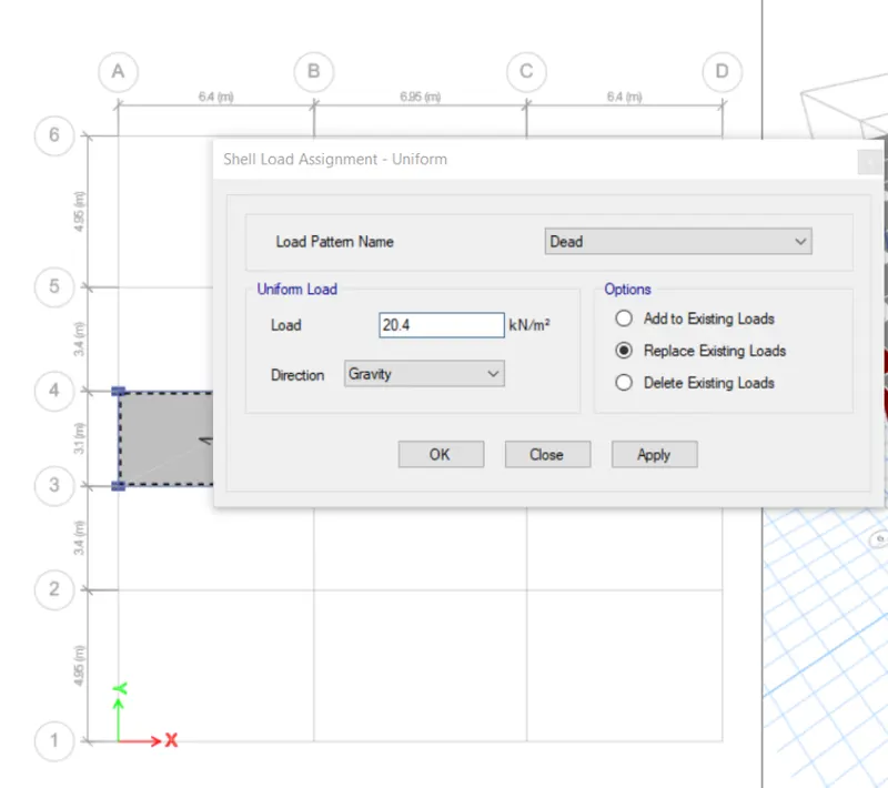
Toad dead load on base slab = 16.4+4 = 20.4 KN/m^2
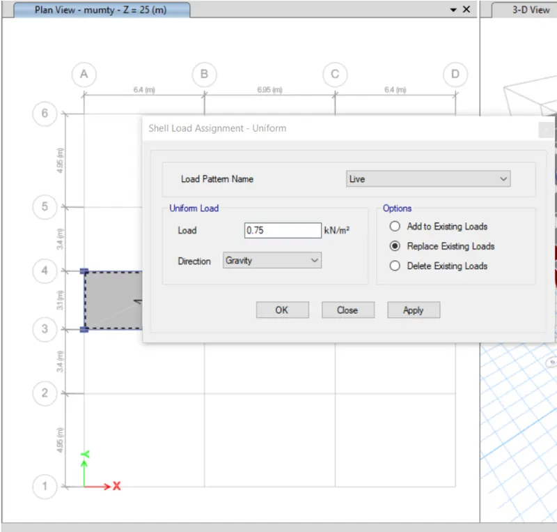
Live load on base slab as per IS 875 (Part 2-1987) = 0,75 KN/m^2
Thickness of overhead water tank = 300 mm = 0.3 m
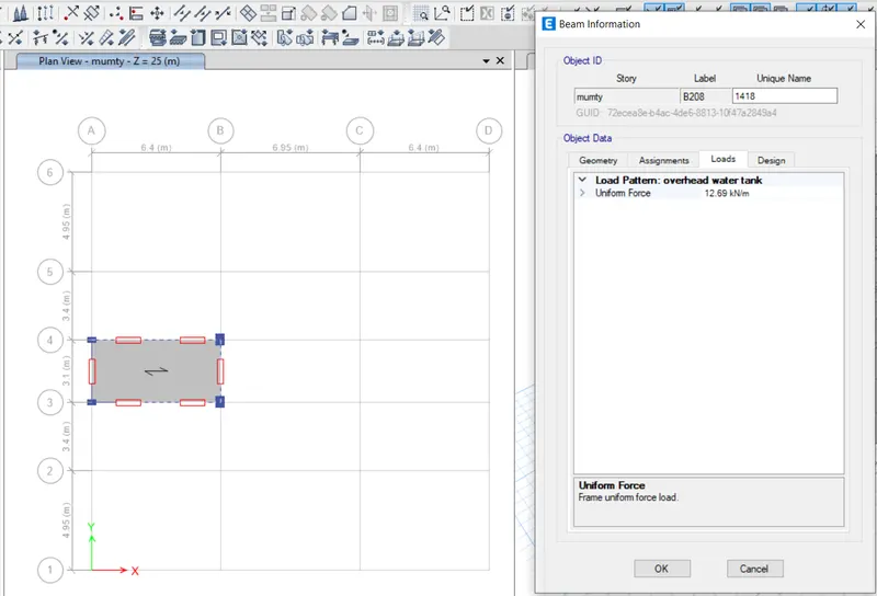
Dead load on beam = (20.4+0.75)*0.3*2 = 12.69 KN/m
14. Apply dead load of 20.4 KN/m^2 to the base slab in ETABS model
Apply live load of 0.75 KN/m^2 to the base slab in ETABS model
Apply load of 12.69 KN/m to the main beam in ETABS model
b) Earthquake load calculations
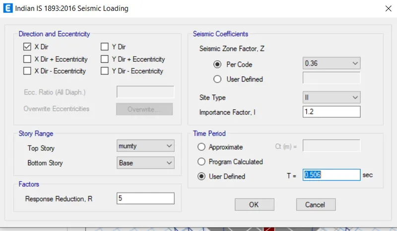
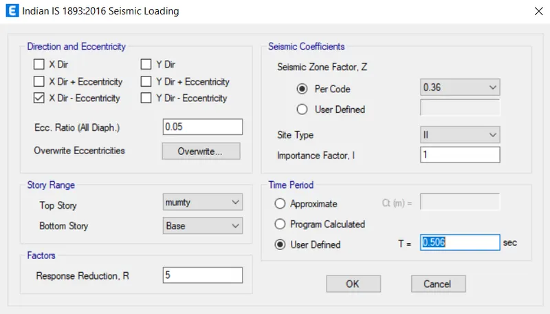
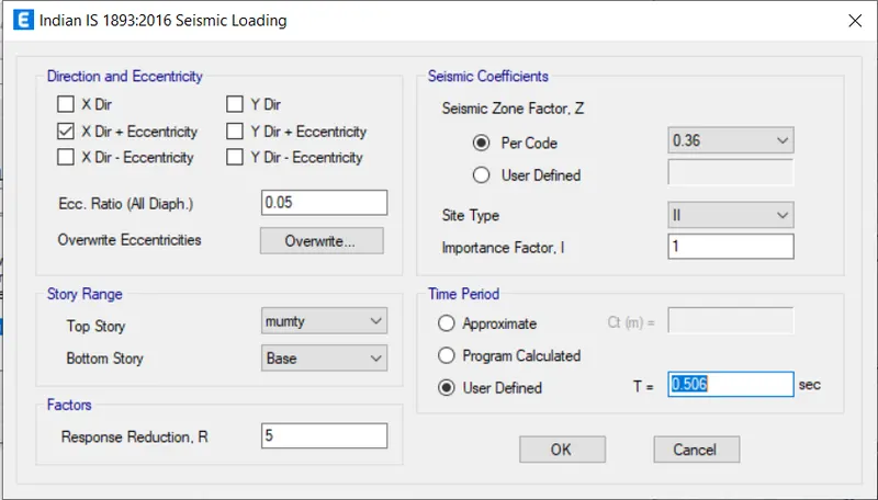
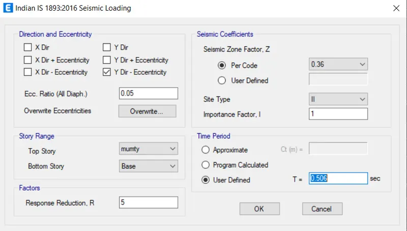
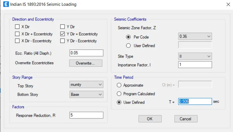
1. Calculation of time period along X direction:-
Height of the building = 25 m
Dimension of the building along x direction = 19.75 m
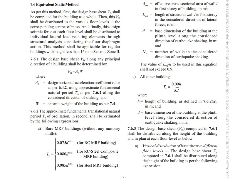
Time period, t = 0.09*h/`sqrt`d = 0.09*25/`sqrt`19.75 = 0.506 s
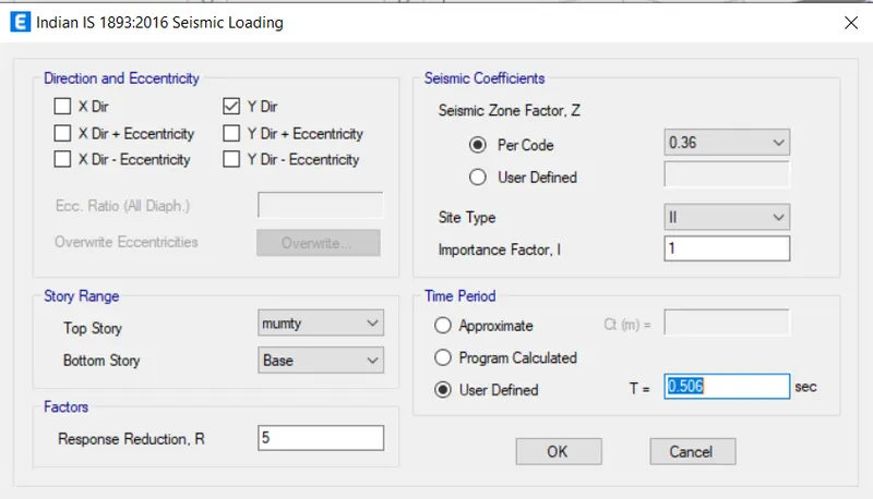
2. Calculation of time period along Y direction:-
Height of the building = 25 m
Dimension of the building along y direction = 19.8 m
Time period, t = 0.09*h/`sqrt`d = 0.09*25/`sqrt`19.8 = 0.506 s
3. Apply time period of 0.506 s to the ETABS model
c) Live load reduction factors
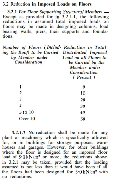
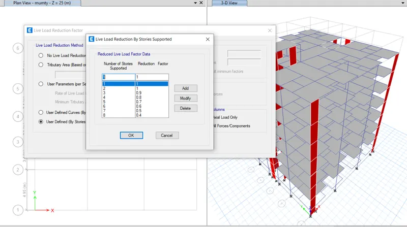
Live load has been reduced on floor as per clasue 3.2.1 on IS 875 (Part 2)- 1987
- Go to design > live load reduction factor
- Click on user and define it
d) Load combinations
Go to define > load combinations
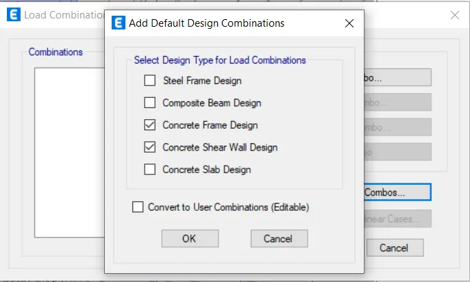
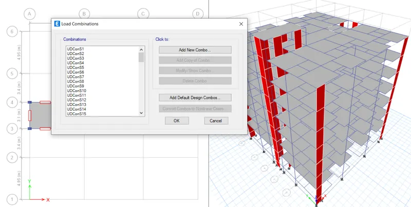
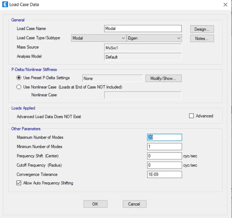
e) Model case
Click on load case
Click on modal/ show case
Maximum number of modes are to be chosen as 20
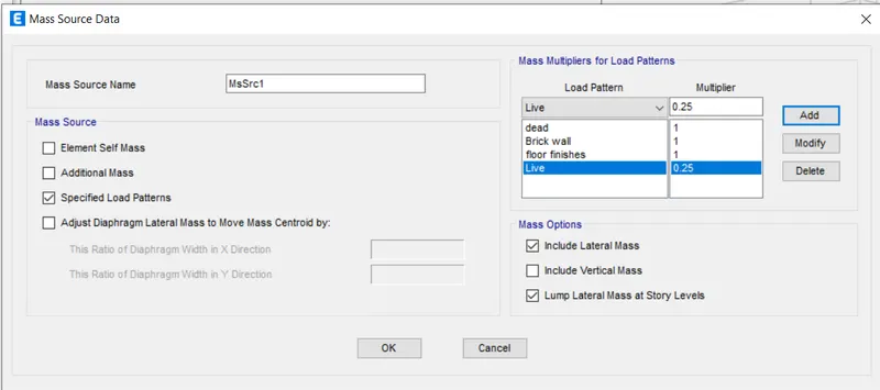
f) Mass source
Percentage of imposed loads to be considered in calculation of seismic weight is given as per clause 7.3.1 (IS 1893 Part 1 -2016)
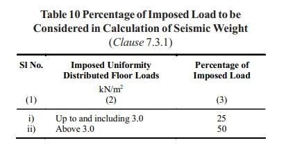
Define mass source
Click on modify mass source
Calculate percentage of dead load, brick wall and floor finishes as 100 percentage and live load as 25 percentage
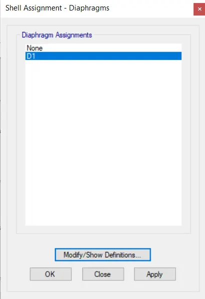
Select shell diaghram for in-plane flexibility
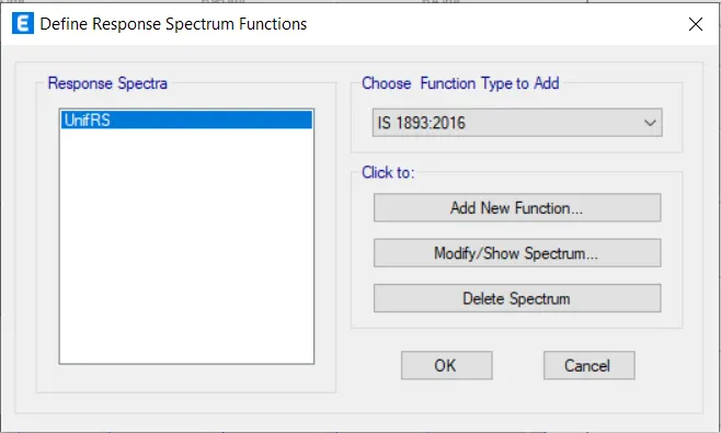
g) Respone spectrum functions
Go to define> functions> Response spectrum
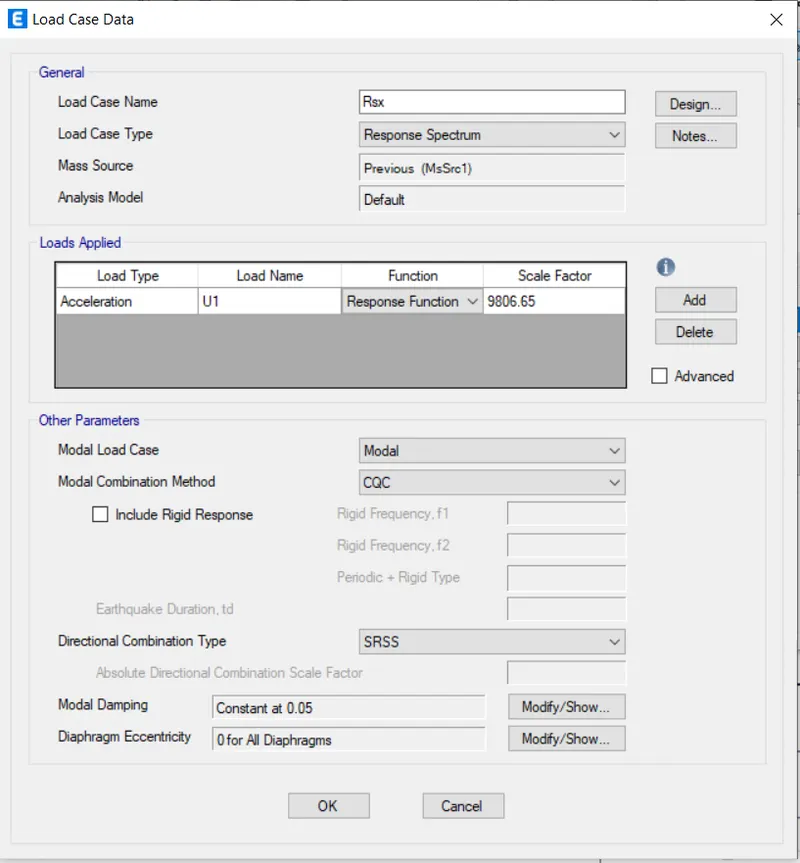
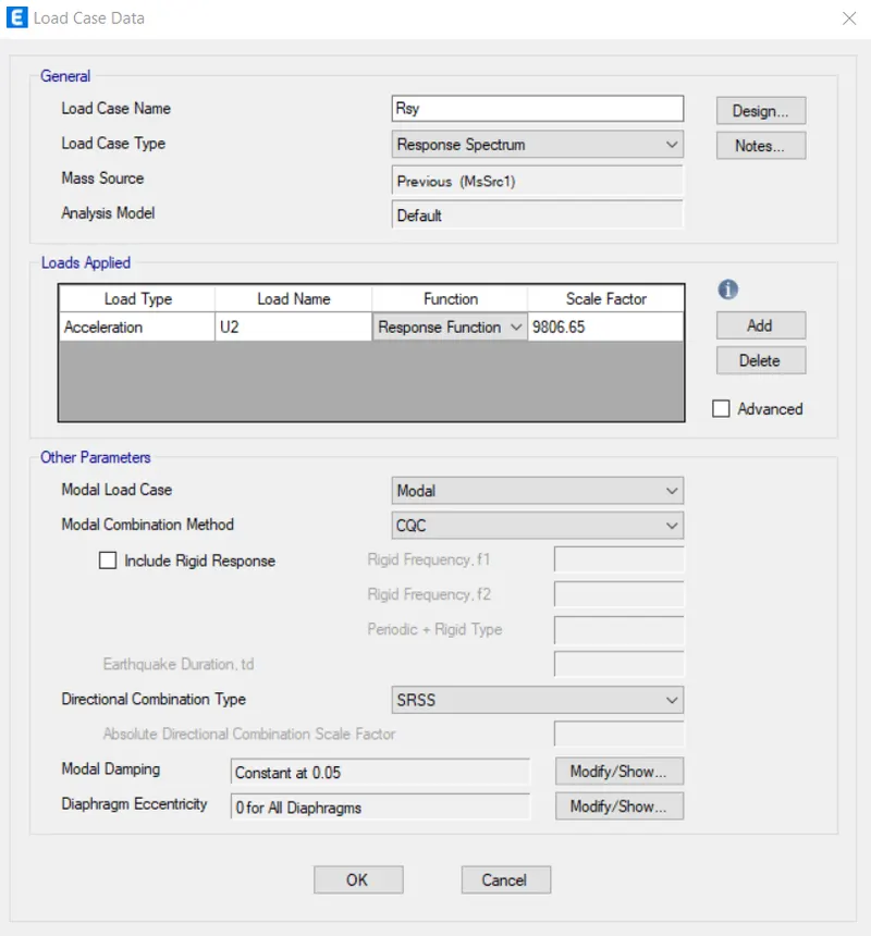
After assigning go to define load cases
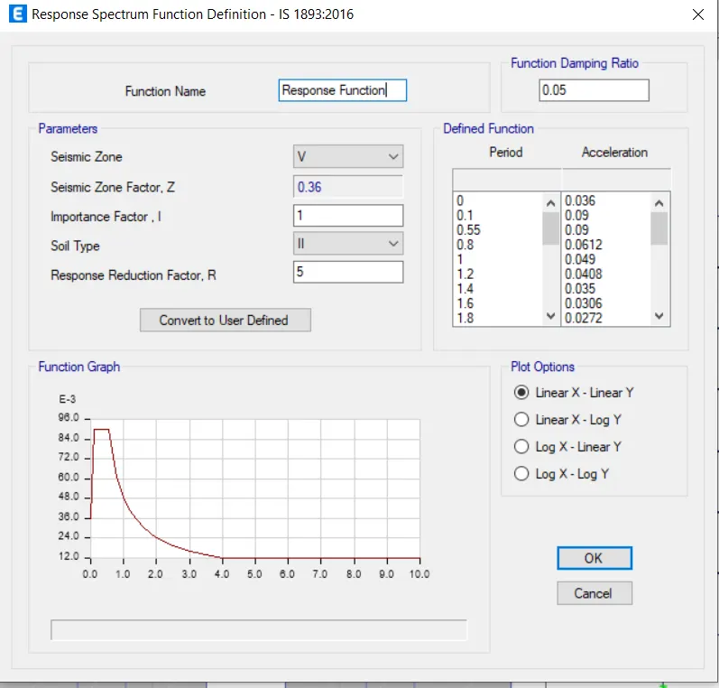
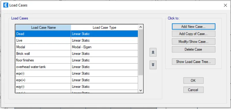
Add load case name as Rsx and Rsy for response spectrum functions in x and y axis directions respectively
h) Run Analysis
Check the model
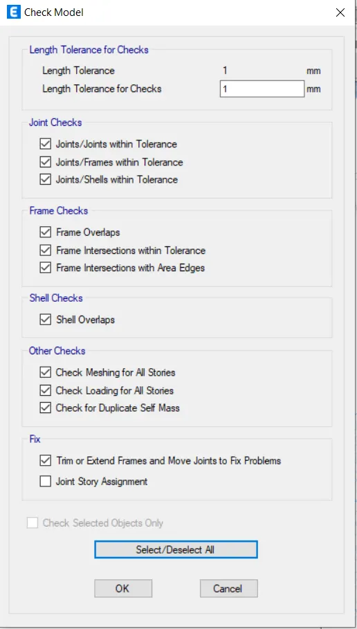
Mobel has been checked. No error messages

Run the analyis
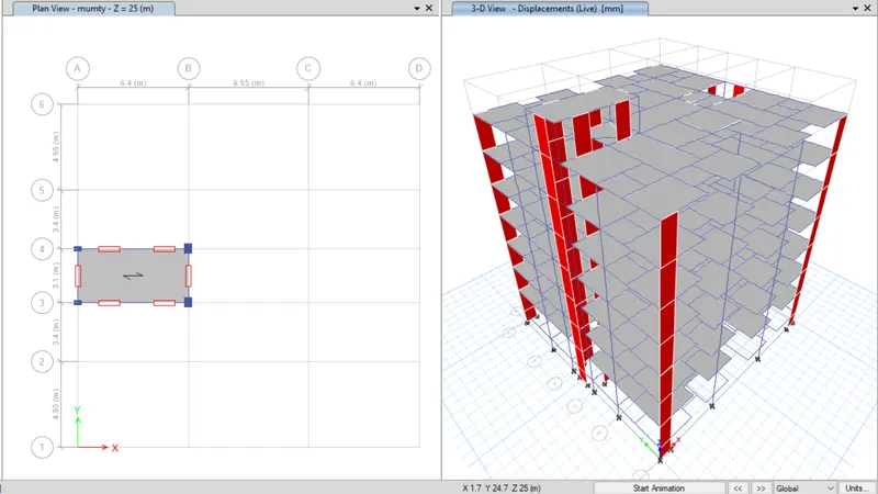
i) Output Data
A. Base shear reactions and response reduction reactions
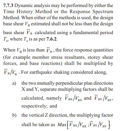
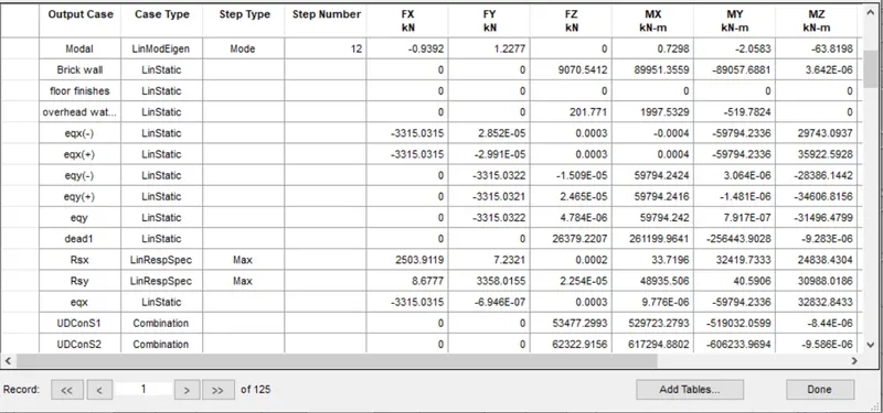
Since the linear static method and response reduction factor for base shear reactions are not same then we have to separate multiply the factors as per clause 7.7.3 (IS 1893 Part 1 - 2016)
Therefore divide (3315.0315/2503.9119) = 1.32*36402.28 (Scale factor) = 48051 in x axis
(3315.0315/3358.0155) = 0.98*43678.81 = 42805.23 in y axis
Reanalyse it and check the model
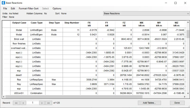
Base shear reactions in x axis for linstatic = 3484.2393 KN
Base shear reactions in y axis for linstatic = 3484.2392 KN
Base shear reactions in x axis for Response spectrum analysis = 3509.2749 KN
Base shear reaction in y axis for Response spectrum analysis = 3571.3194 KN
B. Model Participation mass ratios
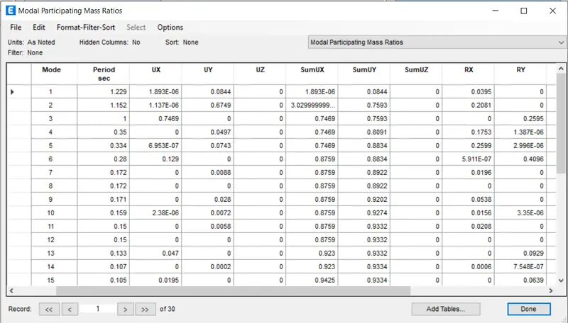
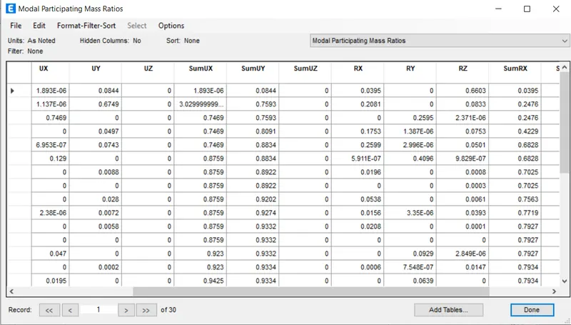
Model partcipation for first mode = 66% which is in z direction
Model participation for second mode = 75.93 % which is in y direction
Model participation for third mode = 74.69 % which is in x axis
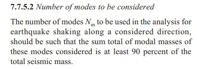
First and second modes atleast differ by 10 percent
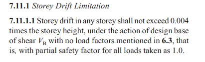
C. Inter story drift limitations
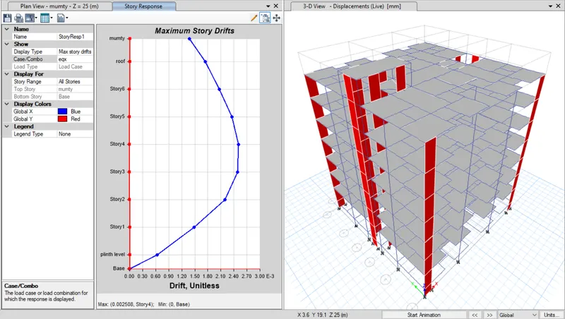
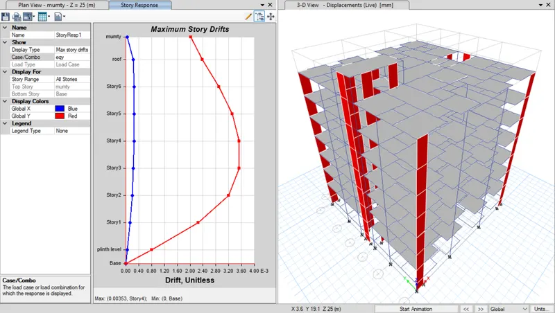
D. Minimum shear wall requirements
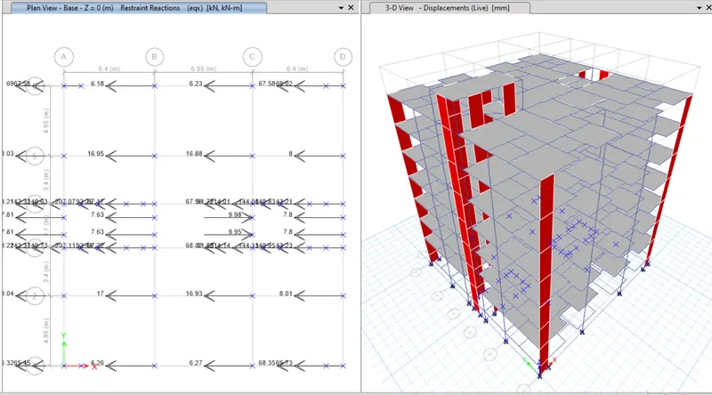
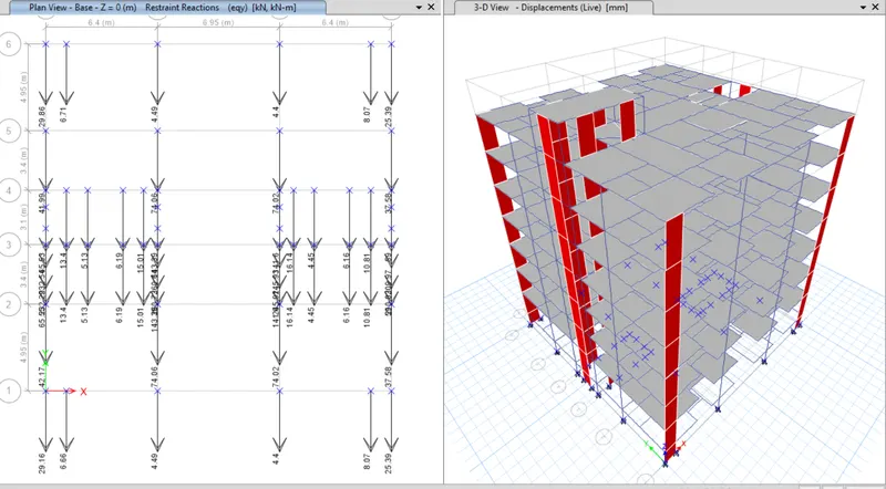
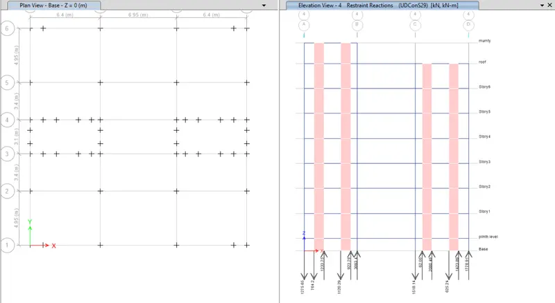
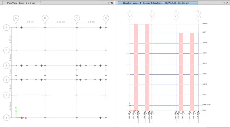
Total base shear reactions for individual shear wall in x axis = 2953.58 KN
Total base shear reactions in x axis = 3463.82 KN
Percentage of base shear reactions to be carried out = (2953.78/3463.82)*100 = 85.27% > 80% which is OK
Total base shear reactions for individual shear wall in y axis = 2390.85 Kn
Total base shear reactions in y axis = 3487.57 KN