Week 9 - Parametric study on Gate valve.
AIM: To perform a parametric study on the gate valve simulation by setting the opening from 10 % to 80%.
OBJECTIVE:
- Obtain the mass flow rates at the outlet for each design point.
- Calculate the flow coefficient and flow factor for each opening and plot the graph.
- Discuss the results of the mass flow rate and flow coefficient.
THEORY AND EXPLANATION:
GATE Valves:
A gate valve is generally used to completely shut off fluid flow or, in the fully open position, provide full flow in a pipeline. Thus it is used either in the fully closed or fully open positions. A gate valve consists of a valve body, seat and disc, a spindle, gland, and a wheel for operating the valve. The seat and the gate together perform the function of shutting off the flow of fluid.Gate valves are generally not suitable for regulating flow or pressure or operating in a partially open condition. For this service, a plug valve or a control valve should be used. It must be noted that because of the type of construction a gate valve requires many turns of the hand wheel to completely open or close the valve. When fully opened, gate valves offer little resistance to flow and its equivalent length to Diameter ratio (L/D) is approximately .
TYPES OF GATE VALVES:
There are three ways to classify the gate valve.
1. Types of Disk
1. Solid taper wedge
2. Flexible wedge
3. Split wedge or Parallel disks Valve
2. Types of Body Bonnet Joint
1. Screwed Bonnet
2. Bolted-Bonnet
3. Welded-Bonnet
4. Pressure-Seal Bonnet
3. Types of Stem movement
1. Rising Stem or OS & Y Type (Outside Stem and Screw Type)
2. Non-rising Stem type
FLOW FACTOR:
A Flow Factor (Kv) is the flow coefficient in metric units that is defined as the flow rate in cubic meters per hour (m3/h) of water at a temperature of 16ºC with a pressure drop across the valve or any other restricting device of 1 bar. The Kv is related the head drop (Δh) or pressure drop (ΔP) across the valve with the flow rate (Q).
FLOW COEFFICIENT:
Valve Flow Coefficient (Cv) is a valve’s capacity for a liquid or gas to flow through it. It is technically defined as “the volume of water at 60°F (in US gallons) that will flow through a valve per minute with a pressure drop of 1 psi across the valve.” In simpler terms, the larger the opening in a valve, the larger the Cv. As a valve is opening, the Cv increases until the valve is fully open, where it reaches its highest possible Cv, or 100% open Cv.
GEOMETRY:
The gate valve model is designed in design softwares like CATIA or Solidworks and is imported to spaceclaim for the simulation. The gate valves are the device which is primarily designed to start or stop the flow.
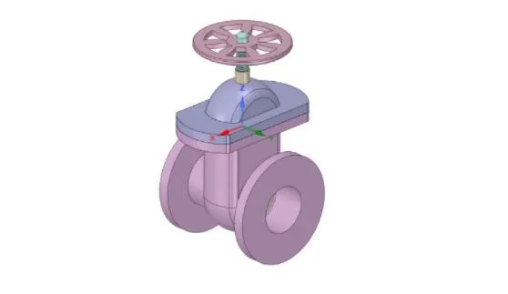
EXTRACTED FLUID VOLUME OF GATE VALVE:
Using pull tool extend both sides with 800mm.
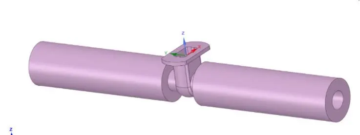
Supress all geometric parts except fluid volume:
MESHING:
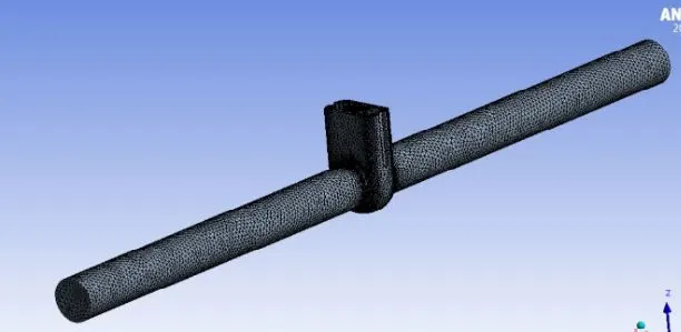
Element Size:- 5.5 mm
Number of Element:- 490898
CASE SETUP:
Geometry:
1. Solver - Pressure Based
2. Time - Steady State
Model:
1. Viscous - K -Epsilon - Realizable - Scaleable Wall Function
Material:
1. Fluid - Water
GRAVITY:
ENABLED: -9.81 m/s^2 w.r.t Z-axis
Boundary Condition:
1. Inlet - Pressure Inlet - Gauge Pressure - 10 Pa
Method:
1. Scheme - Coupled
2. Initialization - Standard from Inlet
3. Number of Iteration - 300
RESULTS:
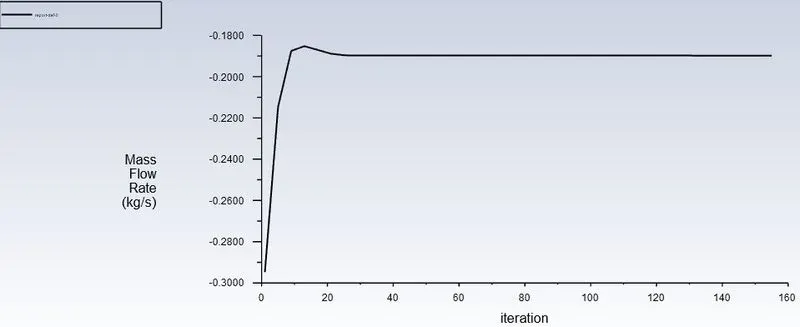
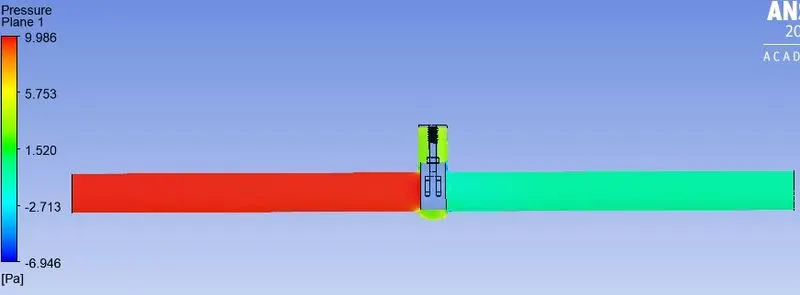
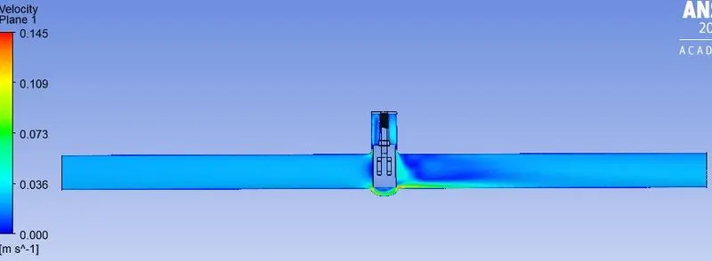
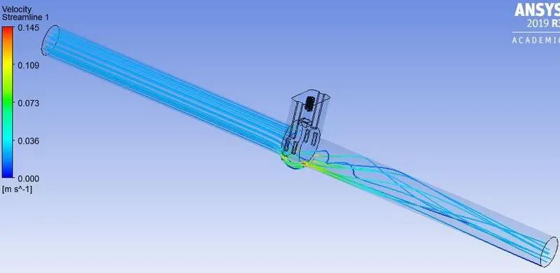
CASE1: FOR 15 mm
RSIDUALS PLOT:
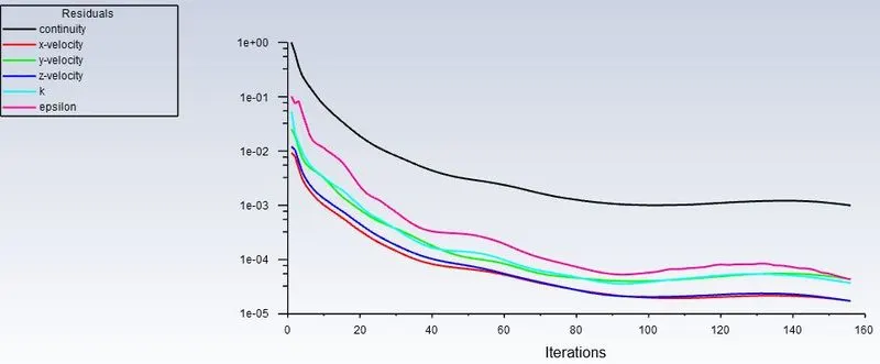
MASS FLOW AT OUTLET:
PRESSURE CONTOUR:
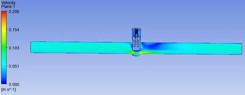
VELOCITY CONTOUR:
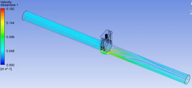
STRAM-LINE FLOW:
CASE2: FOR 20 mm
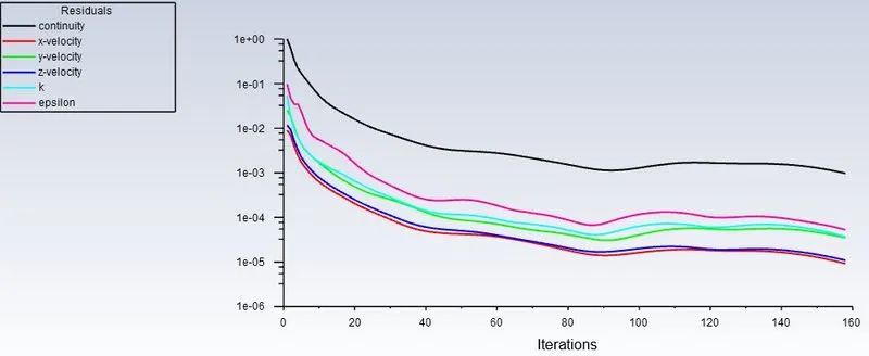
RSIDUALS PLOT:
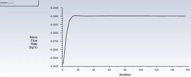
MASS FLOW AT OUTLET:
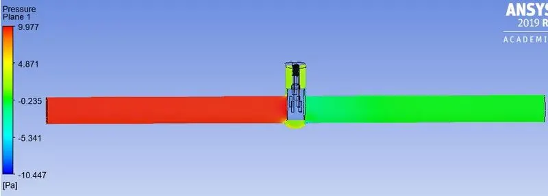
PRESSURE CONTOUR:
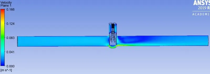
VELOCITY CONTOUR:
STRAM-LINE FLOW:
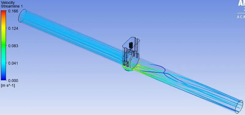
CASE3: FOR 25 mm
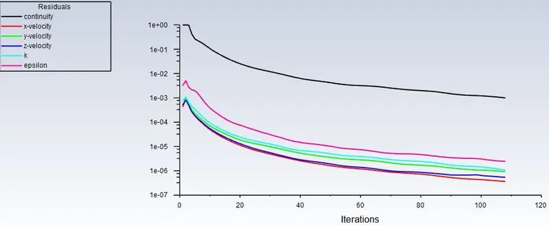
RSIDUALS PLOT:
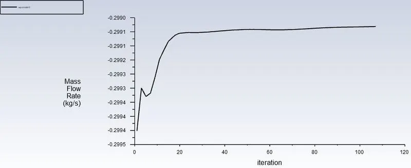
MASS FLOW AT OUTLET:
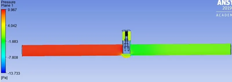
PRESSURE CONTOUR:
VELOCITY CONTOUR:
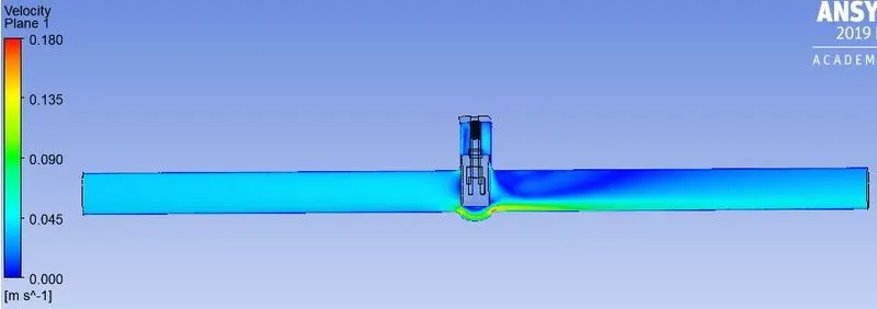
STRAM-LINE FLOW
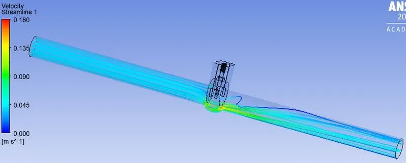
CASE4: FOR 30 mm
RSIDUALS PLOT:
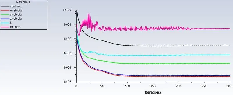
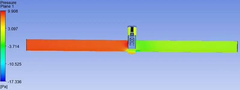
PRESSURE CONTOUR:
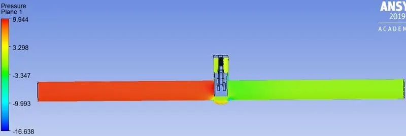
VELOCITY CONTOUR:
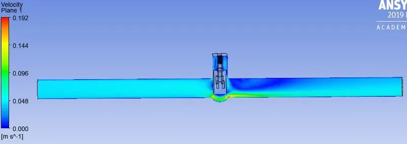
STRAM-LINE FLOW:
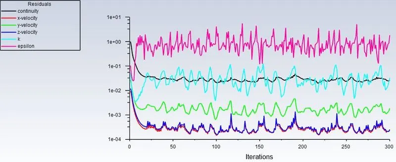
CASE5: FOR 35 mm
RSIDUALS PLOT:
PRESSURE CONTOUR:
VELOCITY CONTOUR:
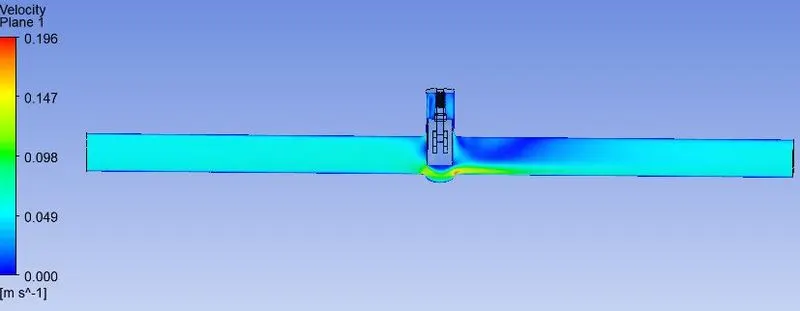
STRAM-LINE FLOW:
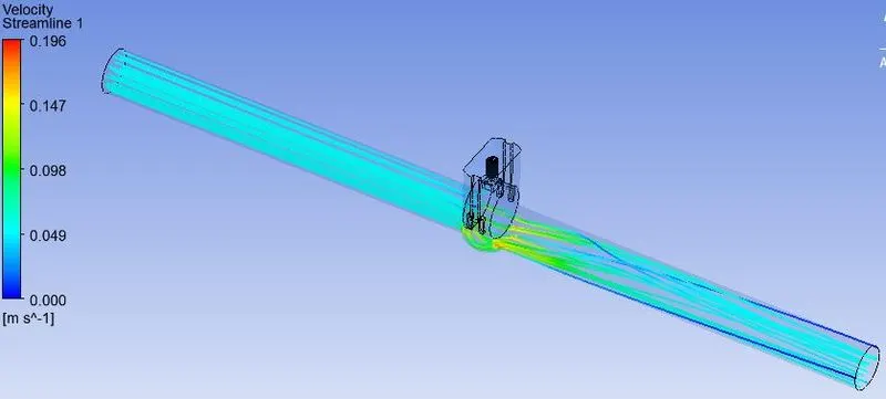
CASE6: FOR 40 mm
RSIDUALS PLOT:
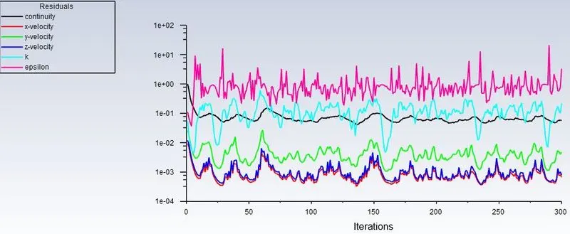
PRESSURE CONTOUR:
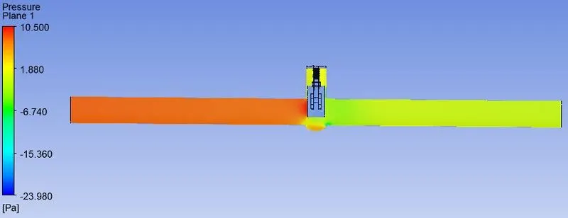
VELOCITY CONTOUR:
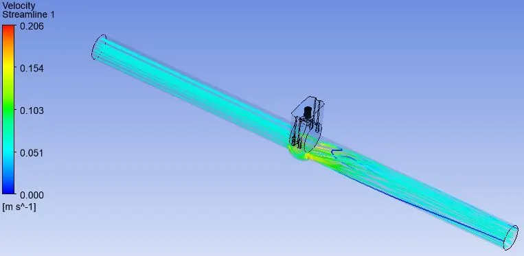
STRAM-LINE FLOW:
AT OUTLET:
FLOW COEFFICIENT:
The Flow Coefficient of a device is a relative measure of its efficiency at allowing fluid flow.
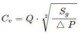
Where,
Q is Mass flow rate
Sg is specific gravity of water which is 1
△ P is pressure drop (in PSI)
FLOW FACTOR:
The metric equivalent flow factor is calculated using
Kv = 0.865 ⋅ Cv
Q is Mass flow rate
Sg is specific gravity of water which is 1
△ P is pressure drop (in PSI)
AT INLET:
FLOW FACTOR AND FLOW COEFFICIENT IS:
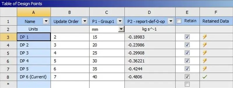
To identify the flow is laminar to Turbulent
For circular pipe:
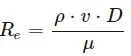
For Laminar Pressure drop:
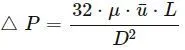
Gate disk opening can be calculated as shown in below table:
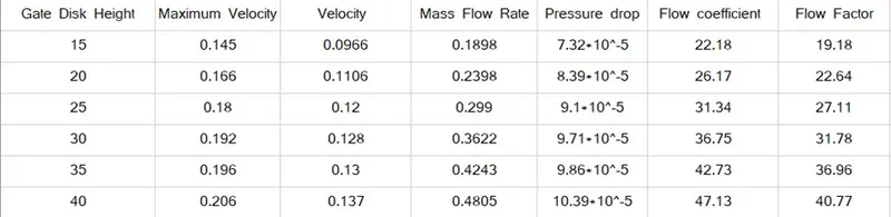
Graph for Flow Coefficient and flow factor:
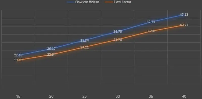
Parametric table for mass flow rate:
CONCLUSION:
- As the mass flow increase with opening of gate valve disk, thus the fluid through the pipe will also increase.
- As the gate disk open, the velocity increase and pressure drop decrease and therefore mass flow rate and flow coefficient increase.
- The flow coefficient is used to determine the valve size that will best allow the valve to pass the required flow rate which provide stable control of process fluid.
- Due to high velocity and decrease in pressure drop there is formation of cavitation in the liquid system.
- Pressure drop, the liquid state to boil and produce vapour bubble creating vapour pressure causing high pressure waves.
- These implosion result in very high noise level.