Week - 4
1.
AIM: To implement control logic of a “washing machine” using Stateflow as per given sequence and the following simulations shoould be done as follows:
- If the power supply is available, the system gets activated.
- If the Water supply is not available, stop the process & indicate through LED.
- Soaking time should be 200s followed by Washing time of 100s.
- Then rinsing happens for next 20s & dryer runs for 50s.
BLOCKS USED: 1. Rocker switch
2. Constant
3. Chart
4. Display
5. Lamp
LOGIC EXPLINATION: Use chart block to create logic for the washing machine.
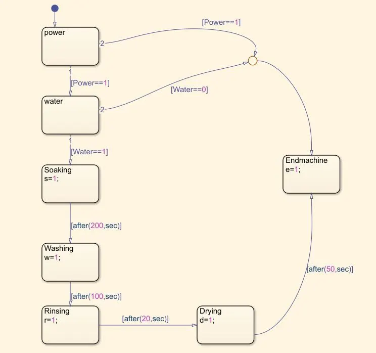
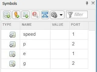
Also use the symbols pane to define variables define this model
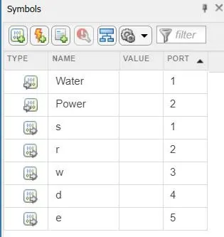
EXPLANATION AND RESULTS:
1. We use the constant blocks which represents the 1,0 values included in it i.e., the supply should be on or off.
2. Then the rocker switch in which the connections are made to two constant blocks.
3. These constants are connected to chart block which include the washing machine control logic in it.
4. The outputs are connected to display block which tells about the derived programs are working or not in terms of 1 and 0 numericals
5. These display blocks are connected to the Lamp blocks which represents in lightning visuals.
a. If the power supply is available, the system gets activated
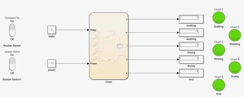
b. If the Water supply is not available, stop the process & indicate through LED
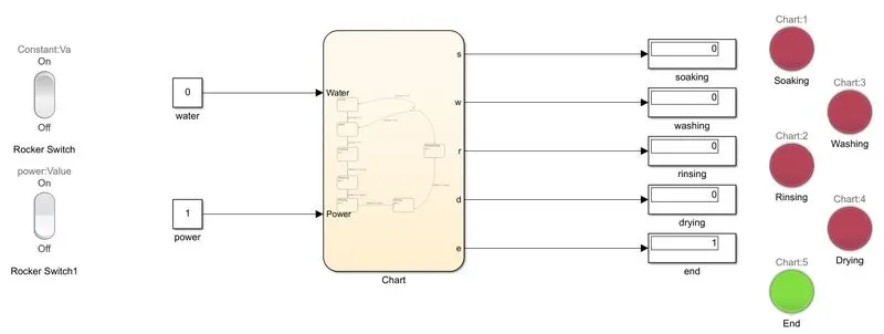
c. Soaking time should be 200s followed by Washing time of 100s
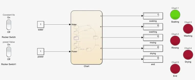
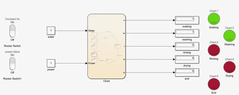
d. Then rinsing happens for next 20s & dryer runs for 50s
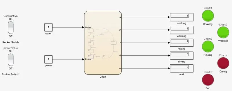
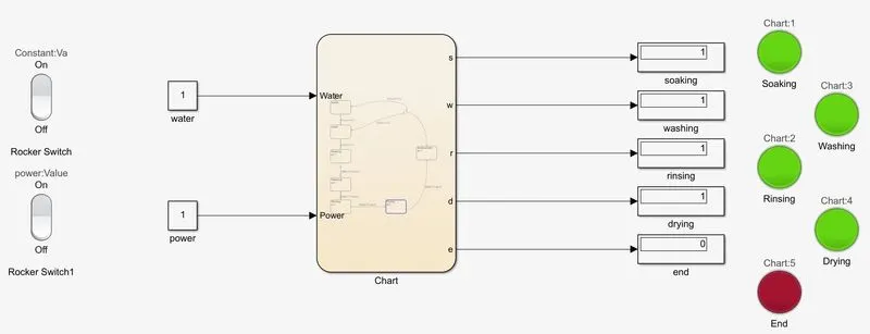
After all processes are completed the finished LED turns on
2.
AIM: TO make a Simulink chart for the “Gear shift” logic as per below conditions:
Speed Range(kmph) Gear
0 to 15 1
16 to 25 2
26 to 40 3
41 to 60 4
Above 61 5
And to give speed input while the simulation is running & display the gear number.
BLOCKS USED: 1. Slider gain
2. Constant
3. Rocker switch
4. Scope
5. Chart
6. Display
7. Lamp
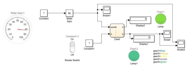
SIMULINK MODEL:
GEARBOX LOGIC CHART:
SYMBOLS PANE:
SPEED REPRESENTATION THROUGH COLORED LAMPS:
GEAR1= BLUE-0 TO 15 RANGE
GEAR2= ORANGE-16 TO 25 RANGE
GEAR3= YELLOW-26 TO 40 RANGE
GEAR4= PURPLE-41 TO 60 RANGE
GEAR5= GREEN- ABOVE 61 RANGE
EXPLANATION AND WORKING:
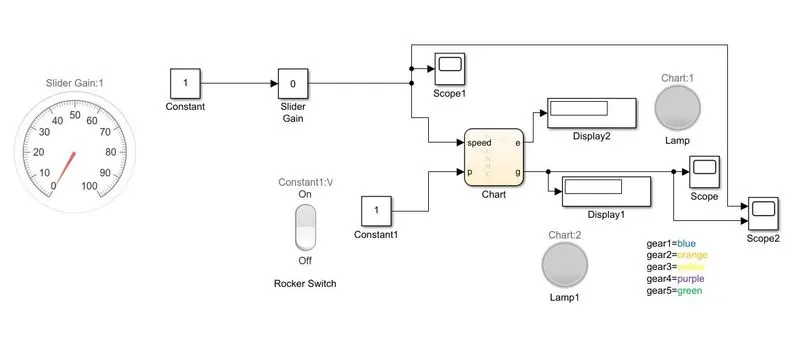
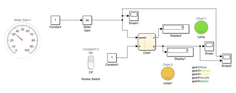
1. The constant block is connected to the slider gain and the required speed range is operated by giving input parameters on our own.
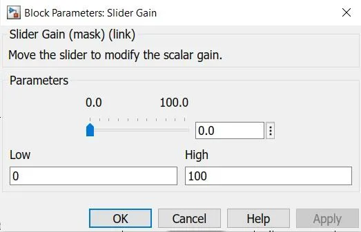
2. In another the rocker switch is connected to p on flow chart through the constant block.
3. The output of flow chart is connected to the display and lamp through the scope.
4. the lamp produces the different colors according to the range input.
When the power is zero or no input is provided the lamp turns to red, thus process ends.
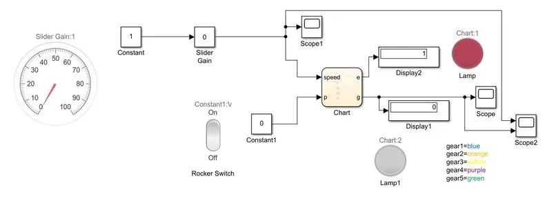
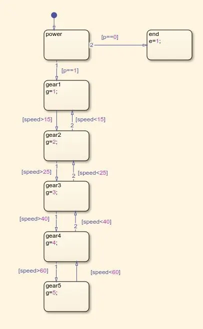
- when speed is between 0-15 range its runs on gear1
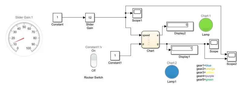
- when speed is between 16-25 range its runs on gear2
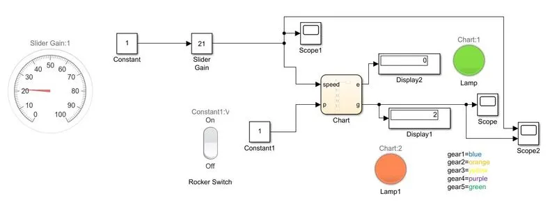
- when speed is between 26-40 range its runs on gear3
- when speed is between 41-60 range its runs on gear4
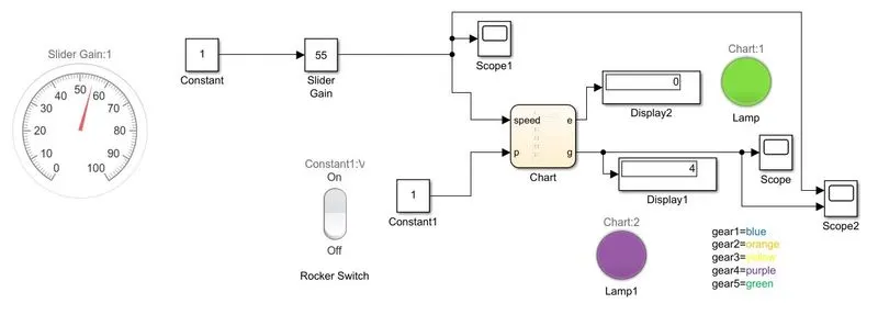
- when speed is above 60 range its runs on gear5