Week -2
1.
AIM: To make the Doorbel using Solenoid block on Simulink model basis.
Blocks used: 1. Pulse Generator
2. Simulink-PS converter
3. Switch
4. Battery
5. Electrical Reference
6. Solenoid
7. Ideal Translational motion sensor
8. Mechanical Translational Reference
9. PS-Simulink converter
10. Solver configuration
11. Scope(3)
OBJECTIVE:
DOOR BELL: Creating a simulation where the switch is closed for 2 seconds and then released.
Solenoid: A coil of wire usually in cylindrical form that when carrying a current acts like a magnet so that a movable core is drawn into the coil when a current flows and that is used especially as a switch or control for mechanical device.
Simulink Model:
Explination:
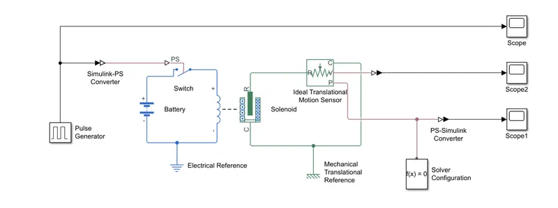
1. From the above Simulink diagaram of doorbell, we coonect the blocks from library browser as to obtain the results.
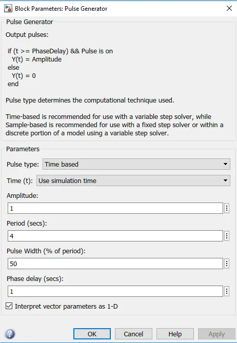
2. We take the pulse Generater and connect it to the Simulink-PS converter. Now to provide a physical signal for operating the switch, we have used a ‘Pulse Generator Block’, which generates a continuous square pulse.
Inputs to pulse generater:
3. Now first we take the Solenoid Block to represent a solenoid in the model, then for the battery we have taken Battery Block from the library browser. Then this Solenoid Block and Battery Block are connected to each other via positive and negative terminals.
4. A PS ported Switch Block is placed in between Solenoid Block and Battery Block as it connected with both the blocks.
5. Now this whole battery, switch and solenoid path is connected to an ‘Electrical Reference Block’ which represents earthing
of the circuit.
6. Then in the Solenoid Block, R and C are two variables which represent plunger and fixed point respectively. Now this R is connected to a R of Ideal Translation Motion Sensor Bock, which senses the position of the plunger in the Solenoid Block and gives the output.
7. Now in Ideal Translation Motion Sensor Bock the outputs are given as V and P which represent the velocity and position
of the plunger. And C in the Ideal Translation Motion Sensor Bock is a mechanical translation conserving port, which means that the mechanical process starts from ‘R’ and ends at C and again it starts at R and the cycle goes on.
8. The C in the Ideal Translation Motion Sensor Bock is connected to a Mechanical Translation Reference which represents a
fixed point where it is rigidly clamped in real time.
9. The plunger is output from ideal Translation Motion Sensor Bock, So we have connected port P to a PS–Simulink Converter where the physical values from port P are converted into Simulink value, then this PS-Simulink Converter is connected to Scope Block which will generate a graph for change in position of plunger from port P of Ideal Translation Motion Sensor Bock.
RESULTS:
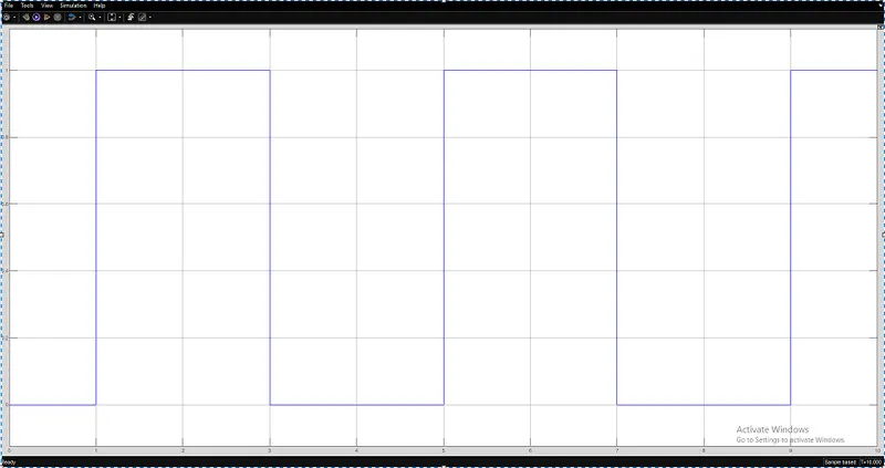
TIME Vs AMPLITUDE:
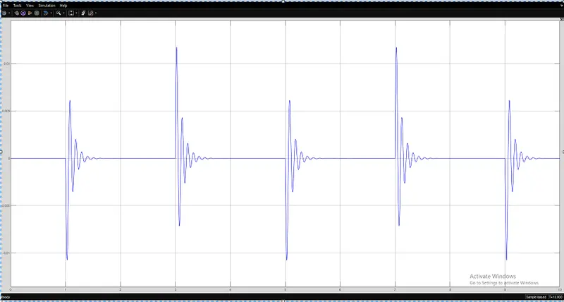
TIME Vs VELOCITY:
TIME Vs POSITION:
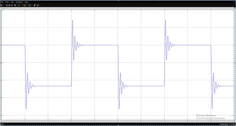
CONCLUSION:
Finally we conclued that, When the pulse generator amplitude is 1 then the plunger will moved and when the amplitude returns to 0 the plunger moves to the original position and in this time interval, beause of low damping value it undergoes several oscillations before coming to the original position.
2.
AIM: To make the Simulink model using a thermistor to sense the temperature of a heater & turn on or turn off the fan.
BLOCKS USED: 1. Signal builder
2. Simulink-PS converter
3. Controlled temperature source
4. Temperature source
5. Thermistor
6. Battery
7. Resistor
8. Electrical reference
9. Solver configuration
10. Voltage source
11. Switch
12. Constant
13. PS-Simulink converter
14. Scope
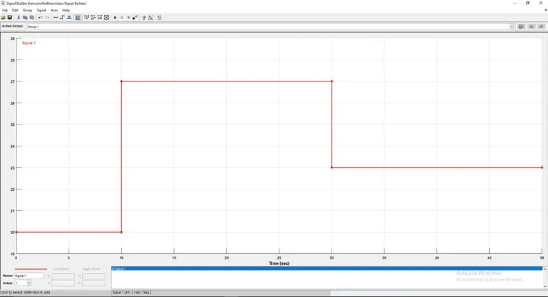
OBJECTIVE: Creating the simulation for temperature source 20 °C from 0 to 10 seconds, 27 °C from 10 to 30 seconds, 23 °C from 30 to 50 seconds and fan conditions is ON if the temperature above 25 °C, OFF otherwise.
THERMISTOR: Thermistors change resistance with temperature changes; they are temperature-dependent resistors. They're perfectly suited to scenarios where one specific temperature needs to be maintained, they're sensitive to small changes in temperature. They can measure liquid, gas, or solids, depending on the type of thermistor.
Thermistors are of two types:
NTC thermistors: In this resistance decreases as temperature rises. It is commonly used as a temperature sensor, or in series with a circuit as an inrush current limiter.
PTC thermistors:In this resistance increases as temperature rises. It is commonly installed in series with a circuit, and used to protect against overcurrent conditions, as resettable fuses.
In this we are using NTC type of Thermisters.
EXPLINATION:
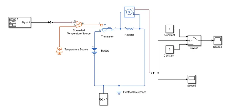
1. A signal builder block is used to achieve the given temperature source.
2. Controlled Tempearature Source is an ideal energy source in a thermal network that can maintain a controlled temperature difference regardless of heat flow.
3. A NTC thermistor is used to sense the tempearature change .A reference resistor is used in series to measure the voltage drop change as temperature change.
4. Here the Voltage sensor is used to measure the voltage drop and generate an output signal given to the logic circuit to turn on/off the fan.
Simulink Model:
5. Double click on the Signal Builder Block to set the signal according to the requirement.
6. Now the output of the Voltage Sensor Block is connected to Scope Block first, and before connecting to the Scope Block a PS-Simulink Converter is used to convert physical value to Simulink values by running the simulation and double click on the ‘Scope Block’ we will get the following the graph.
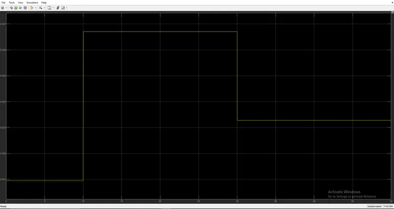
RESULTS:
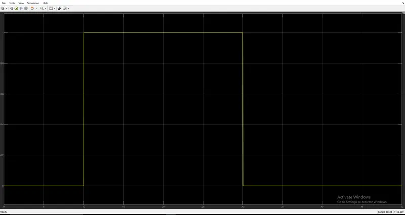
CONCLUSION:
Finally we conclude that, it the temperature attains 27°C from 10-30 the fan is in ON condition and at above and below temperature conditions the fan is in OFF condition.