Week 12:Project 2-Meshing of Rear Wheel Holder challenge
AIM: To extract the midsurface of the given geometry and assign the property card to it.
OBJECTIVE:
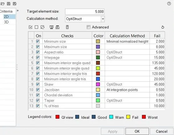
Follow the below-mentioned quality criteria, mesh the component given below and assign thickness:
Target Element Length = 5 Units
| S.N | Quality Criteria | Value |
| 1 | Aspect Ratio | 5 |
| 2 | Skewness | 45 |
| 3 | Warping | 15 |
| 4 | Taper | 0.5 |
| 5 | Min. Length | 2 Units |
| 6 | Max. Length | 8 Units |
| 7 | Min angle Quad | 45 |
| 8 | Max angle Quad | 135 |
| 9 | Min angle Tria | 20 |
| 10 | Max angle Tria | 120 |
| 11 | Tria % |
10 |
EXPLANATION:
1. Import the given IGES. geometry file into Hypermesh.
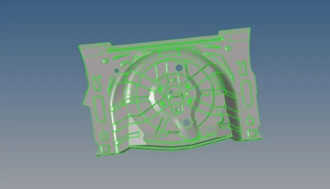
2. The given component has few geometrical errors which are to be fixed manually so that to generate perfect midsurface of the component.
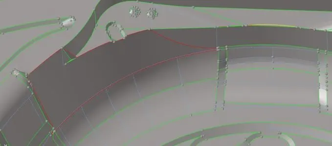
3. The given problem can be fixed by replacing the lines and using fillers surface which is present in quick edit submenu of geometry toolbar.
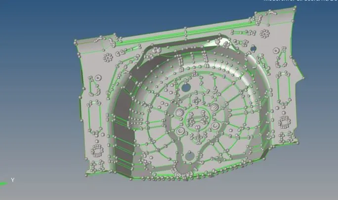
4. After geometry cleanup next, to define the criteria file which is required for meshing.
5. Generate midsurface for meshing.
6. After meshing the components consist of bad elements which does not meet the criteria.
7. These elements need to be cleaned to get the requirement meshing criteria.
8. The failed elements can be fixed using the element fixing tools in the quality criteria menu.
9. While using the quality criteria menu the failed elements are highlighted in yellow and red colours.
10. Yellow errors indicate that the errors can be fixed easily. Whereas the red colour indicate critical errors.
FINAL VIEW:
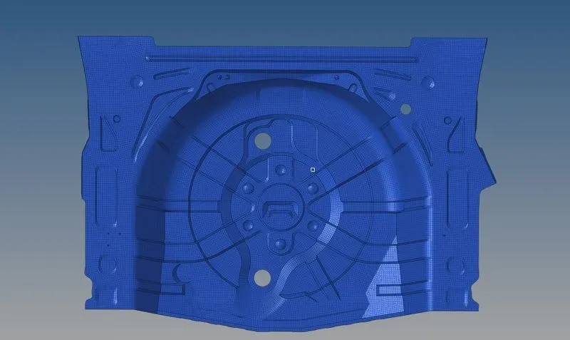
CONCLUSION:
1. Learned how to toggle the unwanted surfaces.
2. Learned how to create the manual midsurfacing.
3. Learned how to create the property card to different thickness of surfaces.