Week 11 - Simulation of Flow through a pipe in OpenFoam
AIM: To Simulate the axi-symmetric flow through a pipe by applying the wedge boundary condition on openFoam.
OBJECTIVE:
- Validate Hydro-dynamic length with the numerical result
- Validate the fully developed flow velocity profile with its analytical profile
- Validate maximum velocity and pressured drop for fully developed flow
- Post-process Shear stress and validate wall shear stress for fully developed flow
- The flow is laminar and flows through a constant cross-section pipe at an inlet Reynold's number of 2100.
THEORY AND EXPLANATION:
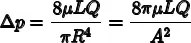
In nonideal fluid dynamics, the Hagen–Poiseuille equation, also known as the Hagen–Poiseuille law, is a physical law that gives the pressure drop in an incompressible and Newtonian fluid in laminar flow flowing through a long cylindrical pipe of constant cross section.
Eqaution for standard fluid-kinetics is,
where:
Δp is the pressure difference between the two ends,
L is the length of pipe,
μ is the dynamic viscosity,
Q is the volumetric flow rate,
R is the pipe radius,
A is the cross section of pipe
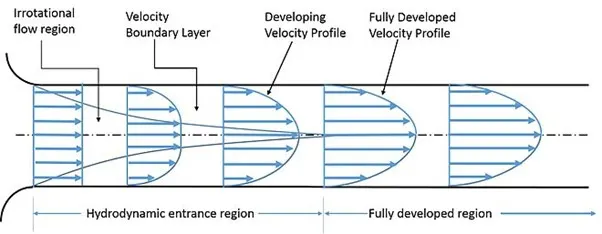
Expected Velocity Profile:
FOLLOWING ASSUMPTIONS:
- The distance the fluid has to travel to become fully developed is given by the Entry Length formula.
- Given Reynolds number is 2100. This implies flow is laminar
- Hence Entry length formula for Laminar is given by: L/d 0.06. Re
- where L is effective length; d is dia of pipe and Re is reyonolds number.
- Assuming the dia of pipe as 10mm; substituting the values, we get L = 1.2m
STEPS:
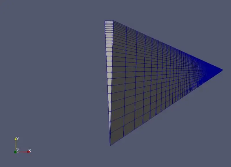
- First, the geometry is created in the blockmesh Dict file, this is done by creating the file through the matlab code.
- The mesh is generated according to requirement.
- The velocity and preassure bc are applied
- The controlDict file is edited for Simulation run time and timestep;
- After the geometry is input, the simulation can be started by calling 'icoFoam' command in the terminal.
- 'paraFoam' command helps to open paraView
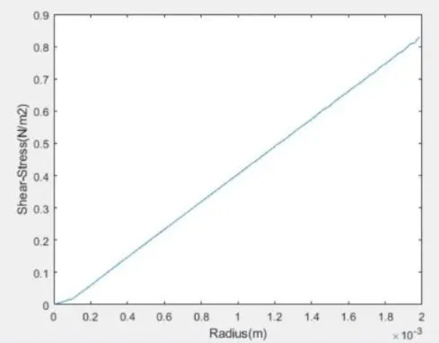
- The shear stress diagram is obtained by post-processing the velocity results obtained from Openfoam.
MATLAB PROGRAM:
BLOCKMESHDICT FILE:
 clc
 clear all
 close all
 % variable values
 D = 0.01;
 r = D/2;
 L = 1.2;
 theta = input(' input the value of wedge angle=');
 % String for header,
 h1 =' /*---------------------------------*- C++ -*-------------------------------------------------* ';
 h2 =' | ========== | |';
 h3 =' | \ / F ield | OpenFOAM: The Open Source CFD Toolbox |';
 h4 =' | \ / O peration | Version: 7 |';
 h5 =' | \ / A nd | Web: www.OpenFOAM.org |';
 h6 =' | \ / M anipulation | |';
 h7 =' *------------------------------------------------------------------------------------------*/ ';
 h8 =' FoamFile';
 h9 ='{';
 h10 =' version 2.0;';
 h11 =' format ascii;';
 h12 =' class dictionary;';
 h13 =' object blockMeshDict;';
 h14 ='}';
 h15 =' // * * * * * * * * * * * * * * * * * * * * * * * * * * * * * * * * * * * * * * * * * * * * * \';
 conv ='convertToMeters 1;';

 sp1 = blanks(5); %sp = space
 sp2 = blanks(10);
 sp3 = blanks(15);
 v_0 = [0 0 0];
 v_1 = [r*sind(theta/2) r*cosd(theta/2) 0];
 v_2 = [-r*sind(theta/2) r*cosd(theta/2) 0];
 v_3 = [0 0 L];
 v_4 = [r*sind(theta/2) r*cosd(theta/2) L];
 v_5 = [-r*sind(theta/2) r*cosd(theta/2) L];
 block ='hex (0 0 1 2 3 3 4 5) (1 50 200) simpleGrading (1 0.5 1)';
 edge1 ='arc 1 2';
 edge2 ='arc 4 5';
 e1 = [0 r 0];
 e2 = [0 r L];
 inlet = '(0 0 2 1)';
 outlet = '(3 4 5 3)';
 wedge1 = '(0 1 4 3)';
 wedge2 = '(3 5 2 0)';
 wall =' (4 1 2 5)';
 axis =' (0 3 3 0)';
 final = '//
*************************************************************************************************************
************************************* //';
 f1 = fopen('blockMeshDict','wt');
 fprintf(f1,'%sn',h1);
 fprintf(f1,'%sn',h2);
 fprintf(f1,'%sn',h3);
 fprintf(f1,'%sn',h4);
 fprintf(f1,'%sn',h5);
 fprintf(f1,'%sn',h6);
 fprintf(f1,'%sn',h7);
 fprintf(f1,'%sn',h8);
 fprintf(f1,'%sn',h9);
 fprintf(f1,'%sn',h10);
 fprintf(f1,'%sn',h11);
 fprintf(f1,'%sn',h12);
 fprintf(f1,'%sn',h13);
 fprintf(f1,'%sn',h14);
 fprintf(f1,'%sn',h15);
 fprintf(f1,'n');
 fprintf(f1,'%sn',conv);
 fprintf(f1,'n');
 fprintf(f1,'%sn','vertices');
 fprintf(f1,'%sn','(');
 fprintf(f1,'%s (%f %f %f) n',sp1,v_0(1),v_0(2),v_0(3));
 fprintf(f1,'%s (%f %f %f) n',sp1,v_1(1),v_1(2),v_1(3));
 fprintf(f1,'%s (%f %f %f) n',sp1,v_2(1),v_2(2),v_2(3));
 fprintf(f1,'%s (%f %f %f) n',sp1,v_3(1),v_3(2),v_3(3));
 fprintf(f1,'%s (%f %f %f) n',sp1,v_4(1),v_4(2),v_4(3));
 fprintf(f1,'%s (%f %f %f) n',sp1,v_5(1),v_5(2),v_5(3));
 fprintf(f1,'%s n',');');
 fprintf(f1,'n');
 fprintf(f1,'%sn','blocks');
 fprintf(f1,'%sn','(');
 fprintf(f1,'%s %s n',sp1,block);
 fprintf(f1,'%s n',');');
 fprintf(f1,'n');

 fprintf(f1,'%s n','edges');
 fprintf(f1,'%s n','(');
 fprintf(f1,'%s %s (%f %f %f) n',sp1,edge1,e1(1),e1(2),e1(3));
 fprintf(f1,'%s %s (%f %f %f) n',sp1,edge2,e2(1),e2(2),e2(3));
 fprintf(f1,'%s n',');');
 fprintf(f1,'n');

 fprintf(f1,'%s n','boundary');
 fprintf(f1,'%s n','(');

 fprintf(f1,'%s %s n',sp1,'inflow');
 fprintf(f1,'%s %s n',sp1,'{');
 fprintf(f1,'%s %s n',sp2,'type patch;');
 fprintf(f1,'%s %s n',sp2,'faces');
 fprintf(f1,'%s %s n',sp2,'(');
 fprintf(f1,'%s %s n',sp3,inlet);
 fprintf(f1,'%s %s n',sp2,');');
 fprintf(f1,'%s %s n',sp1,'}');

 fprintf(f1,'%s %s n',sp1,'outflow');
 fprintf(f1,'%s %s n',sp1,'{');
 fprintf(f1,'%s %s n',sp2,'type patch;');
 fprintf(f1,'%s %s n',sp2,'faces');
 fprintf(f1,'%s %s n',sp2,'(');
 fprintf(f1,'%s %s n',sp3,outlet);
 fprintf(f1,'%s %s n',sp2,');');
 fprintf(f1,'%s %s n',sp1,'}');
 fprintf(f1,'%s %s n',sp1,'front');
 fprintf(f1,'%s %s n',sp1,'{');
 fprintf(f1,'%s %s n',sp2,'type wedge;');
 fprintf(f1,'%s %s n',sp2,'faces');
 fprintf(f1,'%s %s n',sp2,'(');
 fprintf(f1,'%s %s n',sp3,wedge1);
 fprintf(f1,'%s %s n',sp2,');');
 fprintf(f1,'%s %s n',sp1,'}');

 fprintf(f1,'%s %s n',sp1,'back');
 fprintf(f1,'%s %s n',sp1,'{');
 fprintf(f1,'%s %s n',sp2,'type wedge;');
 fprintf(f1,'%s %s n',sp2,'faces');
 fprintf(f1,'%s %s n',sp2,'(');
 fprintf(f1,'%s %s n',sp3,wedge2);
 fprintf(f1,'%s %s n',sp2,');');
 fprintf(f1,'%s %s n',sp1,'}');

 fprintf(f1,'%s %s n',sp1,'wall');
 fprintf(f1,'%s %s n',sp1,'{');
 fprintf(f1,'%s %s n',sp2,'type wall;');
 fprintf(f1,'%s %s n',sp2,'faces');
 fprintf(f1,'%s %s n',sp2,'(');
 fprintf(f1,'%s %s n',sp3,wall);
 fprintf(f1,'%s %s n',sp2,');');
 fprintf(f1,'%s %s n',sp1,'}');

 fprintf(f1,'%s %s n',sp1,'axis');
 fprintf(f1,'%s %s n',sp1,'{');
 fprintf(f1,'%s %s n',sp2,'type empty;');
 fprintf(f1,'%s %s n',sp2,'faces');
 fprintf(f1,'%s %s n',sp2,'(');
 fprintf(f1,'%s %s n',sp3,axis);
 fprintf(f1,'%s %s n',sp2,');');
 fprintf(f1,'%s %s n',sp1,'}');

 fprintf(f1,'%s n',');');
 fprintf(f1,'n');

 fprintf(f1,'%s n','mergePatchPairs');
 fprintf(f1,'%s n','(');
 fprintf(f1,'%s n',');');
 fprintf(f1,'n');
 fprintf(f1,'%s n',final);

 fclose(f1);
VELOCITY BOUNDARY CONDITIONS:
/*--------------------------------*- C++ -*----------------------------------*
 ========= |
 \ / F ield | OpenFOAM: The Open Source CFD Toolbox
 \ / O peration | Website: https://openfoam.org
 \ / A nd | Version: 7
 \/ M anipulation |
*---------------------------------------------------------------------------*/
FoamFile
{
 version 2.0;
 format ascii;
 class volVectorField;
 object U;
}
// * * * * * * * * * * * * * * * * * * * * * * * * * * * * * * * * * * * * * //
dimensions [0 1 -1 0 0 0 0];
internalField uniform (0 0 0);
boundaryField
{
 inflow
 {
 type fixedValue;
 value uniform (0 0 0.1869);
 }
 outflow
 {
 type zeroGradient;
 }
 wall
 {
 type noSlip;
 }
 front
 {
 type wedge;
 }
 back
 {
 type wedge;
 }
 axis
 {
 type empty;
 }
}
// ************************************************************************* //
PRESSURE BOUNDARY CONDITIONS:
/*--------------------------------*- C++ -*----------------------------------*
 ========= |
 \ / F ield | OpenFOAM: The Open Source CFD Toolbox
 \ / O peration | Website: https://openfoam.org
 \ / A nd | Version: 7
 \/ M anipulation |
*---------------------------------------------------------------------------*/
FoamFile
{
 version 2.0;
 format ascii;
 class volScalarField;
 object p;
}
// * * * * * * * * * * * * * * * * * * * * * * * * * * * * * * * * * * * * * //
dimensions [0 2 -2 0 0 0 0];
internalField uniform 0;
boundaryField
{
 inflow
 {
 type zeroGradient;
 }
 outflow
 {
 type fixedValue;
 value uniform 0.0638749;
 }
 wall
 {
 type zeroGradient;
 }
 front
 {
 type wedge;
 }
 back
 {
 type wedge;
 }
 axis
 {
 type empty;
 }
}
// ************************************************************************* //
MESHED GEOMETRY:
Isometric view:
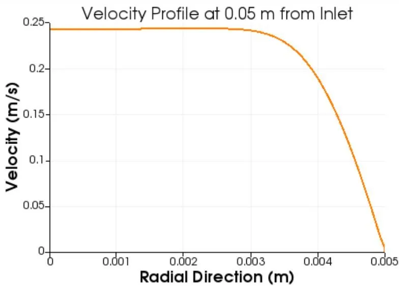
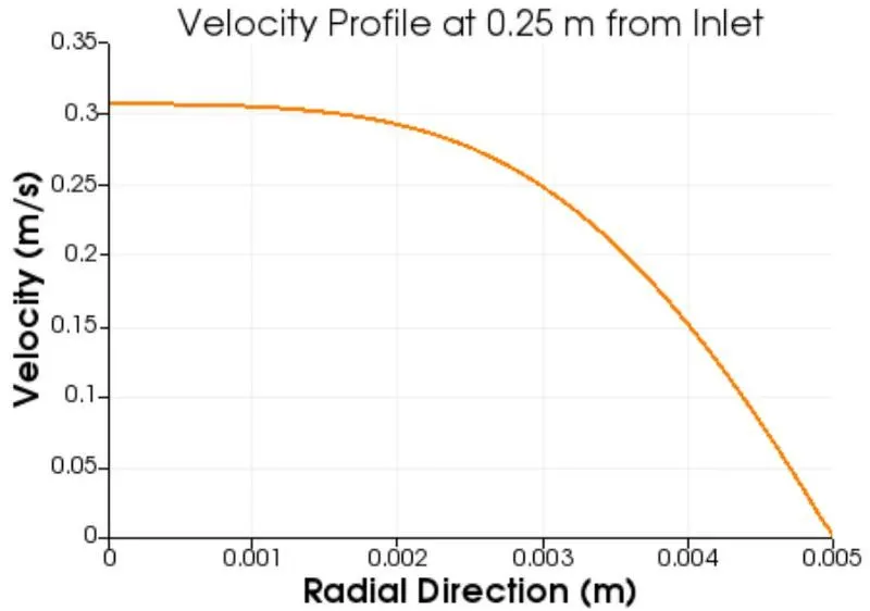
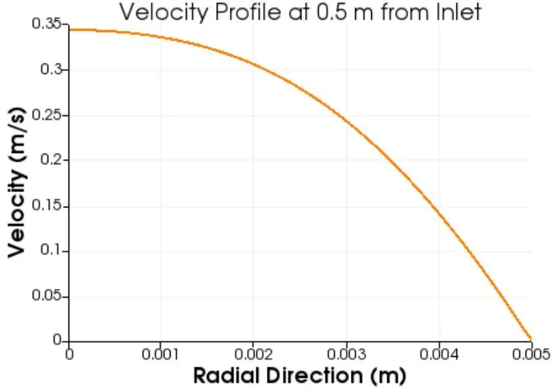
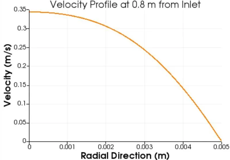
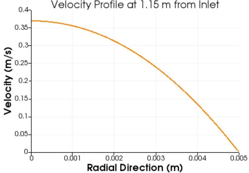
VELOCITY PROFILE:
SHEAR STRESS:
CONCLUSION:
- The velocity profiles changes until the flow is fully developed.
- The entry length for the flow is 1.2m After this distance from inlet, the velocity attains its characteristic parabola type shape and does not change any further.
- The velocity profile obtained is parabolic in nature with max velocity attained at the centre of the pipe.
- Shear Stress increases the friction on the walls of the pipe because of the which the velocity is maximum at the center of the pipe.
- The Shear stress plot is obtained after post processing and it is found that the shear stress is maximum at the walls and zero at the centre of the pipe.