Week 12:Project-1-Meshing of Door Inner Panel Challenge
Aim: To create the shell (2-D) meshing for the Car Side Door Panel by eliminating geometrical errors and considering the give element quality criteria using Hypermesh.
OBJECTIVE:
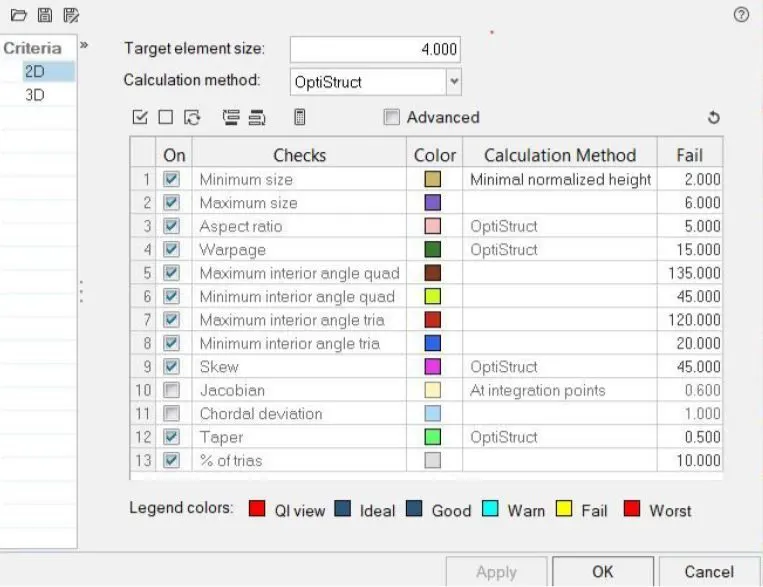
To Follow the Quality Criteria and mesh the following component and assign thickness:
Target Element Length = 4 Units
| S.N | Quality Criteria | Value |
| 1 | Aspect Ratio | 5 |
| 2 | Skewness | 45 |
| 3 | Warping | 15 |
| 4 | Taper | 0.5 |
| 5 | Min. Length | 2 Units |
| 6 | Max. Length | 6 Units |
| 7 | Min angle Quad | 45 |
| 8 | Max angle Quad | 135 |
| 9 | Min angle Tria | 20 |
| 10 | Max angle Tria | 120 |
| 10 | Tria % | 10 |
SOFTWARE USED :- Altair hyperworks 2021
THEORY:
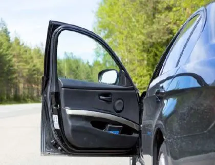
The door panel covers internal parts like the door handle, window switch, the power window motor, wiring, cup holder, audio speakers, storage compartment and other features. Mostly cars have door panels made from plastic most often using injection moulding, as well as incorporating other decorative materials. The door panel typically incorporates other parts that contribute to the appearance, functionality, and ergonomics of the vehicle. In most cases, the door panel is attached to the car's door frame by visible screws and ones hidden behind decorative plugs or under the armrest.
FINITE ELEMENT ANALYSIS:
The finite element method is a numerical technique for obtaining an approximate solution to a wide variety of engineering problems. FEA (Finite Element Analysis) is done by three phases.
1. Pre-processing
2. Solution
3. post-Processing
EXPLANATION:
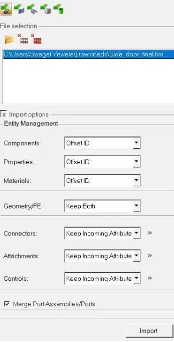
Import the given step file solver.
1. After that, assign quality parameters in Toolbar > preference > Criteria file setting > assign given quality parameters value > apply > OK.
2. Press the F to view the geometry on the origin.
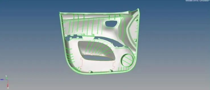
3. Extract mid-surface.
4. Defeature and proper connection of midle surface.
5. For capturing rib surface first remove all the fillets by using Defeature > Surface fillet > Select surface > Find > Remove option.
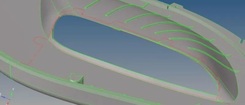
6. As one side of the surface is missing we can can easily offset from other surface so ther is no need to correct this geometry.
7. Visible only section 1 for extracting mid-surface and offset outer surface which contains less complicated surface like ribs, cylinder, dog house, etc.
8. First we need to measure the thickness of surface by creating one point and projecting same point on another surface and then switch on wireframe mode and measure the distance between two points by pressing F4 key.
9. Final view of mid-surface extracted.
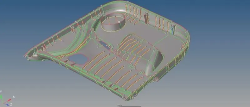
FINAL VIEW:
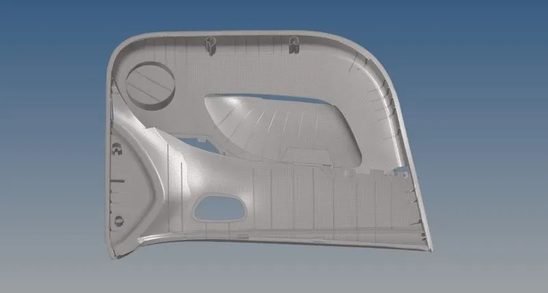
CONLUSION:
- Learned how to do manual midsurface to the component.
- Learned how to replace the unwanted surfaces manually.
- Learned how to cretae property thicknesses to different mm components.
- Learned how to translate the surfaces from one place to another.