Week 8 - Simulating Cyclone separator with Discrete Phase Modelling
Aim:
To perform analysis on cyclone separator and calculate the separation efficiency and pressure drop.
Case(i):
- To perform an analysis on a given cyclone separator model by varying the particle diameter from 1 μm to 5 μm and calculate the separation efficiency in each case. [Use both the velocity's as 3m/sec.]
Case(ii):
- To perform an analysis on a given cyclone separator model by varying the particle velocity from 1 m/sec to 5 m/sec and calculate the separation efficiency and pressure drop in each case. [Use particle diameter size as 5 μm for all cases & keep flow velocity same as particle velocity]
Description:
Cyclone Separator :
- Cyclone separators or simply cyclones are separation devices (dry scubbers) that use the principle of inertia to remove particulate matter from flue gases . Cyclone separators is one of many air pollution removers known as precleaners since they generally remove larger pieces of particulate matter.
- This prevents finer filtration methods from having to deal with large, more abrasive particles later on. In addition, several cyclone separators can operate in parallel, and this system is known as a multicyclone.
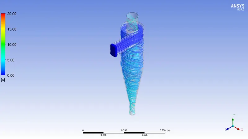
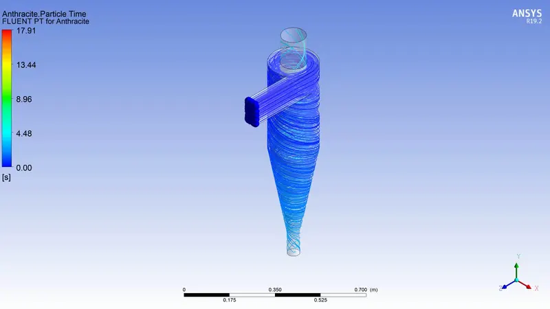
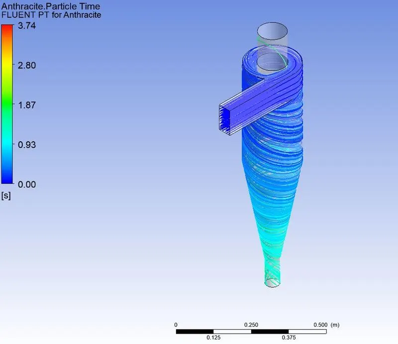
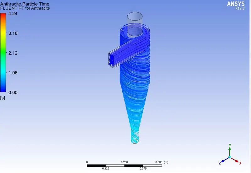
- Cyclone separators work much like a centrifuge, but with a continuous feed of dirty air. In a cyclone separator, dirty flue gas is fed into a chamber. The inside of the chamber creates a spiral vortex, similar to a tornado. This spiral formation and the separation is shown in Figure . The lighter components of this gas have less inertia, so it is easier for them to be influenced by the vortex and travel up it. Contrarily, larger components of particulate matter have more inertia and are not as easily influenced by the vortex.
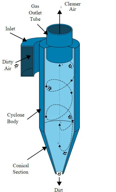
Four empirical models used to calculate the cyclone separator efficiency :
Iozia and Leith:
- Iozia and Leith (1990) logistic model is a modified version of Barth (1956) model which is developed based on force balance. The model assumes that a particle carried by the vortex endures the influence of two forces: a centrifugal force, Z, and a flow resistance, W. Core length, zc, and core diameter ,dc are given as:
`η ( i ) = 1 /( 1 + ((d ( p c ))/ (d ( p )) ) β`
`d(pc)= 50% cut size`
`d ( p c ) = (( 9 ⋅ μ ⋅ Q) /(π ⋅ ρ ( p ) ⋅ Z ( c ) ⋅ v 2 ) )^0.5`
Koch and Licht model:
- Koch and Licht inherently described the turbulent nature of cyclones and distribution of gas residence times within the cyclone. They attributed by the two following assumptions:
- The tangential velocity of the particle is equal to the tangential velocity of the gas flow. There is no slip in the tangential direction between gas nad particle.
- The tangential velocity is related to the radius of the cyclone by uR^n = constant
`η(i) = 1 -exp{-2 [(Gτ_i Q)/D63 (n+1) ]^(0.5/(n+1)) }`
Where,
`G =(8k_c)/((K_a^2 K_b^2))`
`n = 1-{1- (12D)^0.14/2.5}{T/530 +460/530}^0.3`
`τ_i=(ρ_p d_pi^2)/(18μ)`
Li and Wand model:
- The Li and Wand model includes particle bounce or re-entrainment and turbulent diffusion at the cyclone wall. A two-dimensional analytical expression of particle distribution in the cyclone is obtained. Li and Wang's model was developed based on the following assumptions:
- The radial particle velocity and the radial concentration profile are not constant for uncollected particles within the cyclone.
- Boundary conditions with the consideration of turbulent diffusion coefficient and particle bounce re-entrainment on the cyclone wall are
`c = c_0, at θ=0`
`D_r ((∂c)/(∂r))=(1-α)wc,at r=D/2`
Lapple Model:
- Lapple model was developed based on force balance without considering the flow resistance. Lapple assumed that a particle entering the cyclone is evenly distributed across the inlet opening. The particle that travels from inlet half-width to the wall in the cyclone is collected with 50% efficiency. The semi-empirical relationship developed by Lapple to calculate a 50% cut diameter, `d_pc`is
`d_pc=[9μb/((2πN_e v_i (ρ_p-ρ_g ) ))]^(1/2)`
Where Ne is the number of revolution
`N_e=1/a [h+(H-h)/2]`
The efficiency of collection of any size of the particle is,
`η_i=1/(1+((d_(pc))/d_pi )^2 )`
Analysis Procedure:
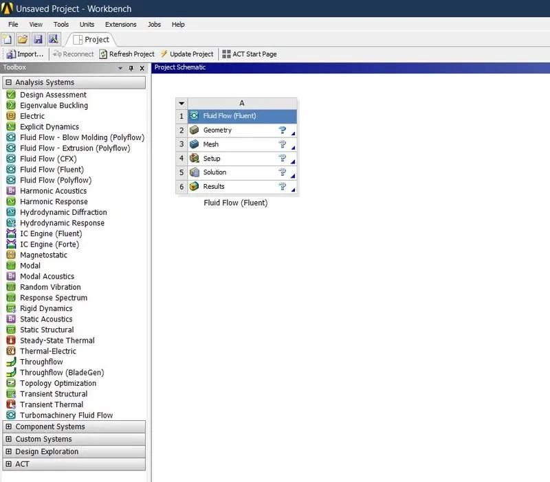
- Open Ansys workbench and drag the Fluid Flow(Fluent) to main window.
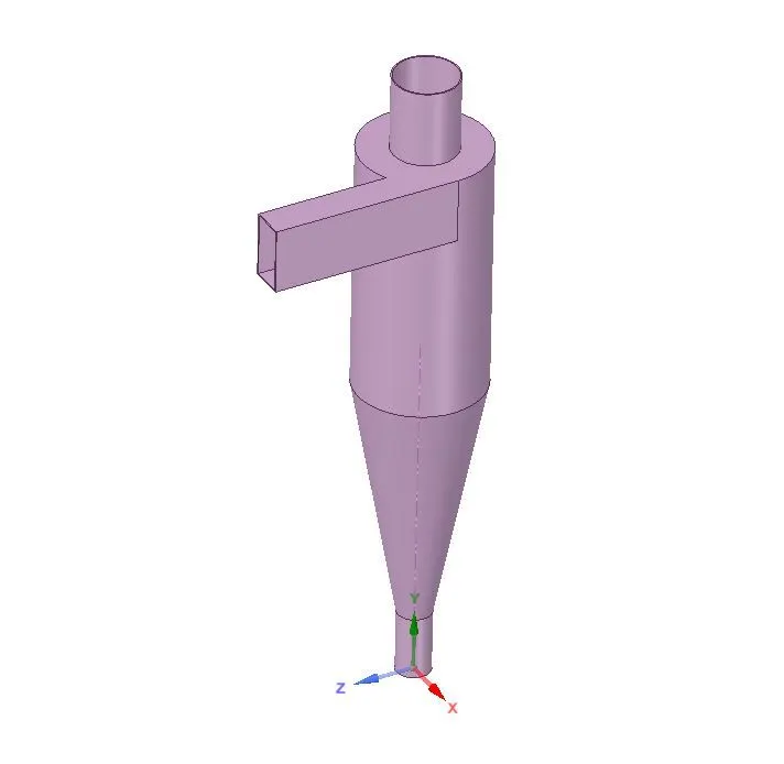
- Go to geometry to import the geometry file.
- Select the edges of the surface which the fluid flow takes place by using Volume Ectract option in geometry window.
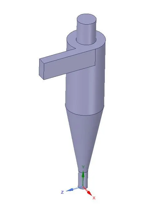
- Then update geometry in main window. After that go to mesh.
- Select the faces by using selecting face option then name the faces like “Inlet, Outlet 1,outer 2”.
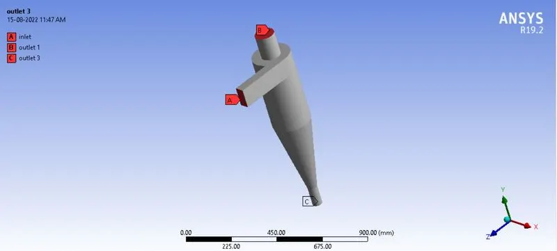
- Then select mesh enter the appropriate mesh size after that generate the mesh. Then update the mesh in main window.
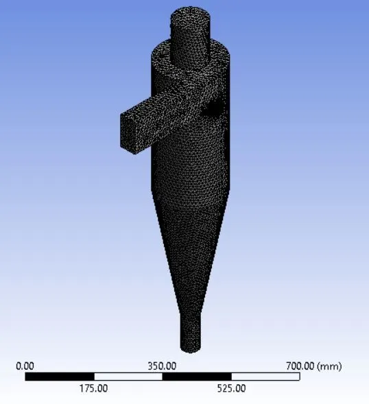
- Go to the setup to setting up the solver to analys the cyclone separator.
- Select the steady state- pressure based- k-epsilon -RNG solver to solve.
- Then go to Discrete phase modeling select injector as Anthracite with required diameter and velocity at the inlet.
- Then go to boundary condition enter the velocity and select the DPM and select the appropriate Discrete phase BC type such as
- Inlet and wall - Reflect
- Outlet 1- Escape
- Outlet 2 - Trap
- Then go to solving select standard solution and initialize the solution from inlet and then enter the iteration number. After that run the simulation.
Results:
Case(i)
1) particle diameter = 1μm
Velocity = 3m/sec
Residual:
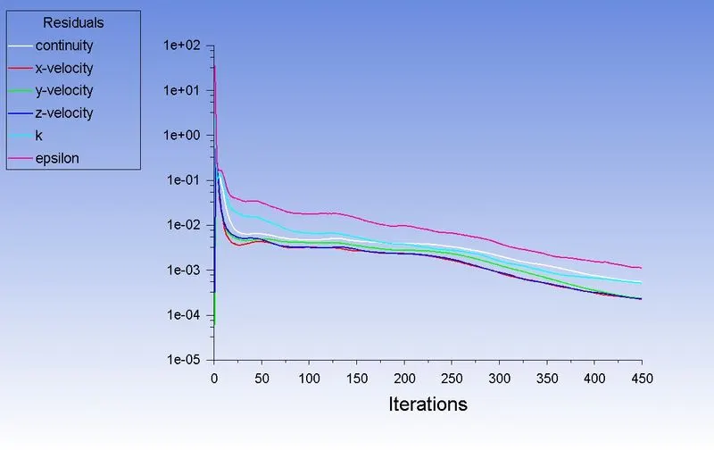
Flow:
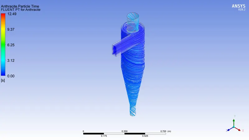
Animation:
https://drive.google.com/file/d/102RblRAZxFbElmp6UDNbporYpeSgqxF-/view?usp=sharing
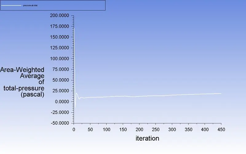
Pressure at inlet:
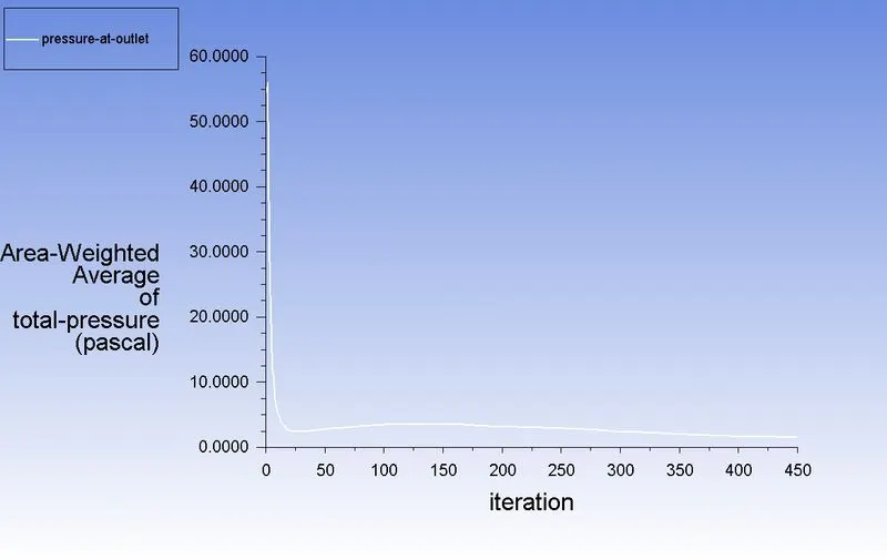
Pressure at outlet:
Pressure drop:
Pressure drop = Total inlet pressure - Total Outlet Pressure
= 171.86-54.49
Pressure drop = 117.37 pa
Efficiency:
Separation efficiency = (number of particles trapped/number of particles tracked )*100
number of particles tracked =124
number of particles trapped =29
So, separation efficiency = (29/124)*100 = 23.38%
2) particle diameter = 2μm
Velocity = 3m/sec
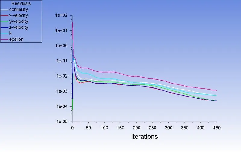
Residual:
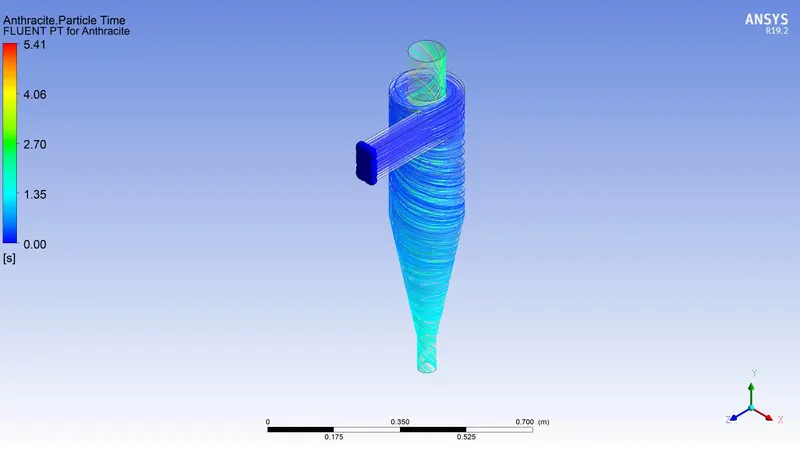
Flow:
Animation:
https://drive.google.com/file/d/102RblRAZxFbElmp6UDNbporYpeSgqxF-/view?usp=sharing
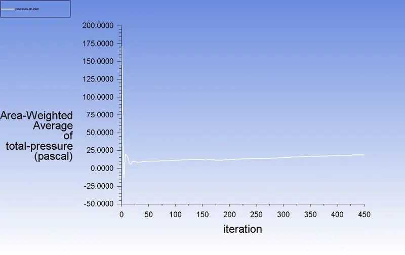
Pressure at inlet:
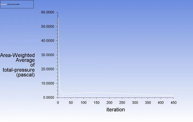
Pressure at outlet:
Pressure drop:
Pressure drop = Total inlet pressure - Total Outlet Pressure
= 171.86-54.49
Pressure drop = 117.37 pa
Efficiency:
Separation efficiency = (number of particles trapped/number of particles tracked )*100
number of particles tracked =124
number of particles trapped =88
So, separation efficiency = (88/124)*100 = 70.96%
3) particle diameter = 3μm
Velocity = 3m/sec
Residual:
Flow:
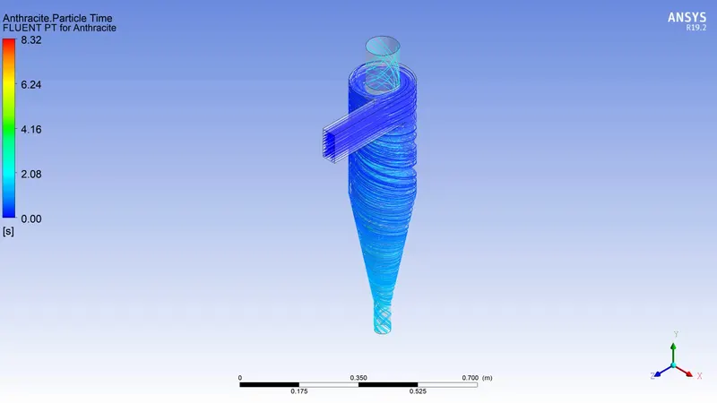
Animation:
https://drive.google.com/file/d/1O4d6k5s4t4NyWc-F26FKDutkpXhLNPcE/view?usp=sharing
Pressure at inlet:
Pressure at outlet:
Pressure drop:
Pressure drop = Total inlet pressure - Total Outlet Pressure
= 171.86-54.49
Pressure drop = 117.37 pa
Efficiency:
Separation efficiency = (number of particles trapped/number of particles tracked )*100
number of particles tracked =124
number of particles trapped =98
So, separation efficiency = (98/124)*100 = 79.83%
4) particle diameter = 4μm
Velocity = 3m/sec
Residual:
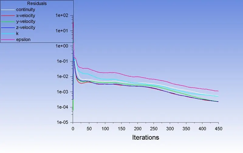
Flow:
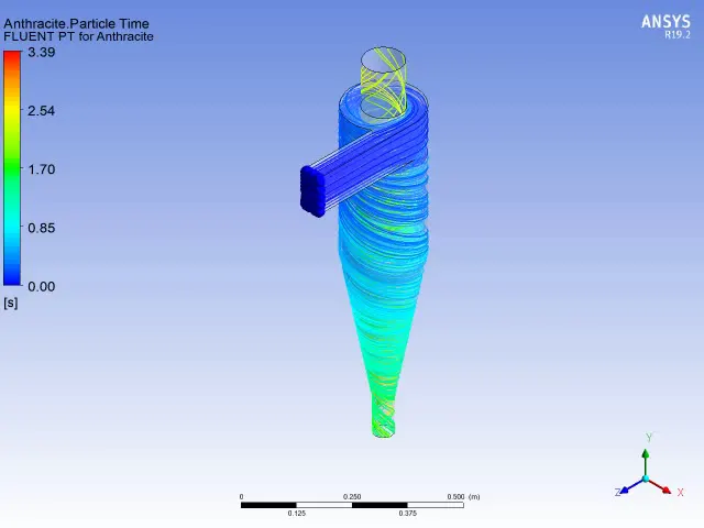
Animation:
https://drive.google.com/file/d/1hxgpRw7M4C6QTiRJ289Be9vvcYJgr4fM/view?usp=sharing
Pressure at inlet:
Pressure at outlet:
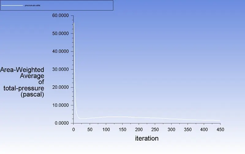
Pressure drop:
Pressure drop = Total inlet pressure - Total Outlet Pressure
= 171.86-54.49
Pressure drop = 117.37 pa
Efficiency:
Separation efficiency = (number of particles trapped/number of particles tracked )*100
number of particles tracked =124
number of particles trapped =109
So, separation efficiency = (109/124)*100 = 87.90%
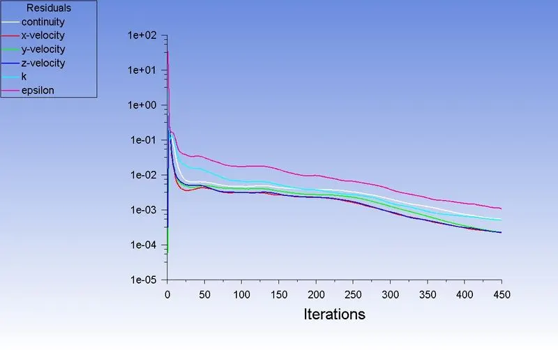
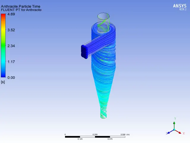
5) particle diameter = 5μm
Velocity = 3m/sec
Residual:
Flow:
Animation:
https://drive.google.com/file/d/16Cmw5qCfj28i09Wqnv6S-ZfBk1Ex1sY0/view?usp=sharing
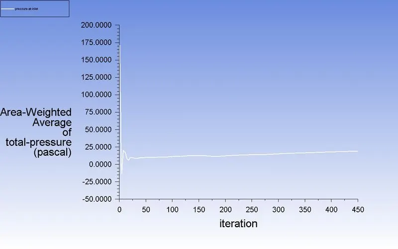
Pressure at inlet:
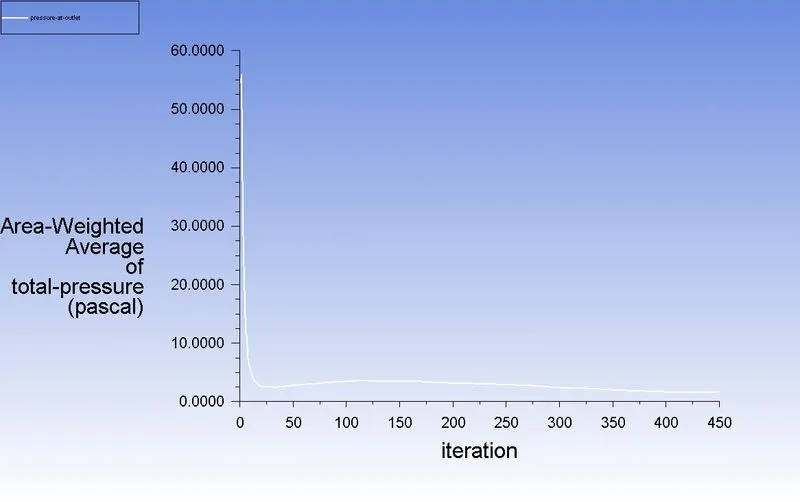
Pressure at outlet:
Pressure drop:
Pressure drop = Total inlet pressure - Total Outlet Pressure
= 171.86-54.49
Pressure drop = 117.37 pa
Efficiency:
Separation efficiency = (number of particles trapped/number of particles tracked )*100
number of particles tracked =124
number of particles trapped =115
So, separation efficiency = (115/124)*100 = 92.74%
| Diameter (μm) | Velocity (m/sec) | Particle Tracked | Particle Trapped | Separator Efficiency (%) | Pressure Drop(pa) |
| 1 | 3 | 124 | 29 | 23.38 | 117.37 |
| 2 | 3 | 124 | 88 | 70.96 | 117.37 |
| 3 | 3 | 124 | 98 | 79.83 | 117.37 |
| 4 | 3 | 124 | 109 | 87.90 | 117.37 |
| 5 | 3 | 124 | 115 | 92.74 | 117.37 |
Case(ii)
1) particle diameter = 5μm
Velocity = 1m/sec
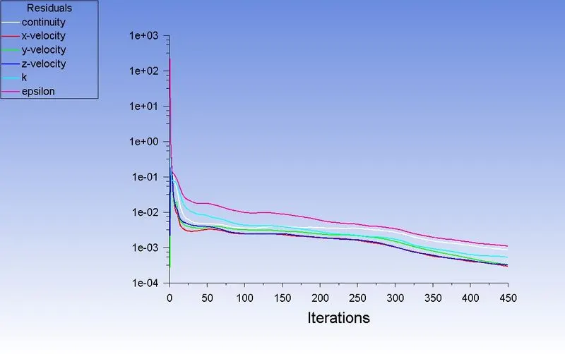
Residual:
Flow:
Animation:
https://drive.google.com/file/d/14a3De9oyJHfnOp-bw9FTMr4ziA93Cpwp/view?usp=sharing
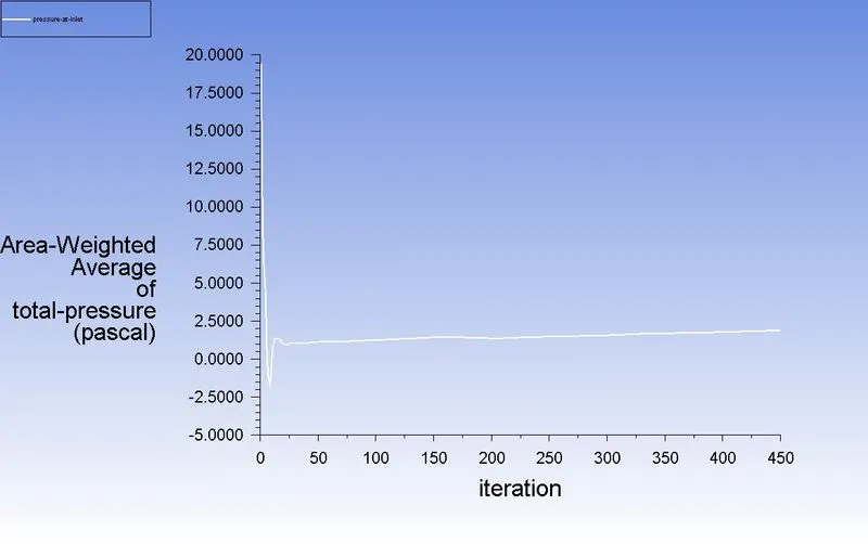
Pressure at inlet:
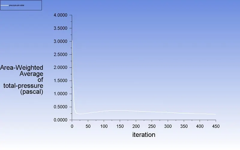
Pressure at outlet:
Pressure drop:
Pressure drop = Total inlet pressure - Total Outlet Pressure
= 19.47-3.03
Pressure drop = 16.44 pa
Efficiency:
Separation efficiency = (number of particles trapped/number of particles tracked )*100
number of particles tracked =124
number of particles trapped =9
So, separation efficiency = (9/124)*100 = 7.25%
2) particle diameter = 5μm
Velocity = 2m/sec
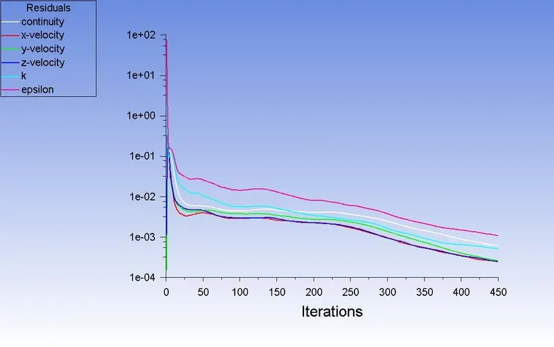
Residual:
Flow:
Animation:
https://drive.google.com/file/d/1YKjpsNT9dNg5aDeNt2p_i9dvjSW5ILdv/view?usp=sharing
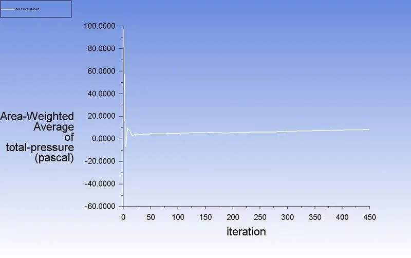
Pressure at inlet:
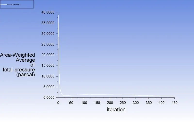
Pressure at outlet:
Pressure drop:
Pressure drop = Total inlet pressure - Total Outlet Pressure
= 97.61-38.77
Pressure drop = 58.84 pa
Efficiency:
Separation efficiency = (number of particles trapped/number of particles tracked )*100
number of particles tracked =124
number of particles trapped =16
So, separation efficiency = (16/124)*100 = 12.90%
3) particle diameter = 5μm
Velocity = 3m/sec
Residual:
Flow:
Animation:
https://drive.google.com/file/d/1PLuggty8RE3Dz0DXUj7YpGUppLr8uBS3/view?usp=sharing
Pressure at inlet:
Pressure at outlet:
Pressure drop:
Pressure drop = Total inlet pressure - Total Outlet Pressure
= 171.86-54.49
Pressure drop = 117.37 pa
Efficiency:
Separation efficiency = (number of particles trapped/number of particles tracked )*100
number of particles tracked =124
number of particles trapped =115
So, separation efficiency = (115/124)*100 = 92.74%
4) particle diameter = 5μm
Velocity = 4m/sec
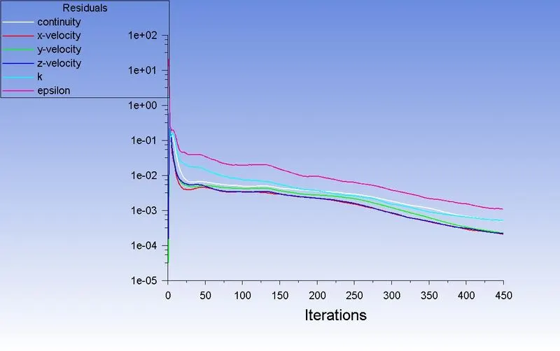
Residual:
Flow:
Animation:
https://drive.google.com/file/d/1UyxYMge6jYKchq11lFqojJtnQW4ZqfRm/view?usp=sharing
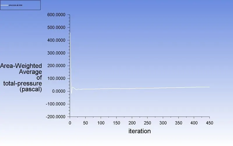
Pressure at inlet:
Pressure at outlet:
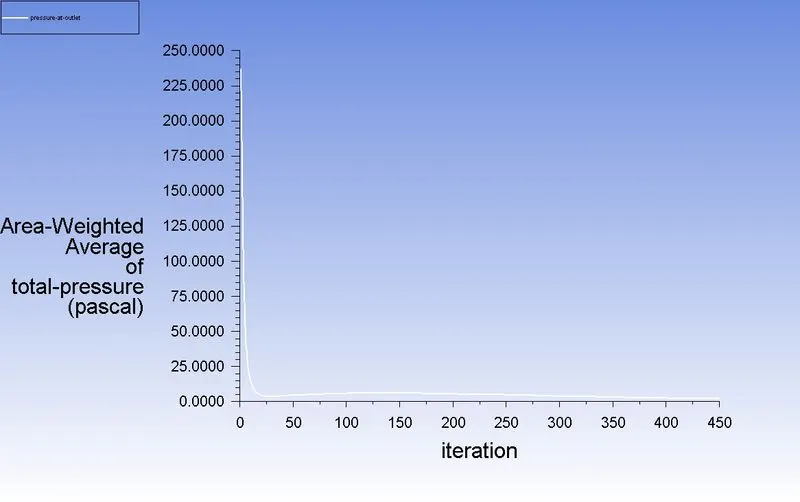
Pressure drop:
Pressure drop = Total inlet pressure - Total Outlet Pressure
= 460.91-237.61
Pressure drop = 223.30 pa
Efficiency:
Separation efficiency = (number of particles trapped/number of particles tracked )*100
number of particles tracked =124
number of particles trapped =119
So, separation efficiency = (119/124)*100 = 95.96%
5) particle diameter = 5μm
Velocity = 5m/sec
Residual:
Flow:
Animation:
https://drive.google.com/file/d/1hxgpRw7M4C6QTiRJ289Be9vvcYJgr4fM/view?usp=sharing
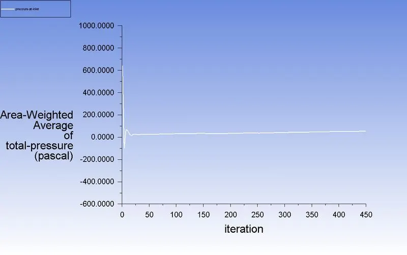
Pressure at inlet:
Pressure at outlet:
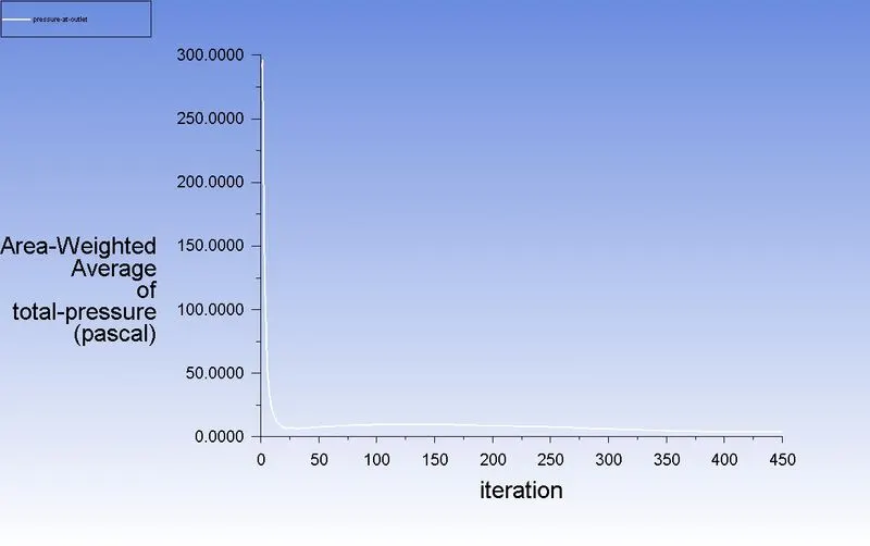
Pressure drop:
Pressure drop = Total inlet pressure - Total Outlet Pressure
= 645.65-289.99
Pressure drop = 355.66 pa
Efficiency:
Separation efficiency = (number of particles trapped/number of particles tracked )*100
number of particles tracked =124
number of particles trapped =123
So, separation efficiency = (123/124)*100 = 99.19%
| Diameter (μm) | Velocity (m) | Particle Tracked | Particle Trapped | Separator Efficiency (%) | Pressure Drop(pa) |
| 5 | 1 | 124 | 9 | 7.25 | 16.44 |
| 5 | 2 | 124 | 16 | 12.90 | 58.84 |
| 5 | 3 | 124 | 115 | 92.74 | 117.37 |
| 5 | 4 | 124 | 119 | 95.96 | 223.30 |
| 5 | 5 | 124 | 123 | 99.19 | 355.66 |