Week 9 - Parametric study on Gate valve.
Aim:
- To perform a parametric study on the gate valve simulation by setting the opening from 10 % to 80%.
Description:
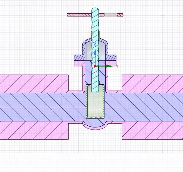
- Gate valves work by inserting a rectangular gate or wedge into the path of a flowing fluid. They are operated by a threaded stem which connects the actuator (generally a hand wheel or motor) to the stem of the gate. If the valve has a rising stem its position can be seen just by looking at the position of the stem. A gate valve is used to control the fluid flow through lifting and descending the gate. A gate distinct feature is to provide an unobstructed passageway, which includes minimal pressure loss over the valve.
- When the gate is fully opened there is no restriction to the flow hence the pressure drop is low comparatively. Generally, the gate valve are fully closed or fully open as partially opened valve may experience vibration which may lead to excessive wear. A gate valve's main component is body, seat, gate, stem, bonnet, and actuator. the primary mechanism is straight forward where the handwheel is rotated to move the gate up and down via threads. they require more than a 360-degree turn to fully open the valve.
- Gate valves tend to be slightly cheaper than ball valves of the same size and quality. They are slower in actuation than quarter-turn valves and are for applications where valve operation is infrequent, such as isolating valves. Gate valves should be used either fully open or fully closed, not to regulate flow. Automated gate valves exist with either an electric or pneumatic actuator, but a manual gate valve is cost-effective since they have infrequent usage. Gate valves are widely used for all types of applications and are suitable for both above-ground and underground installation. They are suitable for most fluids including steam, water, oil, and gas, etc.
simulation Procedure:
- Open ansys drag ansys fluent to the main window.
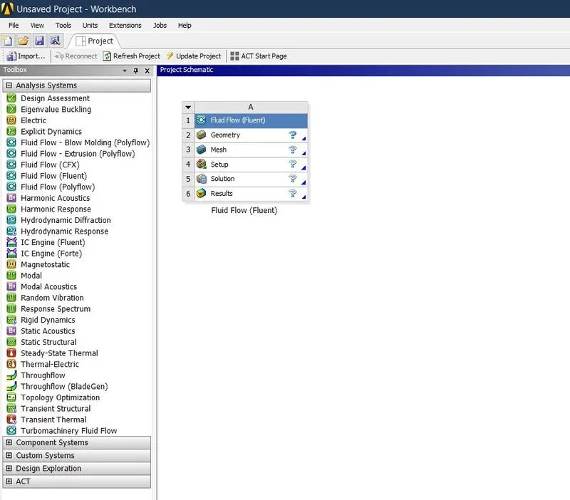
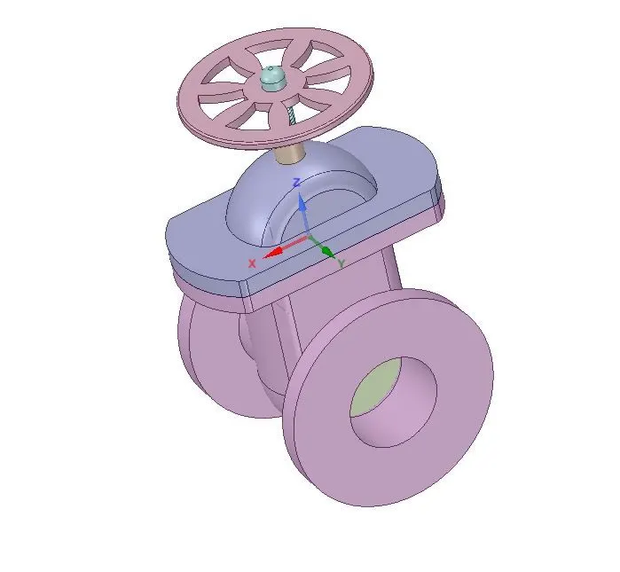
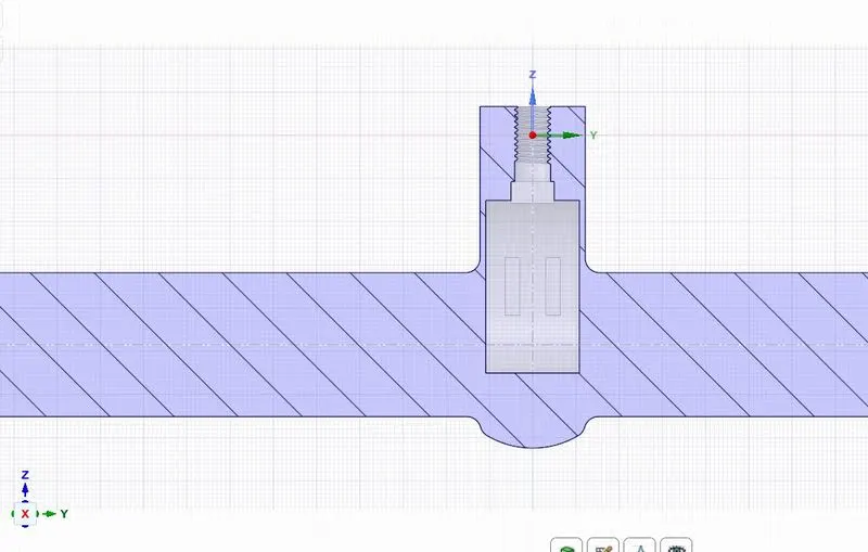
- Go to geometry to import the Gate valve geometry.
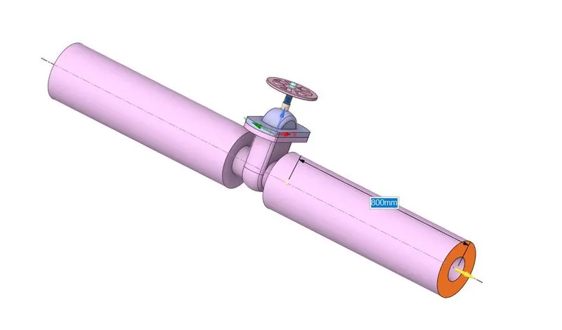
- Pull the inlet and outlet of gatebalve.
- Move the disc to appropriate distance enable the parametric option for future progress.
- Use volume extract option to ectract the fluid flow volume by selecting the edges fluid flow.
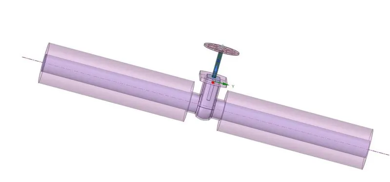
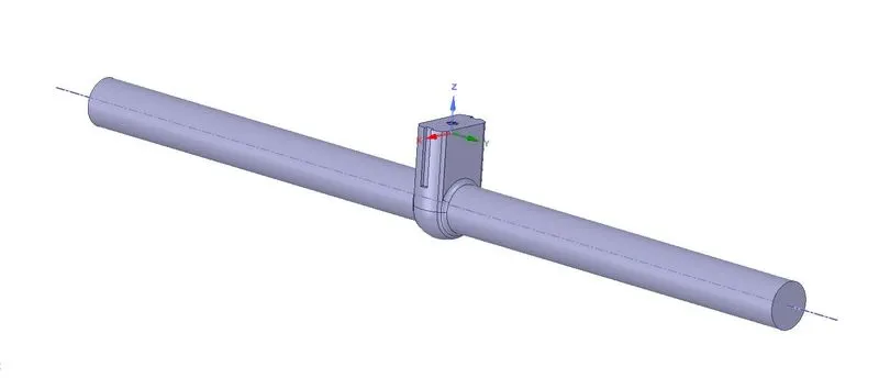
- Update the geometry in main window then go to mesh. Enter appropriate mesh size.
- Select the faces and named as 'inlet' and 'outlet'.
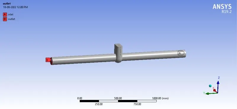
- Then generate the mesh.
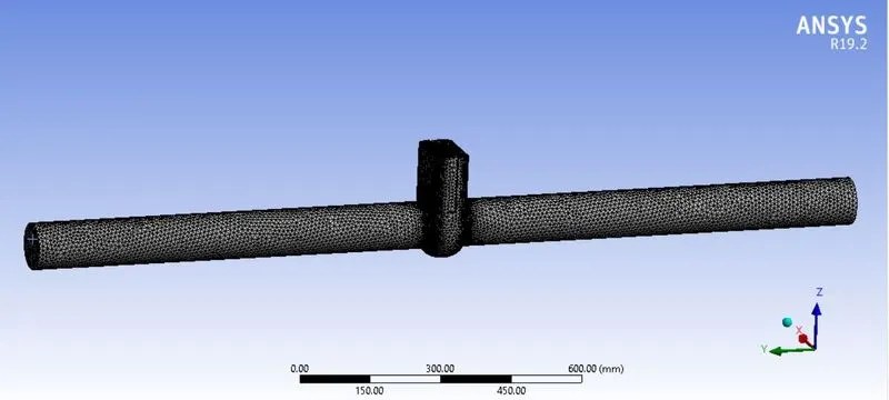
- Update the mesh in the main window. Then go to setup to setting up the solver,vicous model and the boundary conditions.
- Set standard method and initialize the solution from inlet. After that create required contours. Then enter the no. of iteration and run the calcuation.
Outputs:
Mass flow rate at different disc displacements:

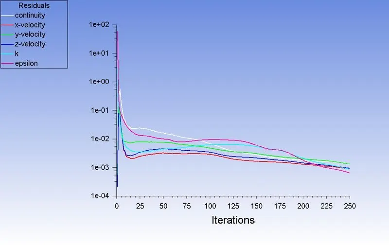
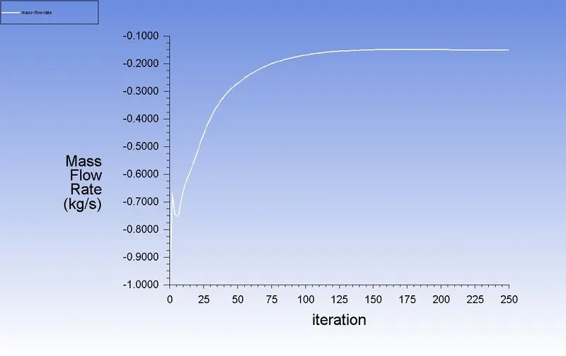
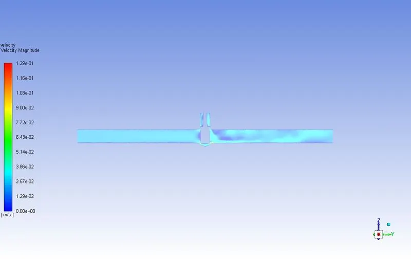
Gate disc lift = 10mm
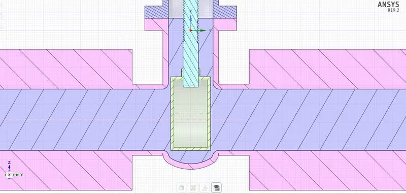
Residual:
Mass flow rate:
Velocity:
Flow Coefficient & Flow Factor:
`Cv = Q√(SG)/(∇P)`
Q =0.14918
SG = 1000/998.2 = 1
∇P = 10 psi
`Cv =0.14918*√1/10`
`Cv =0.14918 *0.31622`
Cv =0.04717
`Kv = 0.865*Cv`
`Kv = 0.865*0.04717`
Kv =0.04080
Gate disc lift = 20mm
Residual:
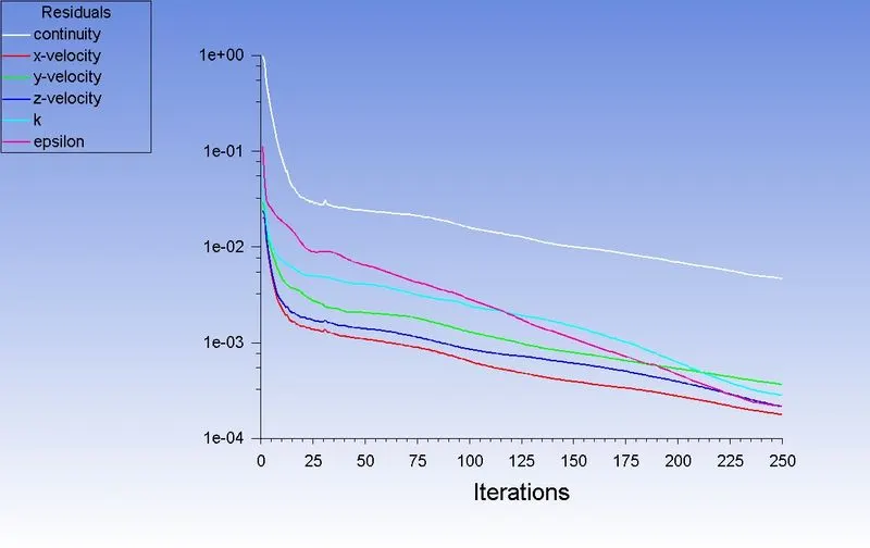
Mass flow rate:
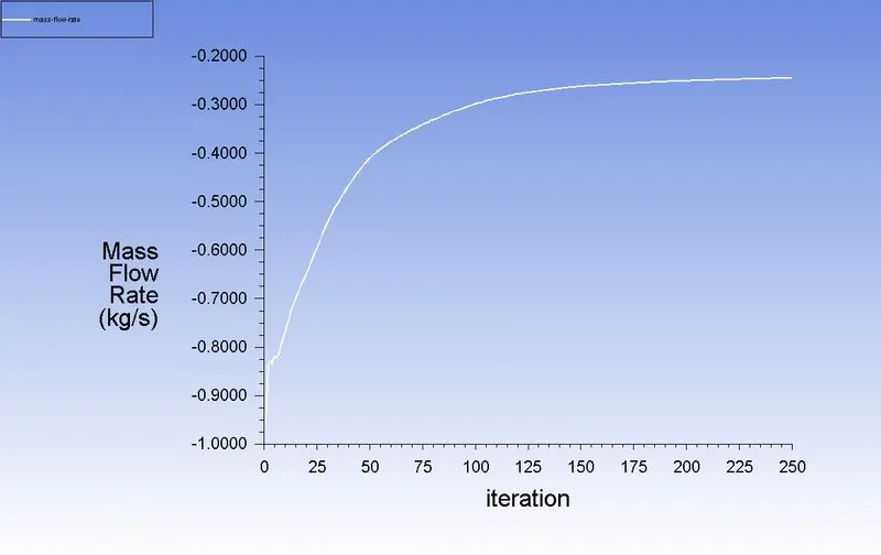
Velocity:
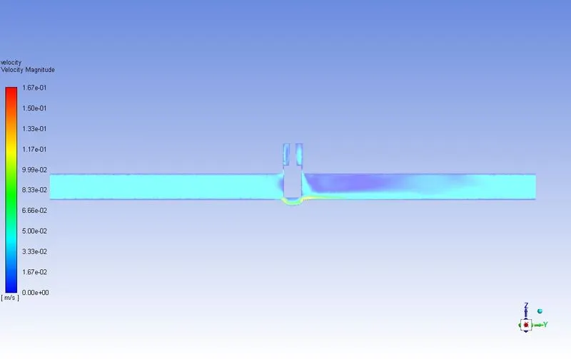
Flow Coefficient & Flow Factor:
`Cv = Q√(SG)/(∇P)`
Q =0.23891
SG = 1000/998.2 = 1
∇P = 10 psi
`Cv = 0.23891*√1/10`
`Cv =0.23891 *0.31622`
Cv =0.07554
`Kv = 0.865*Cv`
`Kv = 0.865*0.07554`
Kv =0.06534
Gate disc lift = 30mm
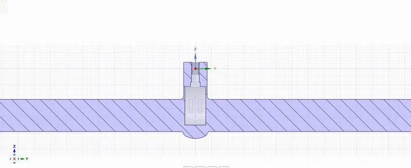
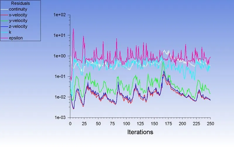
Residual:
Mass flow rate:
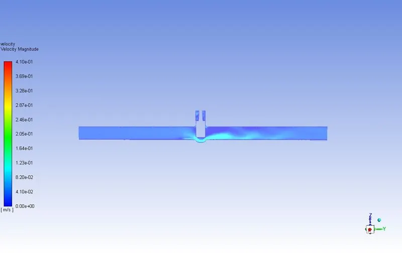
Velocity:
Flow Coefficient & Flow Factor:
`Cv = Q√(SG)/(∇P)`
Q =0.35891
SG = 1000/998.2 = 1
∇P = 10 psi
`Cv =0.35891 *√1/10`
`Cv = 0.35891*0.31622`
Cv =0.11349
`Kv = 0.865*Cv`
`Kv = 0.865*0.11349`
Kv =0.09817
Gate disc lift = 40mm
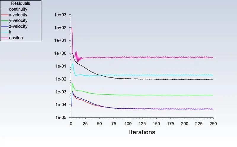
Residual:
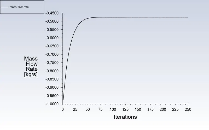
Mass flow rate:
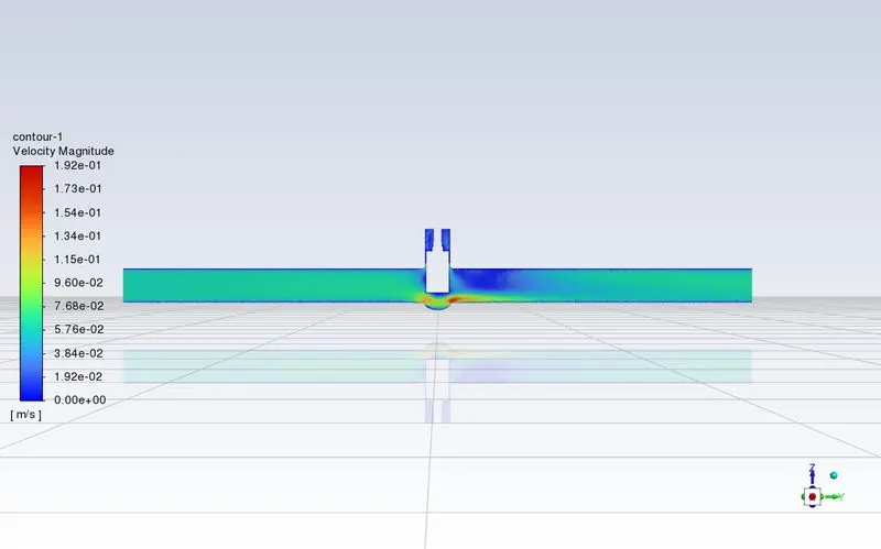
Velocity:
Flow Coefficient & Flow Factor:
`Cv = Q√(SG)/(∇P)`
Q =0.47541
SG = 1000/998.2 = 1
∇P = 10 psi
`Cv = 0.47541*√1/10`
`Cv = 0.47541*0.31622`
Cv =0.15033
`Kv = 0.865*Cv`
`Kv = 0.865*0.15033`
Kv =0.13000
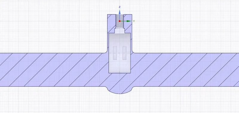
Gate disc lift = 50mm
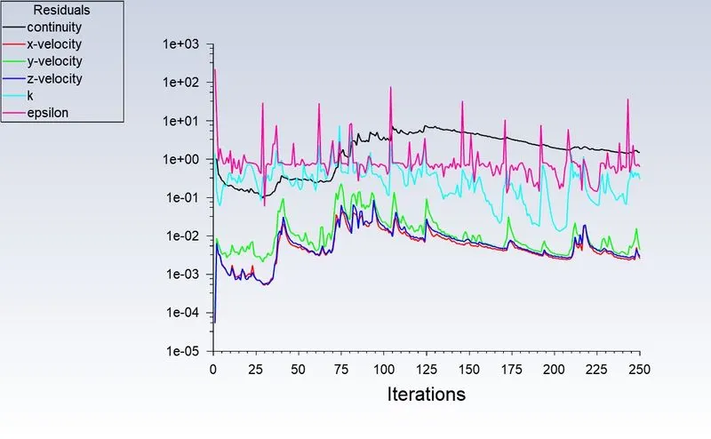
Residual:
Mass flow rate:
Velocity:
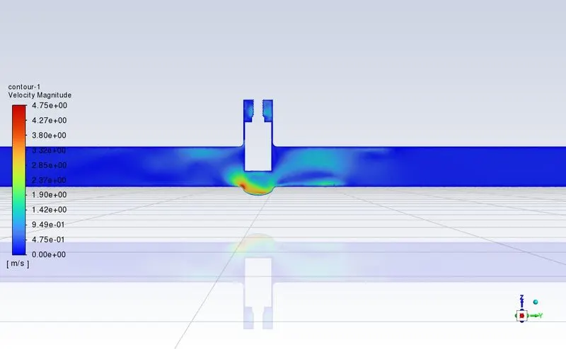
Flow Coefficient & Flow Factor:
`Cv = Q√(SG)/(∇P)`
Q =0.32412
SG = 1000/998.2 = 1
∇P = 10 psi
`Cv = 0.32412*√1/10`
`Cv = 0.32412*0.31622`
Cv =0.10249
`Kv = 0.865*Cv`
`Kv = 0.865*0.10249`
Kv =0.08865
Gate disc lift = 60mm
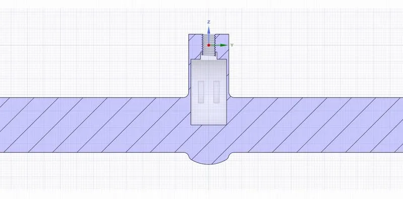
Residual:
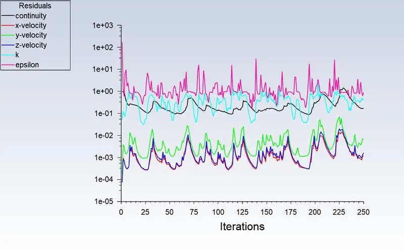
Mass flow rate:
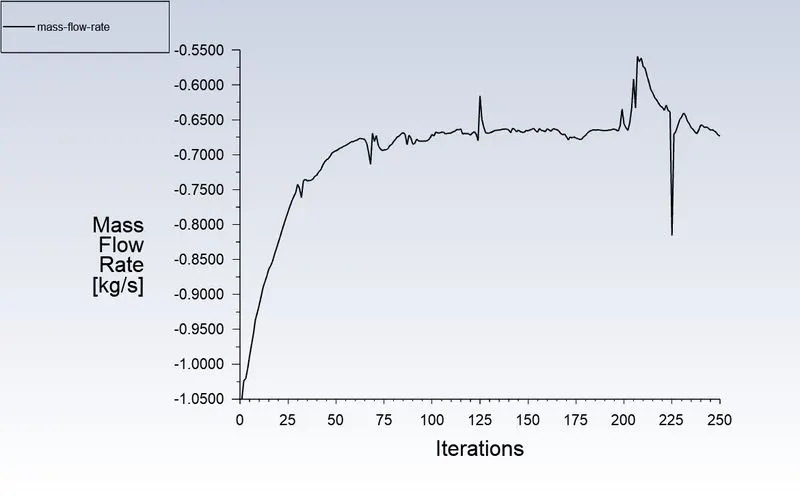
Velocity:
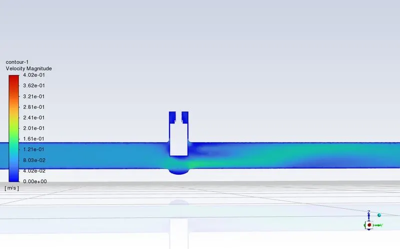
Flow Coefficient & Flow Factor:
`Cv = Q√(SG)/(∇P)`
Q =0.67343
SG = 1000/998.2 = 1
∇P = 10 psi
`Cv =0.67343 *√1/10`
`Cv = 0.67343*0.31622`
Cv =0.21295
`Kv = 0.865*Cv`
`Kv = 0.865*0.21295`
Kv =0.18420
Gate disc lift = 70mm
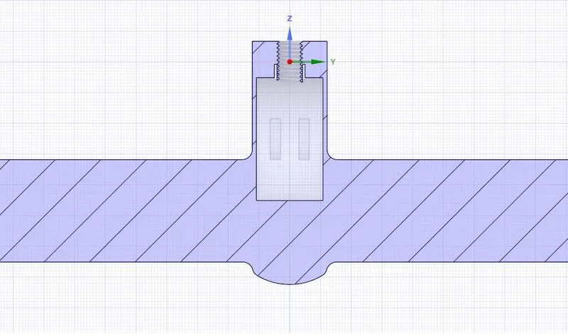
Residual:
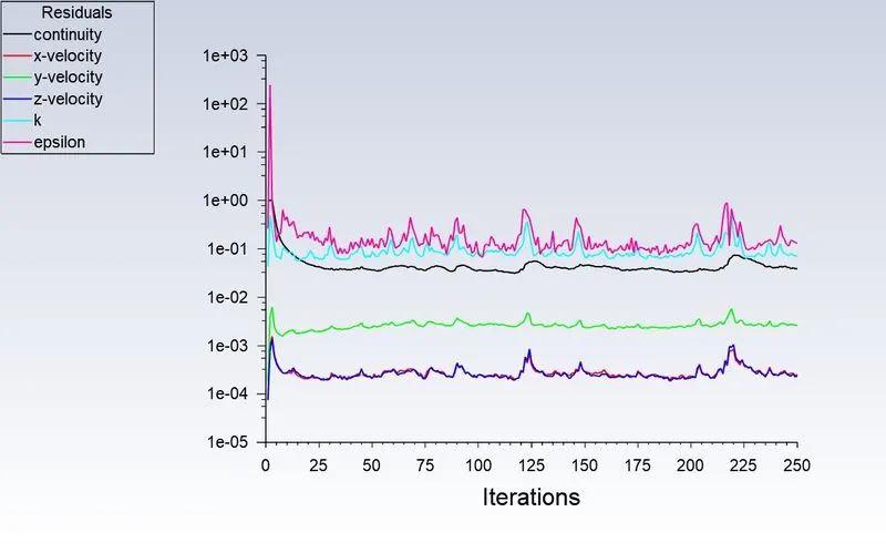
Mass flow rate:
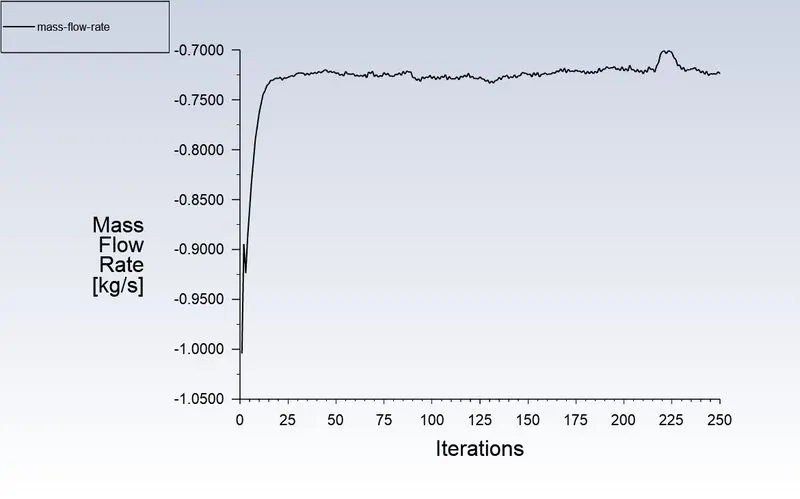
Velocity:
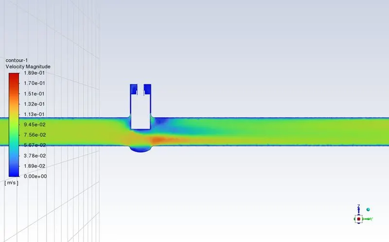
Flow Coefficient & Flow Factor:
`Cv = Q√(SG)/(∇P)`
Q =0.72382
SG = 1000/998.2 = 1
∇P = 10 psi
`Cv = 0.72382*√1/10`
`Cv = 0.72382*0.31622`
Cv =0.22888
`Kv = 0.865*Cv`
`Kv = 0.865*0.22888`
Kv =0.19798
Gate disc lift = 80mm
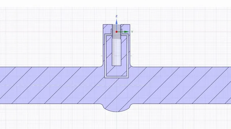
Residual:
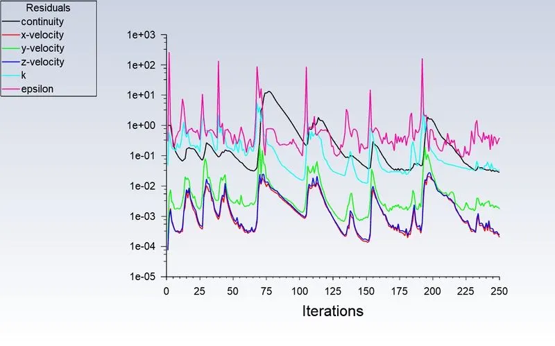
Mass flow rate:
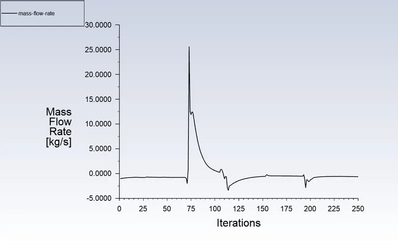
Velocity:
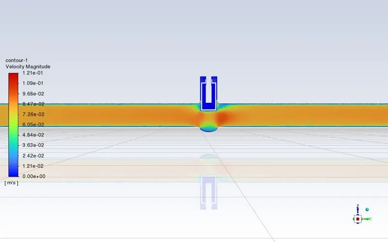
Flow Coefficient & Flow Factor:
`Cv = Q√(SG)/(∇P)`
Q =0.62257
SG = 1000/998.2 = 1
∇P = 10 psi
`Cv =0.62257 *√1/10`
`Cv = 0.62257*0.31622`
Cv =0.19686
`Kv = 0.865*Cv`
`Kv = 0.865*0.19686`
Kv =0.17029