Week 1: Channel flow simulation using CONVERGE CFD
Aim:
To perform a channel flow simulation using Converge-CFD and post process the results in Paraview.
Objective:
Run a simulation for three times with different mesh size and compare the results. Three different base mesh sizes are,
- dx = 2e-4m, dy = 2e-4m, dz = 2e-4m
- dx = 1.5e-4m, dy = 1.5e-4m, dz = 1.5e-4m
- dx = 1e-4m, dy = 1e-4m, dz = 1e-4m
Procdure:
- Open Converge studio and create a geometry of a Channel. For this go to geometry -> Create-> Shape-Box-> Specify the centre of geometry.
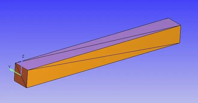
- Then go to Geometry-> Options-> Slect surface normal. After seleting the Surface normal the normal pits towards outside, select any one arrow that is point outward and click on them, then the normls change their direction to inwards.
- After that diagnosis the geometry to identify the any errors/problems. If there are no error found then the geometry is correct.
- Then the case setup mustbe done. Go to case setup, give required input that needed for each option in the setup one by one to run a simuation.
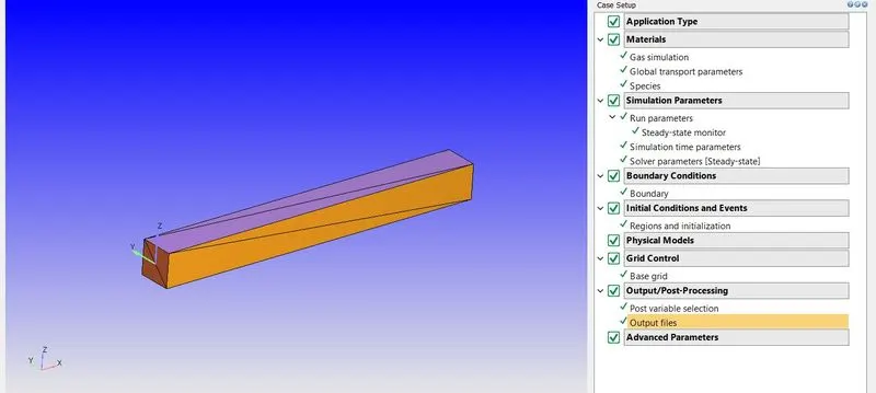
Case Setup:
Application Type = Time Based
Materials:
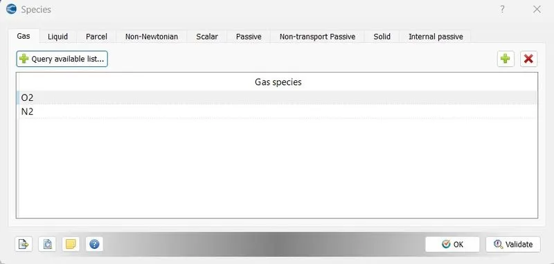
Predefined mixture = Air
Species:
Simulation Parameters:
Run Parameters:
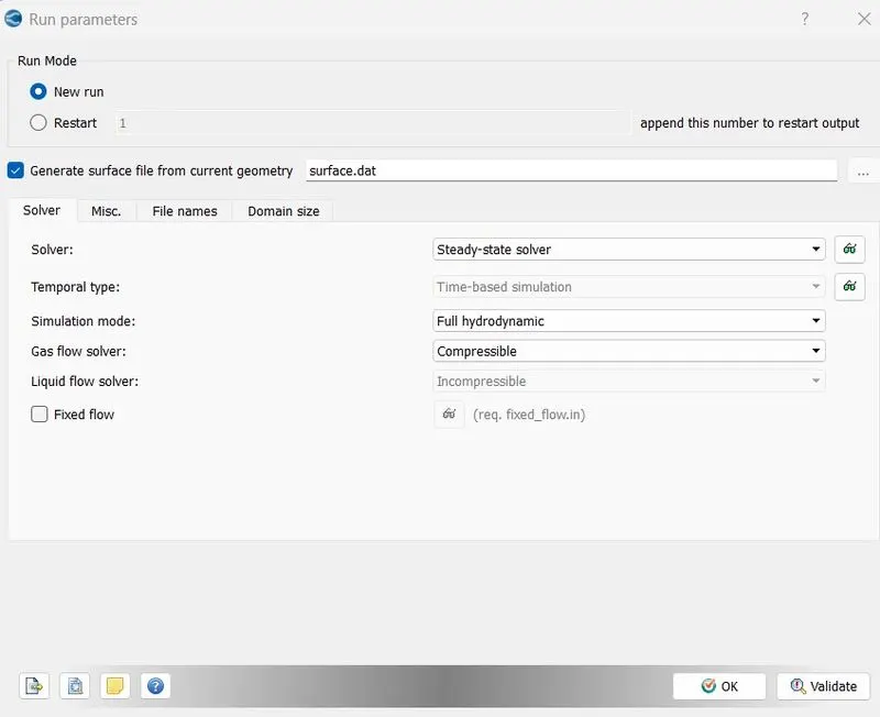
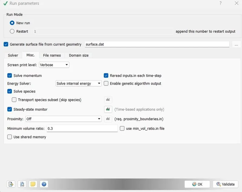
Steady- State Monitor:
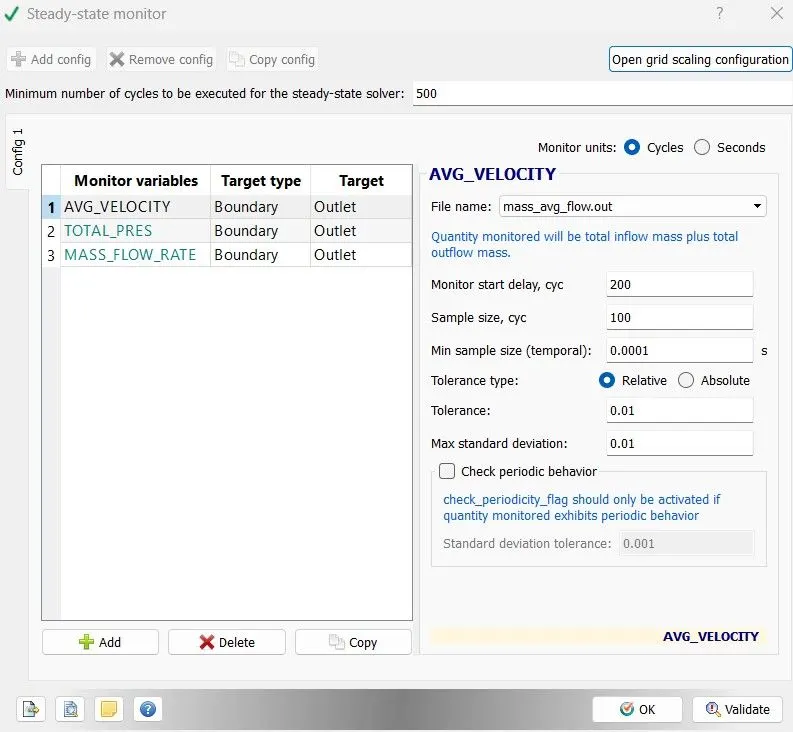
Simulation Time Parameter:
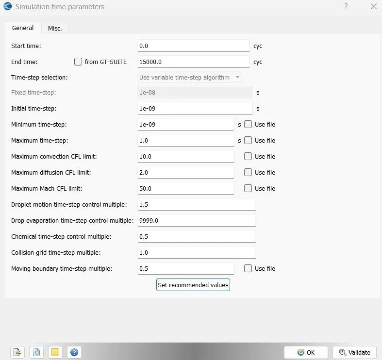
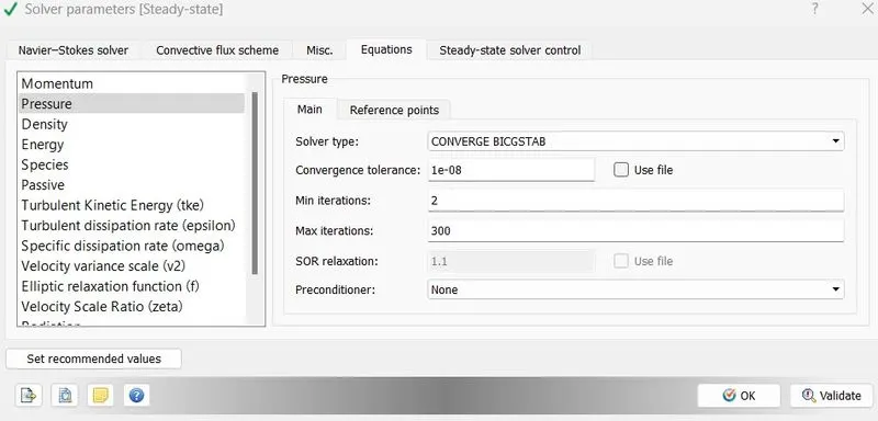
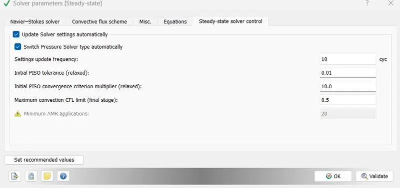
Solver Parameters [Steady state]:
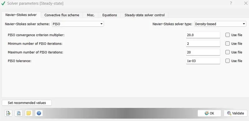
Boundary Conditions:
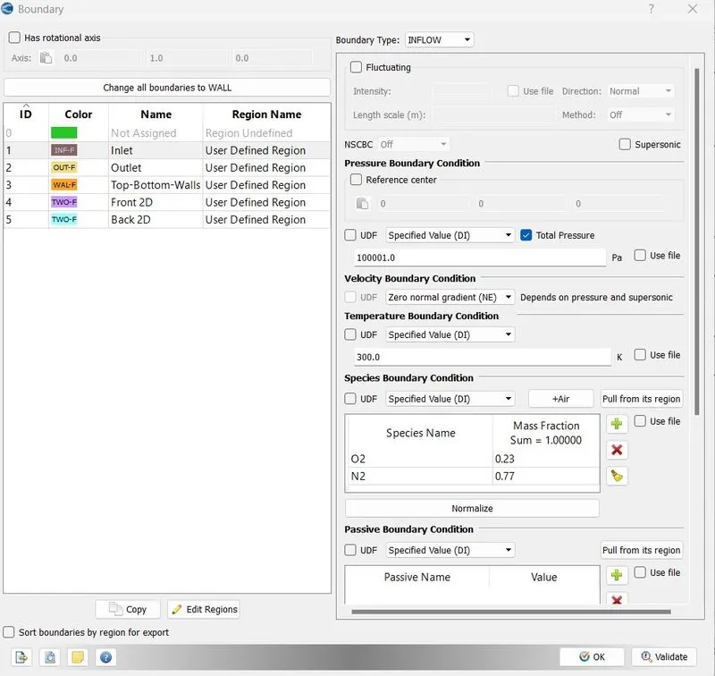
Inlet:(INFLOW)
Outlet:(OUTFLOW)

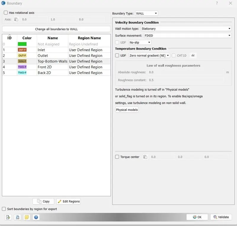
Walls:(WALL)
Front &Back: (TWO_D)
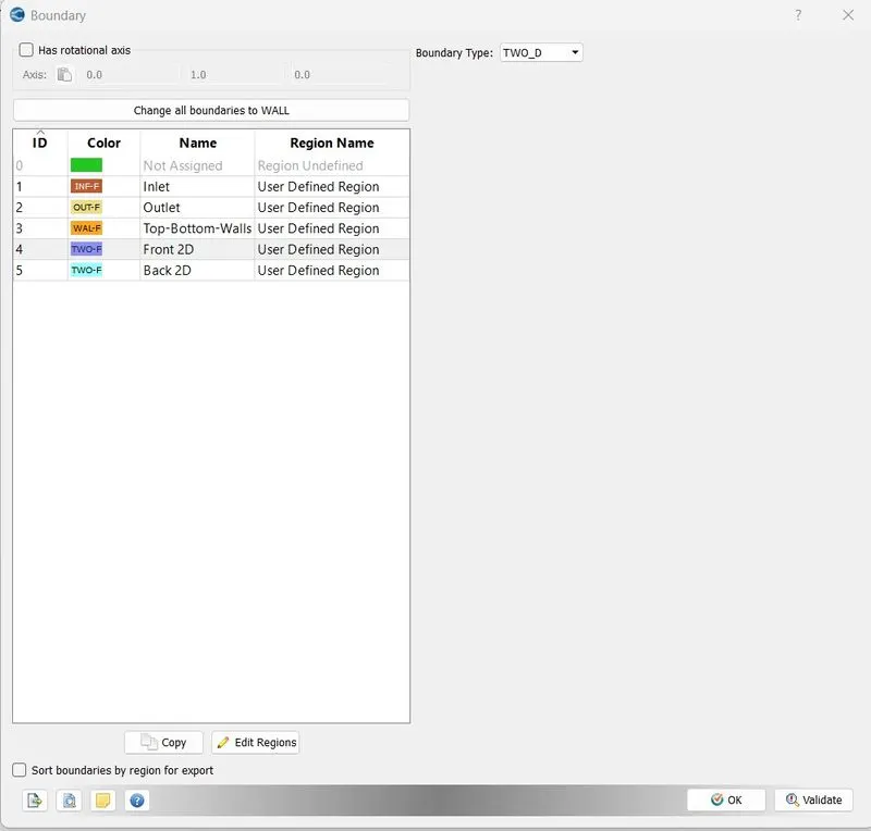
Regions:
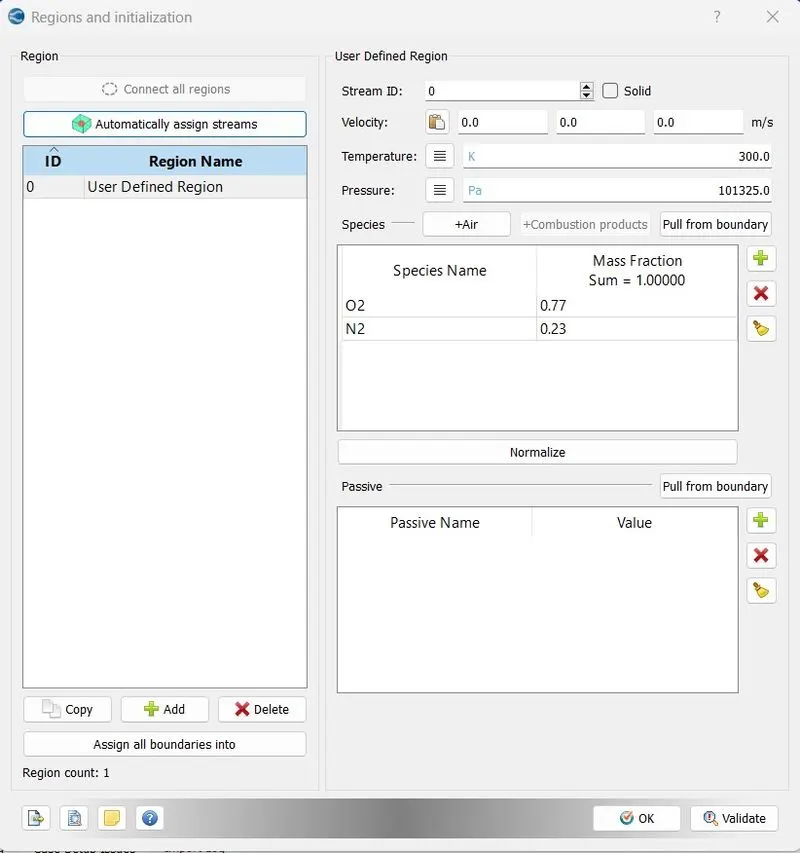
Physical Models:
Uncheck the turbulence modelling in this case.
Grid Control:
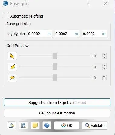
Change the dx, dy and dz value for different mesh size simulation.
For case-1 dx = 2e-4m, dy = 2e-4m, dz = 2e-4m
case-2 dx = 1.5e-4m, dy = 1.5e-4m, dz = 1.5e-4m
case-3 dx = 1e-4m, dy = 1e-4m, dz = 1e-4m
Post Processing:
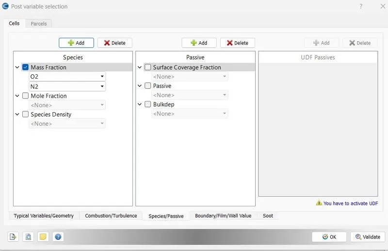
Output files:
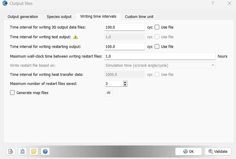
- After setting up the case export all the input files for futher procedure.
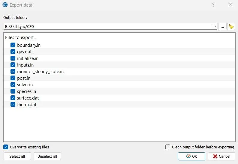
- Then open Cygwin and navigate to the location where the input files are exported earlier.
- After navigate to the respective folder, Run a simu;ation by using specific commands "mpiexec.exe -n 4 converge.exe restricted logfile &"
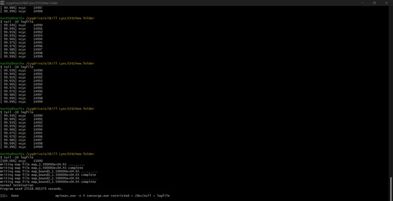
- It will take some time to run a simulation, once the simulation is completed it will create multiple output data files.
- Those output files need to be converts in the format that can access in Paraview, so convert all output files in the format of paraview VTK in-line binary format.
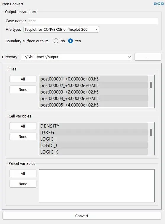
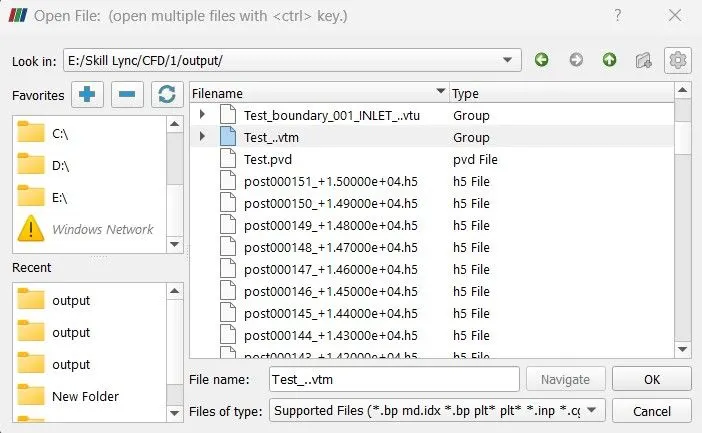
- After that open Paraviem and import the converted files in Paraview interface. And then slice the geometry to get 2D plots then run the simulation in paraview.
- Plots can be generated by using line plotting option, hence required plots, contours and animation can obtained in paraview.
- And we can generate the plots in Converge Studio also.
- Repeat the same procedure for different mesh size simulation.
Results:
case-1
Mesh size - dx = 2e-4m, dy = 2e-4m, dz = 2e-4m
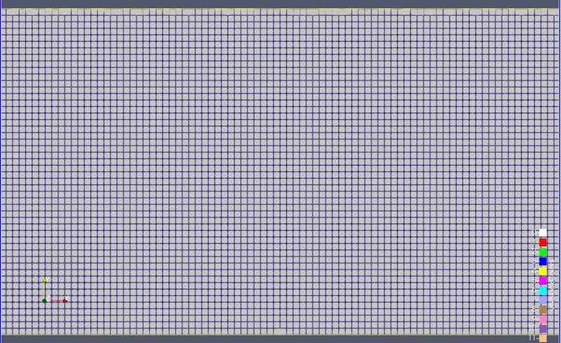
Velocity Contour:
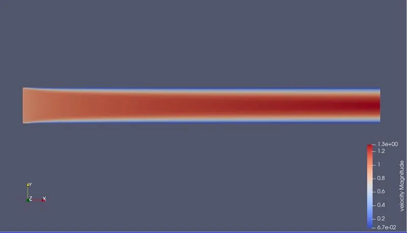
Pressure Contour:
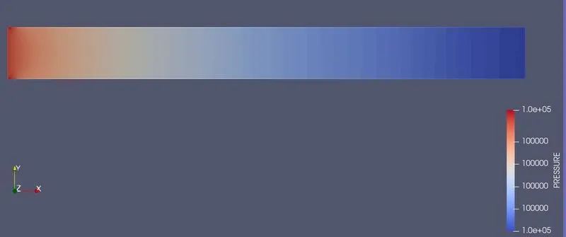
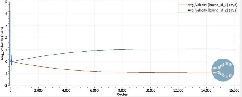
Velocity Plot:
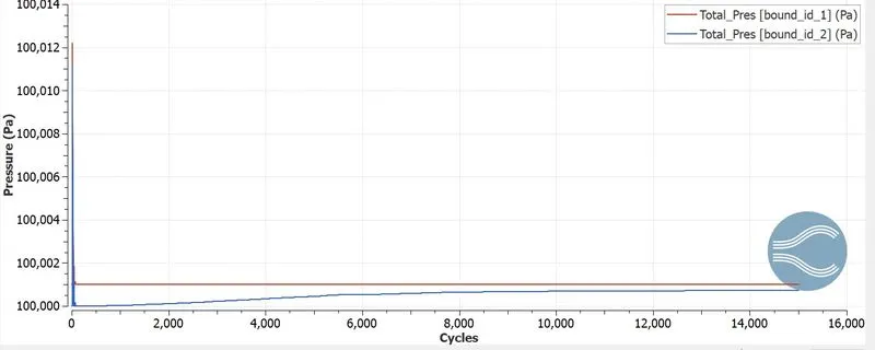
Pressure Plot:
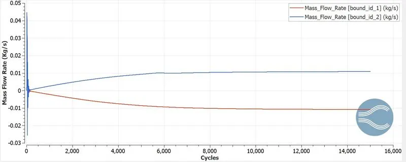
Mass Flow Rate Plot:
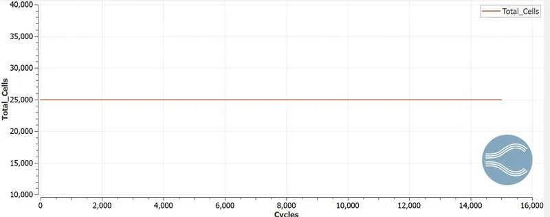
Total Cell Counts:
Animation:
Velocity:
Pressure:
Case-2
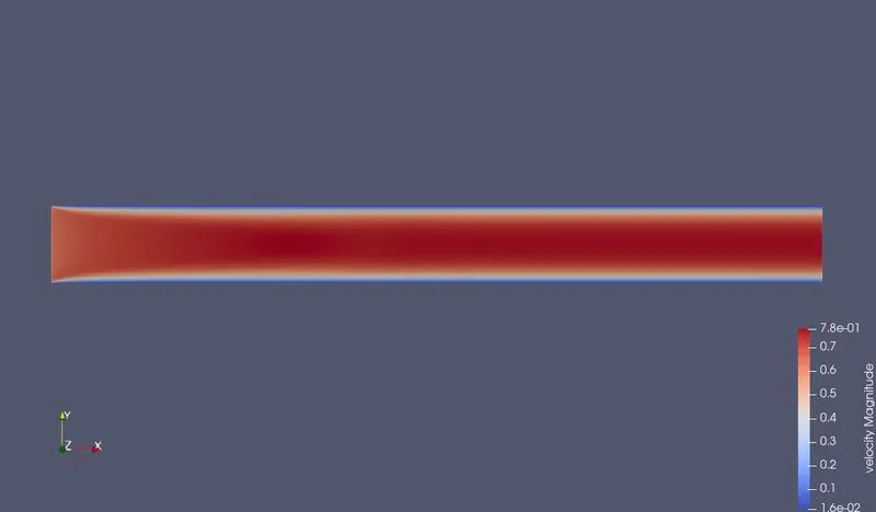
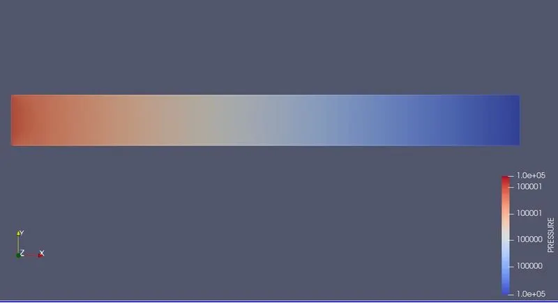
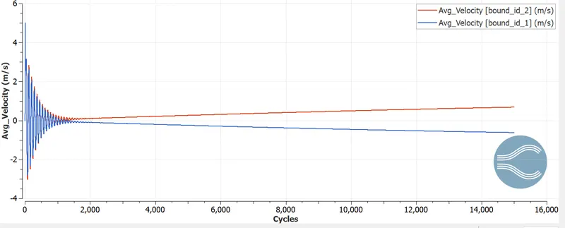
Mesh size - dx = 1.5e-4m, dy = 1.5e-4m, dz = 1.5e-4m
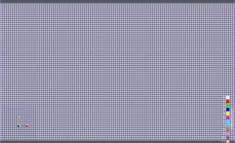
Velocity Contour:
Pressure Contour:
Velocity Plot:
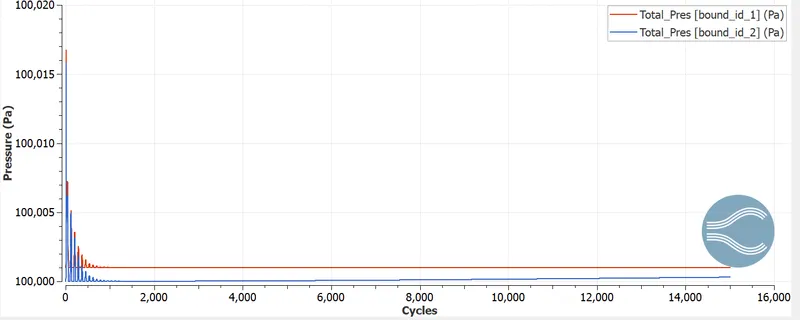
Pressure Plot:
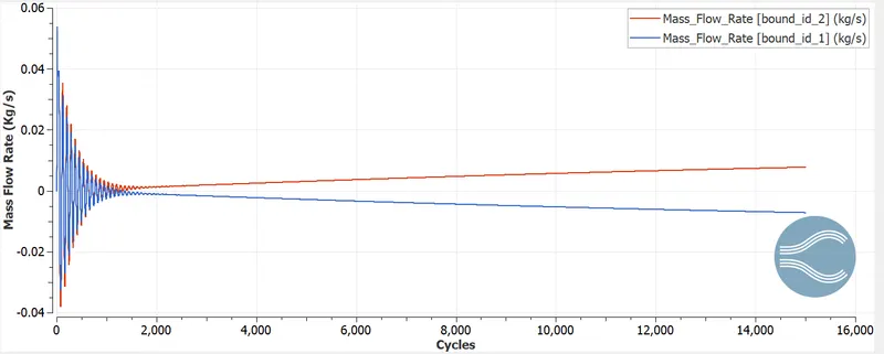
Mass Flow Rate Plot:
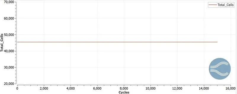
Total Cell Counts:
Animation:
Velocity:
Pressure:
case-3
Mesh size - dx = 1e-4m, dy = 1e-4m, dz = 1e-4m
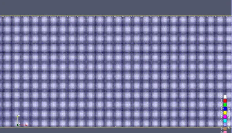
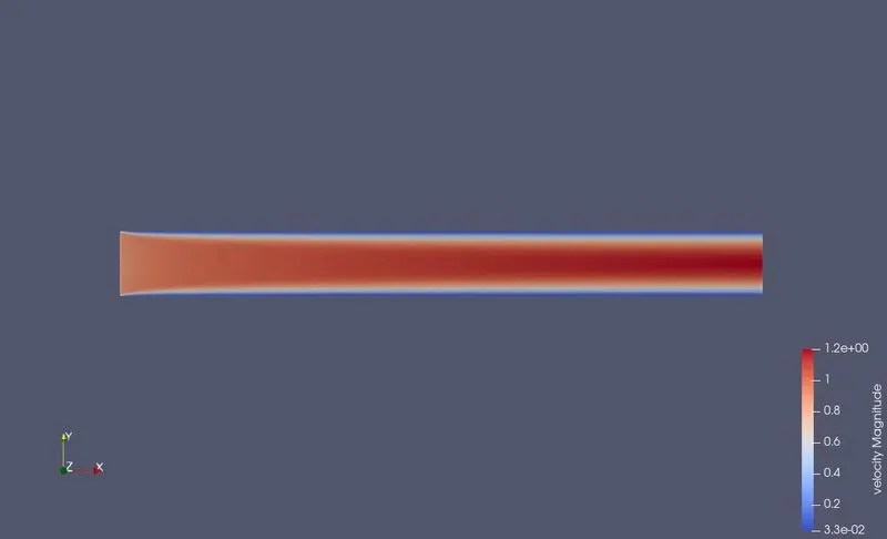
Velocity Contour:
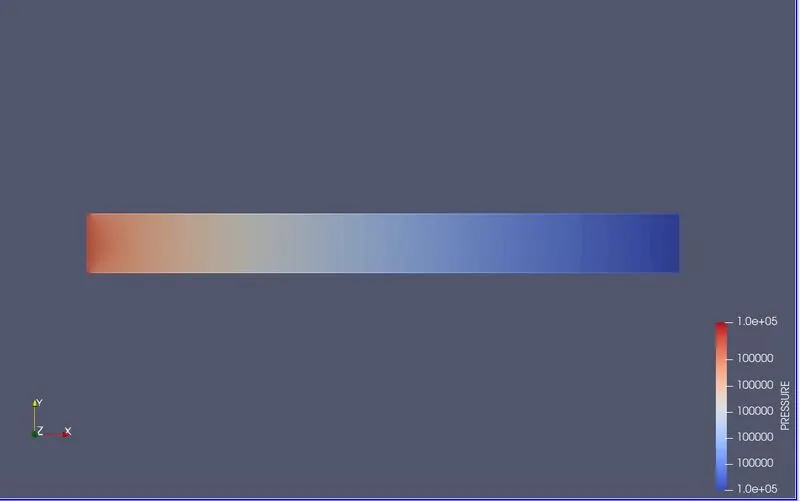
Pressure Contour:
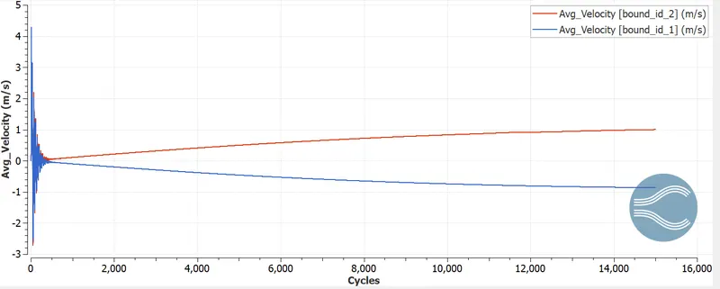
Velocity Plot:
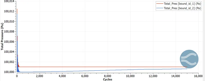
Pressure Plot:
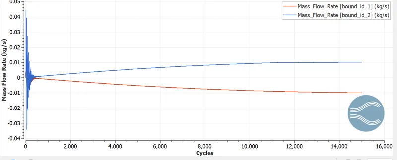
Mass Flow Rate Plot:
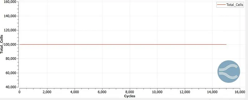
Total Cell Counts:
Animation:
Velocity:
Pressure:
Observation:
- The results shws that the number of total cell counts for mesh size 2e-4m, 1.5e-4m and 1e-4m are 25000,45500 and 100000 respectively. Hence as the mesh becomes more finer and finer the total cell count increases, as the cell count increases the computational time also increases.
- The pressure obtained in all the cases remains constant. This is because both inlet and outlet are provided with constrained boundary conditions.
- Mass Flow Rate at the outlets for the refined cases are almost same.When both inlets and outlets are compared we can observe a positive flow and a negative flow.
- As the mesh becomes finer, the velocity profile obtained is also much clear compared to other two cases.
- Hence when the mesh becomes fines the results obtaied are more accurate.
Conclusion:
The Channel Flow simulation using Converge CFD is performed with different mesh sizes.