Week 2 - Flow over a Cylinder.
Aim:
Vortex shedding simulation over a cylinder in Laminar flow.
Description:
Flow over a cylinder is one of the basic simulation in the CFD domain and till this date the research is still going on to study the unsteady behavior caused by the flow. The flow over cylinder study is very complex and periodic flow pattern are seen at lower Reynolds number and after achieving critical Reynolds number value, the flow gets change in the wake region and this wake formation can be studied using literature of Von karman vortex street. Considering any other object compared to cylinder most of them cause boundary layer detachment due to the effect of geometry feature like sharp edges but in the case of cylinder this point of separation is very complex and depend upon nature of upstream boundary layer and other flow parameters.
Laminar region to turbulent region is govern by the dimensionless number called Reynolds number which is ratio of inertial forces to viscous forces. This number is measure of different flow criteria over the region can be calculated from density of fluid flow, flow speed, characteristic linear dimension depends upon geometry and dynamic viscosity of fluid. As the flow in the wake region may be have periodic motion hence can have certain frequency over which it resonate. If this frequency gets match with structural frequency of object, then it may cause phenomenon called resonance. This frequency of motion can be given by another dimensionless number called strouhal number which is used to determine frequency over flow rate. The relationship between Reynolds number and strouhal number can be used to determine the time step for the simulation as for specific Reynolds number, strouhal number is provided in many literatures.
The vortex induced vibration is one of the key aspect which may lead to study of vortex shedding in real life applications such as bridges, aircraft control surfaces, heat exchanger and many others. The vibration caused by the vortex phenomenon due to flow dynamics is need to be studied for the design and development of product at very good scale. The strouhal number is also used with other number in axial flow turbine to determine the frequency of blades over the flow period.
1.Strouhal number:
In dimensional analysis, the Strouhal number is a dimensionless number describing oscillating flow mechanisms.
For large Strouhal numbers (order of 1), viscosity dominates fluid flow, resulting in a collective oscillating movement of the fluid "plug". For low Strouhal numbers (order of 103 and below), the high-speed, quasi-steady-state portion of the movement dominates the oscillation. Oscillation at intermediate Strouhal numbers is characterized by the buildup and rapidly subsequent shedding of vortices.
2.Co-efficient of drag:
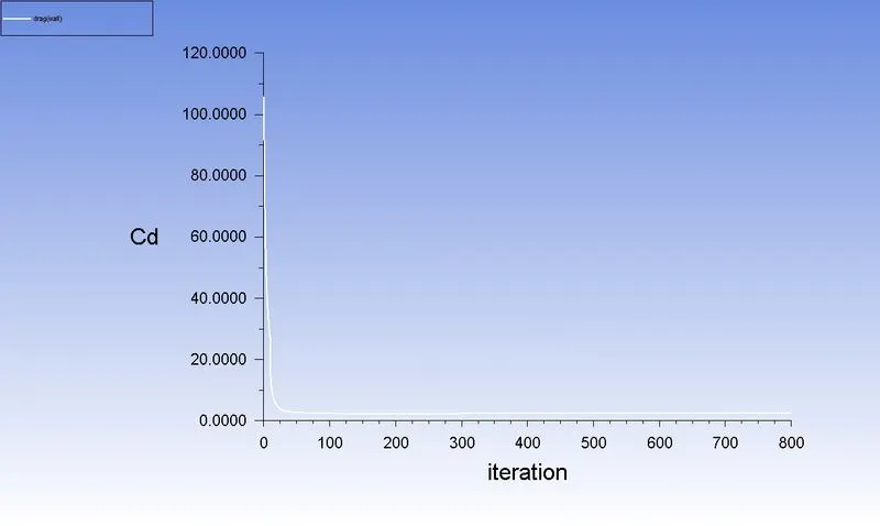
In fluid dynamics, the Co-efficient of drag(Cd) is a dimensionless quantity that is used to quantify the drag or resistance of an object in a fluid environment, such as air or water. It is used in the drag equation in which a lower drag coefficient indicates the object will have a less aerodynamic or hydrodynamic drag. The drag coefficient is always associated with a particular surface area.
The drag coefficient of any object comprises the effects of the two basic contributors to fluid dynamic drag: skin friction and form drag. The drag coefficient of a lifting airfoil or hydrofoil also includes the effects of lift-induced drag. The drag coefficient of a complete structure such as an aircraft also includes the effects of interference drag.
The drag coefficient Cd is defined as
`C_d=(2 .F_d)/(ρu^2 A)`
Where,
Fd is the drag force, which is by definition the force component in the direction of the flow velocity,
`ρ` is the mass density of the fluid,
u is the flow speed of the object relative to the fluid,
A is the reference area.
3.Co-efficient of lift:
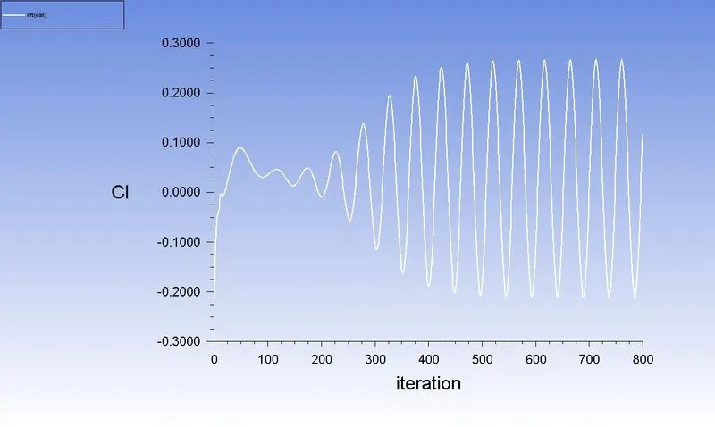
The Co-efficient of lift (Cl) is a dimensionless coefficient that relates the lift generated by a lifting body to the fluid density around the body, the fluid velocity, and an associated reference area. A lifting body is a foil or a complete foil-bearing body such as a fixed-wing aircraft. Cl is a function of the angle of the body to the flow, its Reynolds number, and its Mach number. The section lift coefficient Cl refers to the dynamic lift characteristics of a two-dimensional foil section, with the reference area replaced by the foil chord.
`c_l=L/qS`
Where,
L is the lift force,
S is the relevant surface area and
q is the fluid dynamic pressure
4.Reynolds Number:
Reynolds number is a dimensionless quantity that is used to determine the type of flow pattern as laminar or turbulent while flowing through a pipe. Reynolds number is defined by the ratio of inertial forces to that of viscous forces.
`R_e =(ρVL)/μ`
Where,
R_e = Reynolds Number.
`ρ`- Density.
`V`-Velocity.
`L`-Characteristic length in case of cylinder it is Diameter.
`µ`-Dynamic Viscosity
Case 1:
Simulate the flow with the steady and unsteady case and calculate the Strouhal Number for Re= 100.
Case 2:
Calculate the coefficient of drag and lift over a cylinder by setting the Reynolds number to 10,100,1000,10000 & 100000.
Procedure:
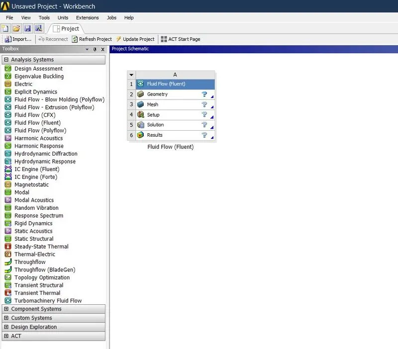
- Open Ansys workbench and drag the Fluid Flow(Fluent) to main window.
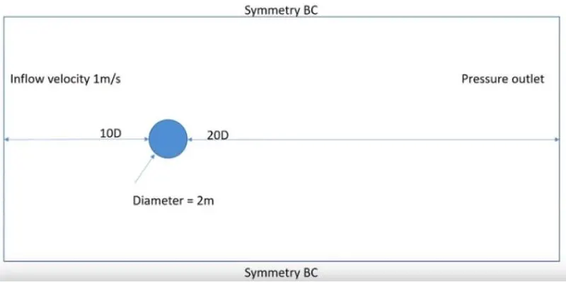
- Click on geometry to create a required geometry.
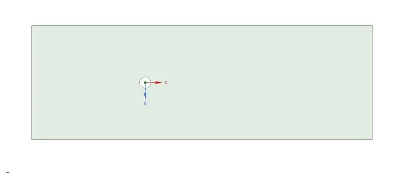
- Then update geometry in main window. After that click mesh.
- Select the faces by using selecting face option then name the faces like “Inlet, Outlet, Wall, Symmetry”.
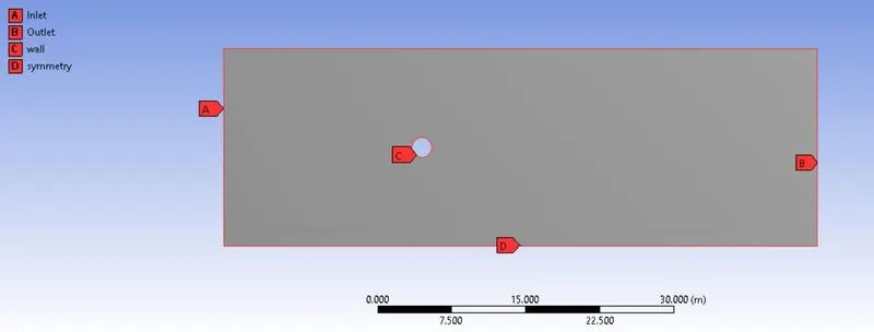
- Then go to the mesh enter the mesh size as 0.002. Then insert the automatic method mesh select the geomwtry change the type to triangular mesh. then insert the edge sizing mesh. After that generate the mesh. Check the quality of mesh that doesn’t goes less than 5%. Then update the mesh in main window.
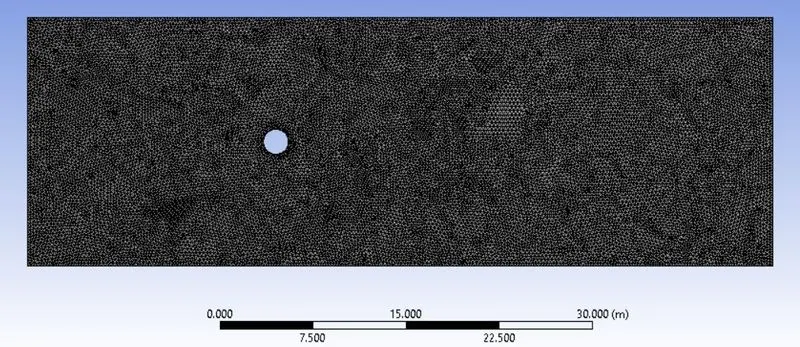
- After that go to the setup for setting up and solving the problem. After loading the geometry in graphics window change the appropriate units. Then check the mesh.
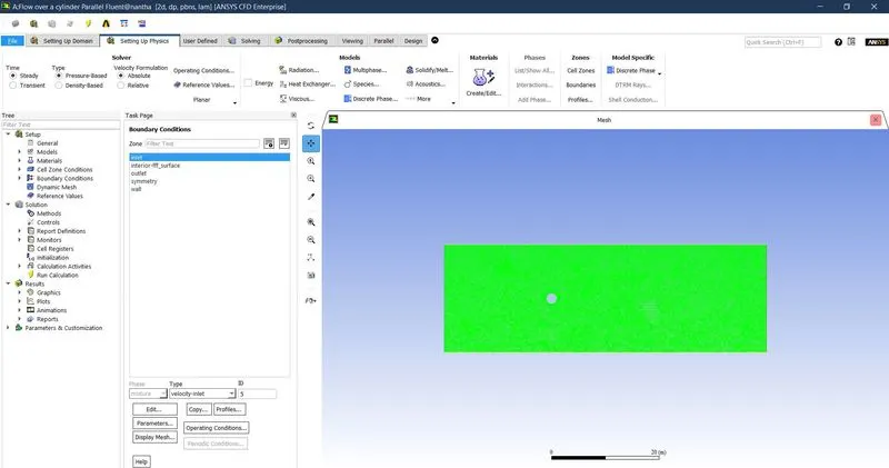
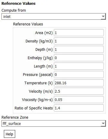
- Select Laminar model to solve. Then select the material as required. After that enter the boundary condition such as inlet velocity, temperature and pressure. Then initialize the solution and enter the no. of iteration then click calculate to run the simulation.
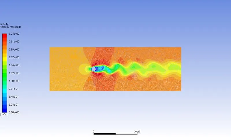
- In post processing create a contour plot for velocity and plot for Strouhal number.
- Create the animation to analyse the velocity distribution.
Outputs:
Case 1:
Simulate the flow with the steady case and calculate the Strouhal Number for Re= 100.
`∴V=(R_e.μ)/(ρ.L) = 100*0.05/1*2 = 2.5 m/sec`
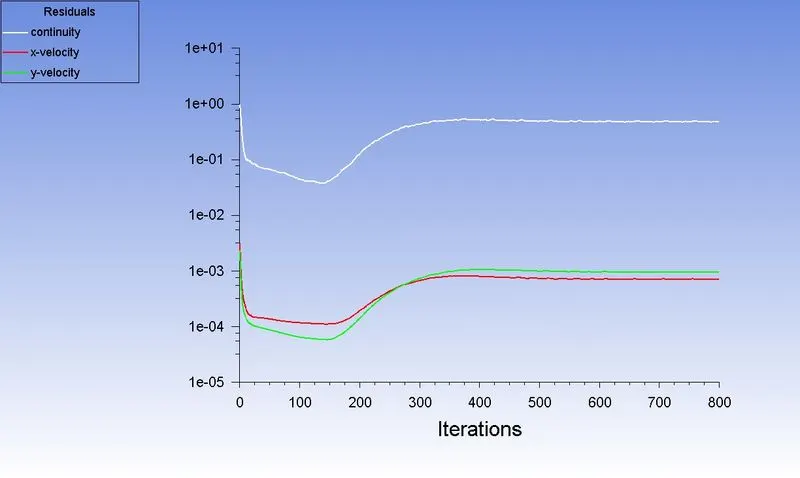
Residual:
Coefficient of Drag:
Coefficient of Lift:
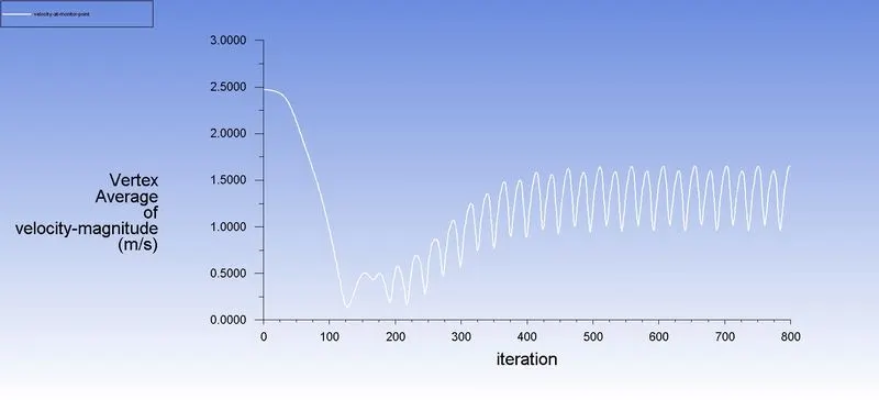
Vertex Average:
Velocity Contour:
Strouhal Number:
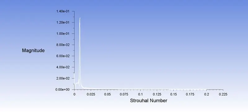
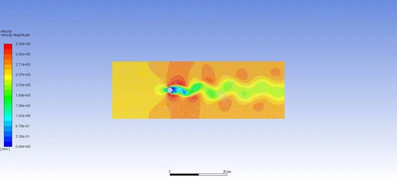
Simulate the flow with the unsteady case and calculate the Strouhal Number for Re= 100.
`∴V=(R_e.μ)/(ρ.L) = 100*0.05/1*2 = 2.5 m/sec`
Residual:
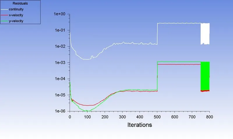
Coefficient of Drag:
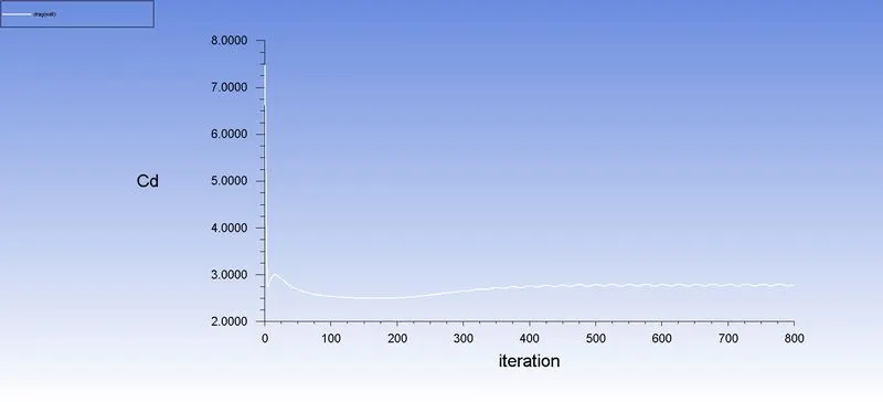
Coefficient of Lift:
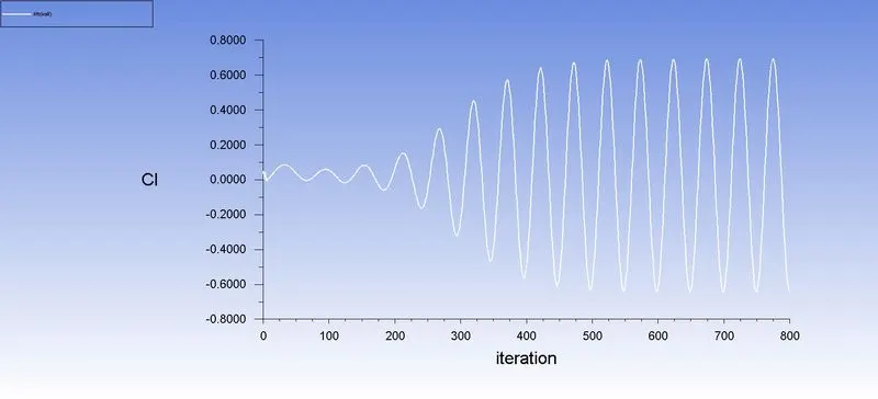
Vertex Average:
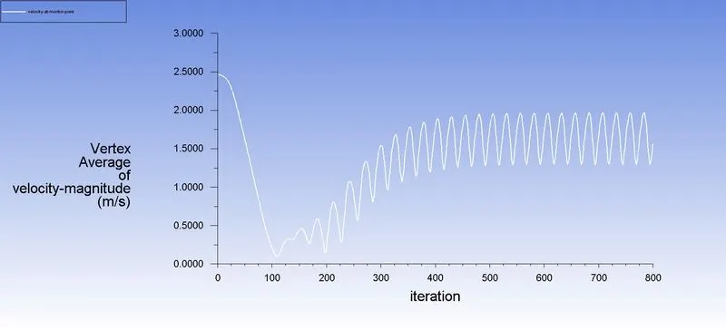
Velocity Contour:
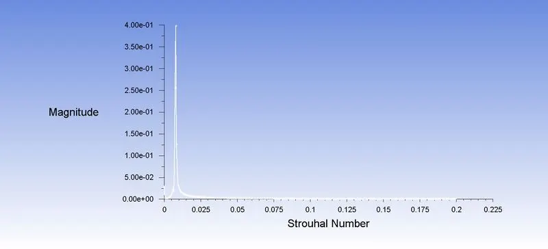
Strouhal Number:
| Solver | Coefficient of Drag | Coefficient of Lift | Strouhal Number |
| Steady State | 1 | 0.75 | 1.2e-1 |
| Unsteady State | 2.5 | 0.45 | 4e-1 |
| Experimental value | 1.30 | 0.045 | - |
Case 2:
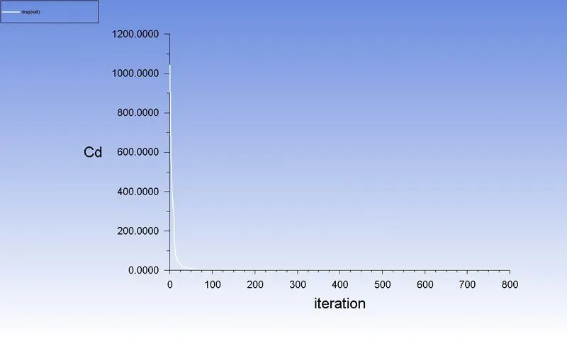
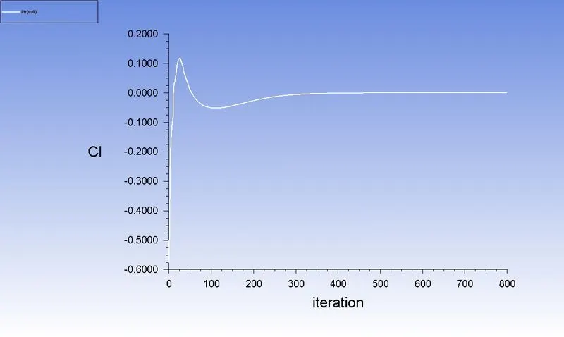
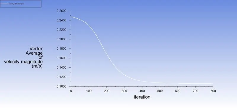
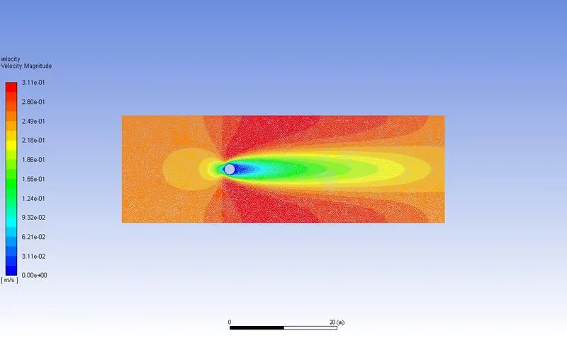
Reynolds number =10
Residual:
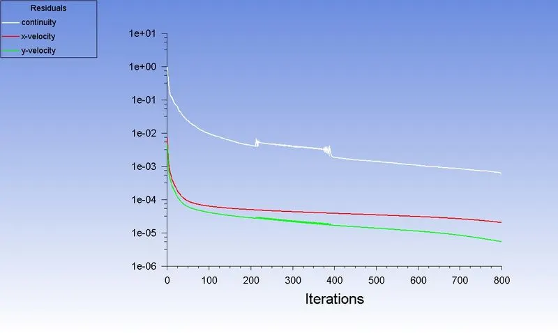
Coefficient of Drag:
Coefficient of Lift:
Vertex Average:
Velocity Contour:
Reynolds number =100
Residual:
Coefficient of Drag:
Coefficient of Lift:
Vertex Average:
Velocity Contour:
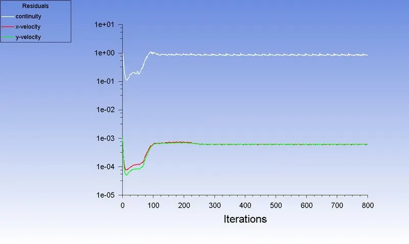
Reynolds number =1000
Residual:
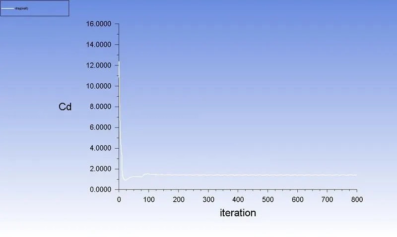
Coefficient of Drag:
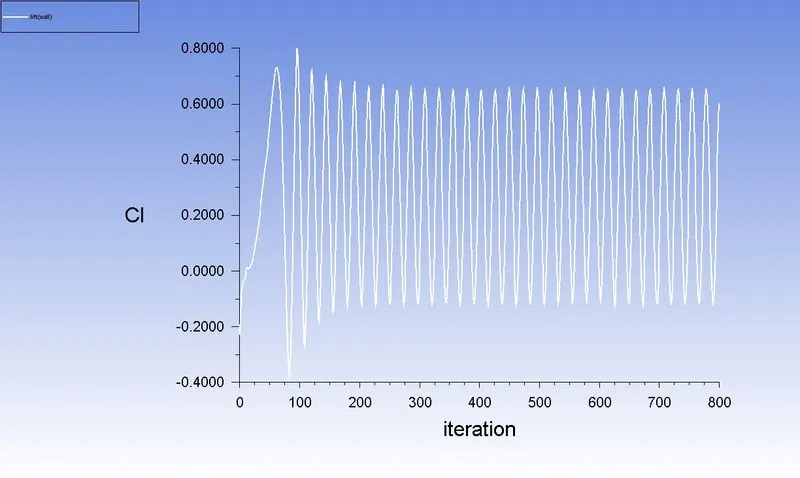
Coefficient of Lift:
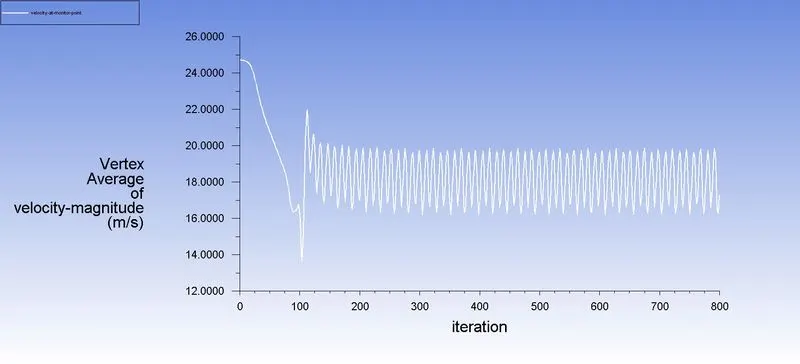
Vertex Average:
Velocity Contour:
Reynolds number =10000
Residual:
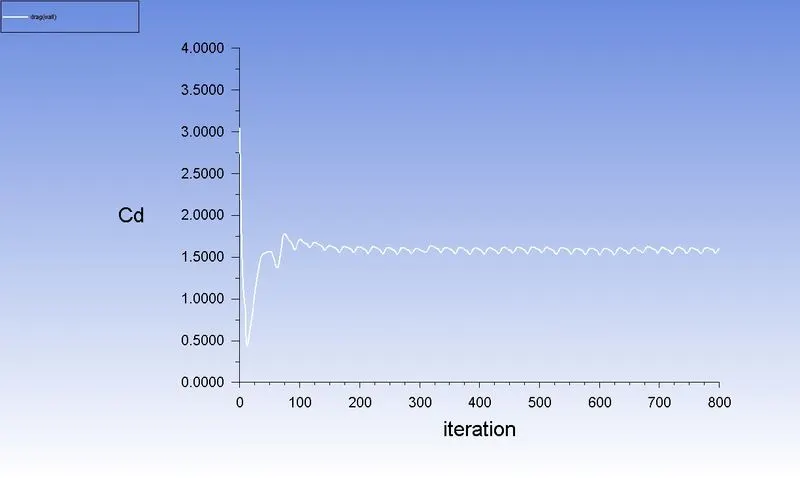
Coefficient of Drag:
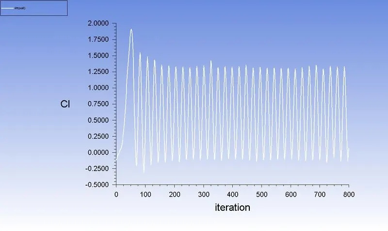
Coefficient of Lift:
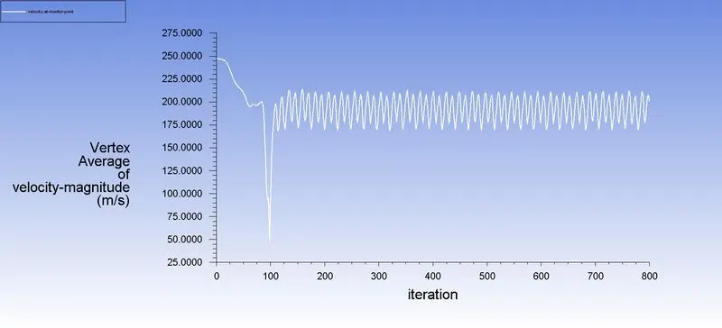
Vertex Average:
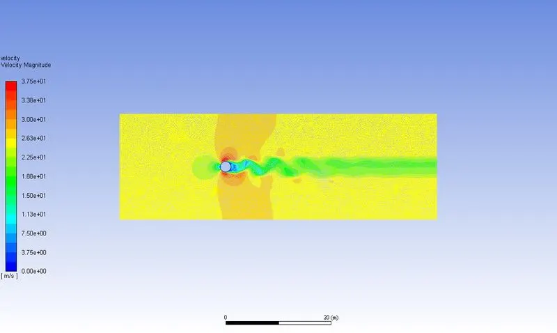
Velocity Contour:
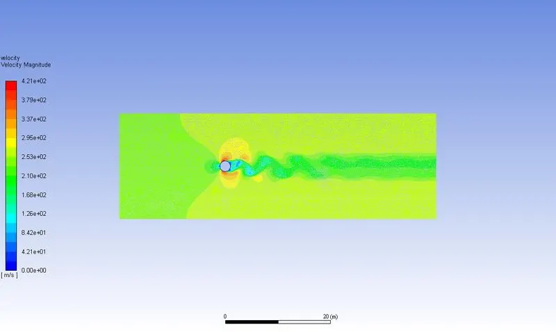
Reynolds number =100000
Residual:
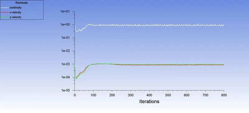
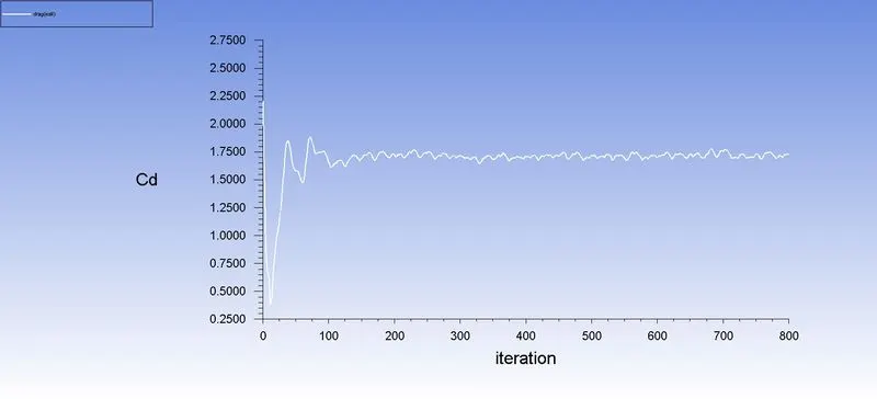
Coefficient of Drag:
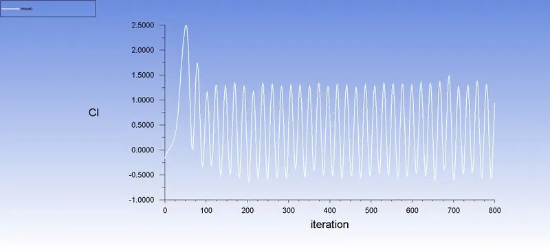
Coefficient of Lift:
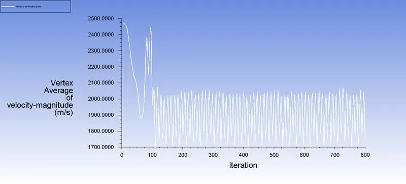
Vertex Average:
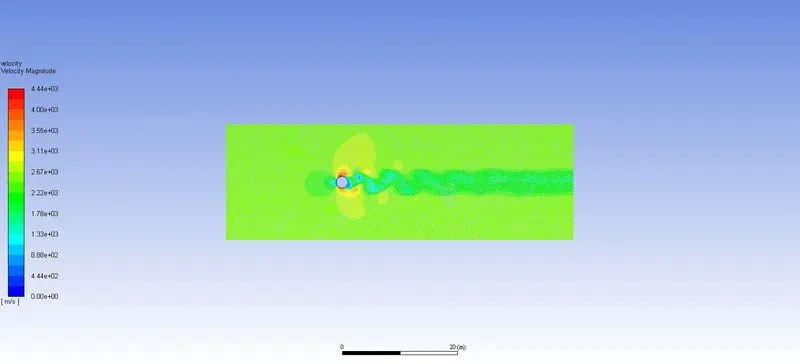
Velocity Contour:
| Reynolds Number | Coefficient of Drag | Coefficient of Lift |
| 10 | 1 | 0.1 |
| 100 | 1 | 0.75 |
| 1000 | 1.45 | 0.59 |
| 10000 | 1.55 | 0.57 |
| 100000 | 1.6 | 0.55 |
- If we compare the data in the table, it is seen that as Reynolds number is increasing the coefficient of Drag is decreasing and coefficient of lift is increasing. This phenomenon is happening because of when Reynolds number get increased the surface friction between fluid and cylinder is also increasing which casue the boundary layer to break before flow seperated hence amount of drag get decreases and lift get increases.
- As the Reynolds number increase in value the wake region behind the cylinder is also increasing which results in bigger domain capturization for further simulations. For lower Reynolds number the vortices are bit symmetrical in nature but as Reynolds number get increase it start to deviate more.