Radar Mast & Final Assembly of Yacht
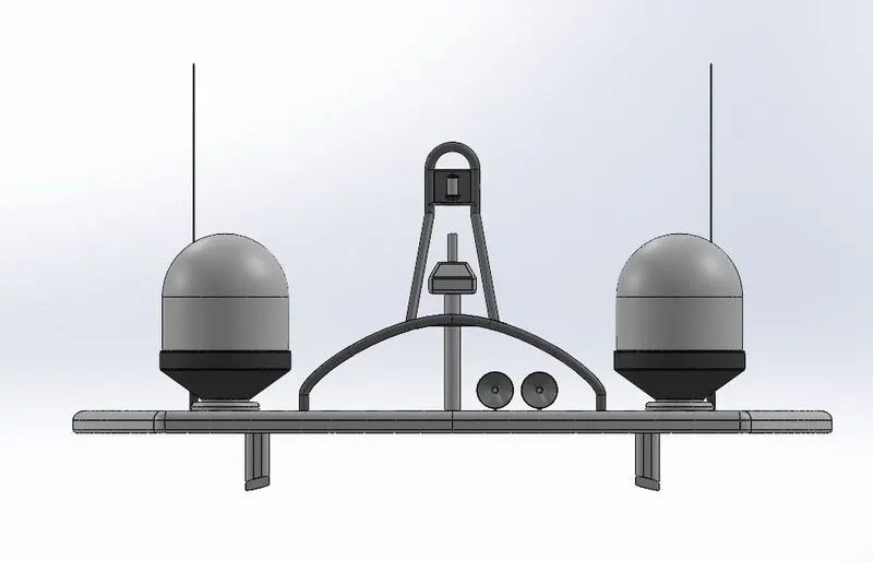
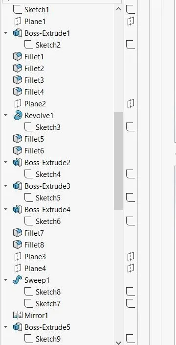
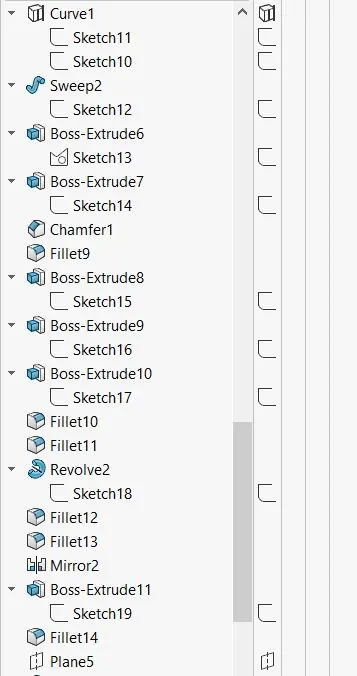
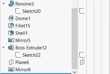
1. Radar Mast
Front View
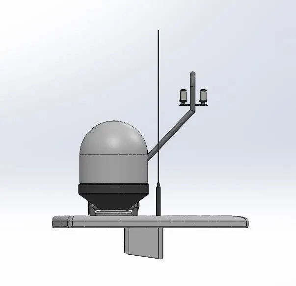
Side View
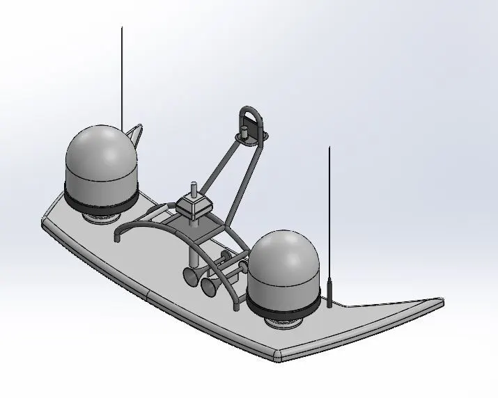
Isometric View
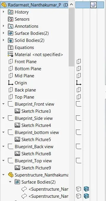
Feature View
2. Yacht Assembly
Front View
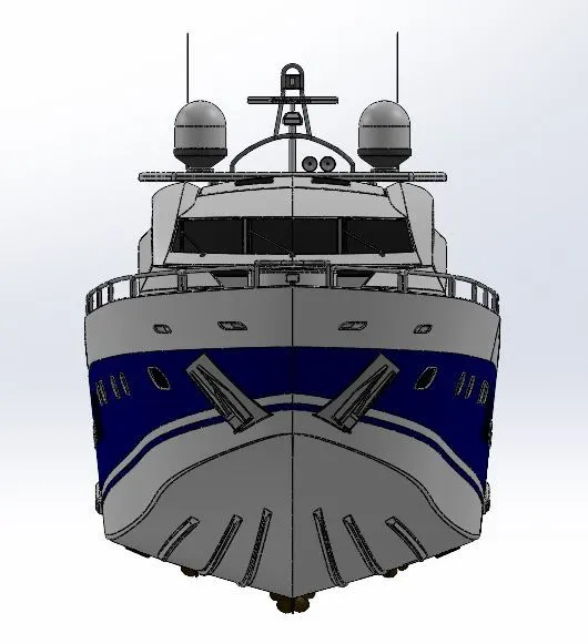
Side View
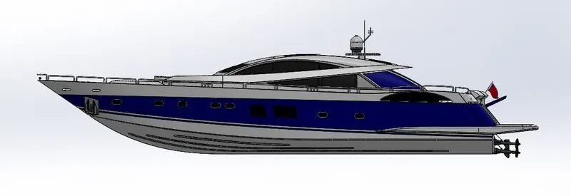
Isometric View
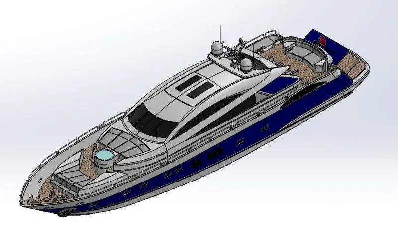
Feature View
Design of Yacht
Objective:
To design a Yacht from concept of sketch to fully defined model for final rendering using “SOLIDWORKS and SOLIDWORKS Visualize” software.
Introduction:
This report is fully about how to design a Yacht from,
- Do sketch to designing of parts with appropriate Dimensions.
- Create fully defined models of individual parts of the yacht by using -SOLIDWORKS features.
- Adding appearances to the all parts.
- Assembling all the fully defined parts of yacht using-SOLIDWORKS.
- Correcting the flaws in the assembled model
- Rendering the Yacht
Design Methodology –Flow Chart:
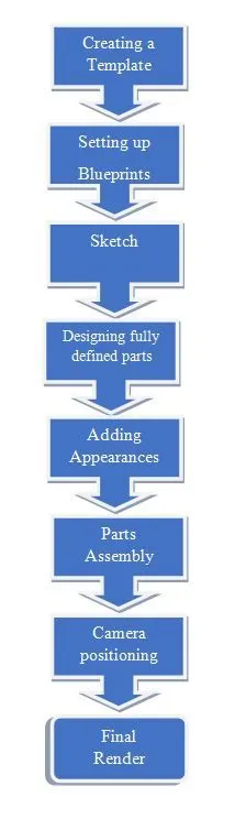
Template: To set up an appropriate dimension scale to design parts.
Setting up Blueprints: Import the blueprints of yacht and fix it with appropriate position.
Sketch: To create 2D sketch with required dimensions of parts.
Create fully defined parts: To create a 3D model or part with appropriate dimensions.
Appearance: After creating parts apply suitable appearance to the model.
Part assembly: Assemble all the individual parts into fully defined Yacht.
Camera: Add lights, camera view to the assembled Yacht.
Final render: To highlight the design of Yacht and the scenes and environments are set to the design for final render.
Parts to Design:
- Hull
- Super structure
- Radar
- Radar mast
- Front, Middle and Rear seat
- Propeller
- Garage door
Feature and Surface tools used:
Extrude Boss/Base:
This feature will allow you to convert 2D sketch into the 3D model with the help of adding thickness to it with appropriate dimensions
Extrude Cut:
This feature is used to remove the material from the part by projecting a sketch section normal to the plane.
Revolved Boss/Base:
This feature is used to create a 3D model around the axis.
Revolved Cut:
This feature is used to remove materials from 3D models possess axis symmetry or remove materials by revolving a closed profile along an axis.
Swept Boss/Base:
This feature is used to create 3D product design parts by sweeping like curved rods, tubes, hollow pipes etc.
Swept Cut:
This feature is used to cut a solid model or part by sweeping a completely closed profile along on open or closed path.
Lofted Boss/Base:
This feature is used to add materials between two or more profiles with ease.
Fillet:
It creates a rounded internal or external face on the part. It is mainly used on the edges and corners of faces or parts.
Chamfer:
This feature creates a beveled feature on selected edges, faces or a vertex. It is used to create sloped or angled edges.
Linear Pattern:
This feature is used to create multiple instances of one or more feature tha we can space uniformly along one or two linear paths.
Circular Pattern:
This feature is used to create multiple instances of one or more feature tha we can space uniformly around the axis.
Curve Driven Patter:
This feature is used to create pattern along a plane or 3D curve.
Mirror:
This feature is used to creates a copy of a feature and mirrored about a face or a plane.
Shell:
This feature is used to create a hollow space within a solid part according to its thickness value given, mainly used in tank designs.
Project Curve:
This feature is used to create projection of two sketch in different intersecting planes and this curve is used s pat for sweep.
Composite Curve:
This feature is used to combine curves, sketch geometry and model edges into a single curve and this created curve is used as a guide curve for creating a loft or a sweep.
Split Line:
This tool projects a entity sketch, solid, surface, face, plane or surface spline) to surface, or curved or plane faces.
Reference Plane:
This feature is used to create a plane within the sketches.
Dome:
This feature is used to create a hollow sphere that is tangent to the adjacent cylindrical or conical face.
Split:
This feature is used to create multiple parts from n existing part (or) you can split one or more solid or surface bodies.
Combine:
This feature is used to add two or more bodies together and keep the area that is common to them.
Move/Copy:
This feature is used to move, rotate, copy -solid and surface bodies, or place those using mates with the help of this feature tool.
Lofted Surface:
This feature is used to create surfaces with a smooth tangency between the selected curves by multiple 3D curve r existing edges.
Knit Surface:
This feature is used to combine two or more faces and surfaces into one.
Extruded Surface:
This feature is used to create surface of the selected sketch.
Sweep Surface:
This feature is used to create a surface with the help of sketch as the profile and the path.
Ruled Surface:
This feature is used to extend the surface which is already existed.
Fill surface:
This feature is used to fill the surface to complete the solid body with the help of sketches.
Extent surface:
This feature is used to extend the surfaces with tangency between the existed surfaces.
Trim Surface:
This surface is used to cut or delete the unwanted surface.
1.Hull:
A hull is the waterweightbody of a ship or boat. The hull may open at the top or it may be fully or partially covered with a deck. A top the deck may be a deckhouse and other superstructure, such as a radar mast. The line where the hull meets the water surface is called the waterline.
Sketch tools used:
- Line
- Arc
- Circle
- Spline
- Rectangle
- Ellipse
- Straight slot
- Convert entities
- Offset entities
- Smart dimensions
Feature tools used:
- Extrude boss
- Extrude cut
- Revolve boss
- Swept boss
- Fillet
- Chamfer
- Mirror
Surface tool used:
- Extrude
- Revolve
- Sweep
- Loft
- Ruled surface
- Fill
- Extend
- Trim
- Knit
Appearance: Required paint appearance.
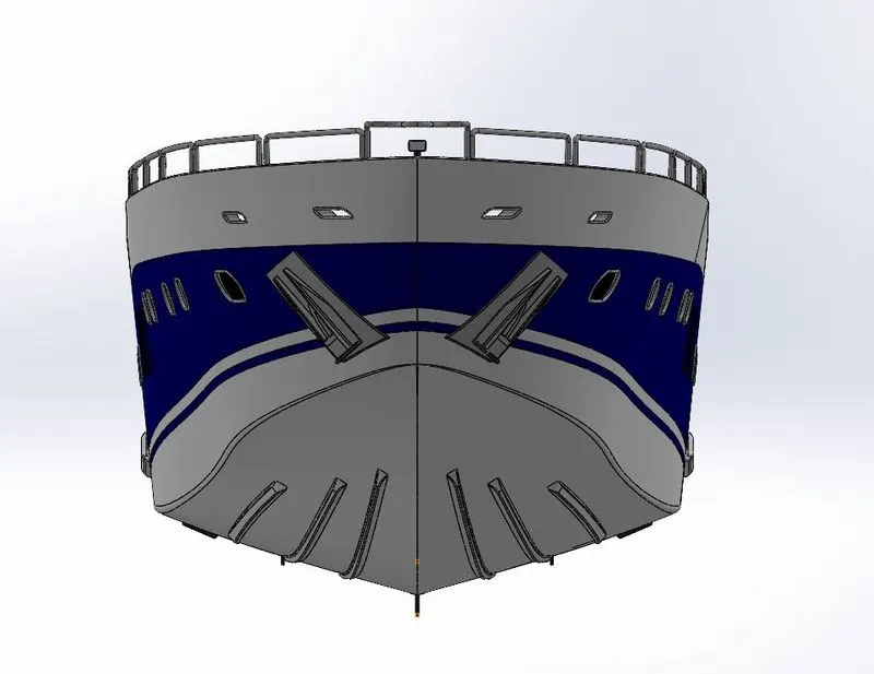
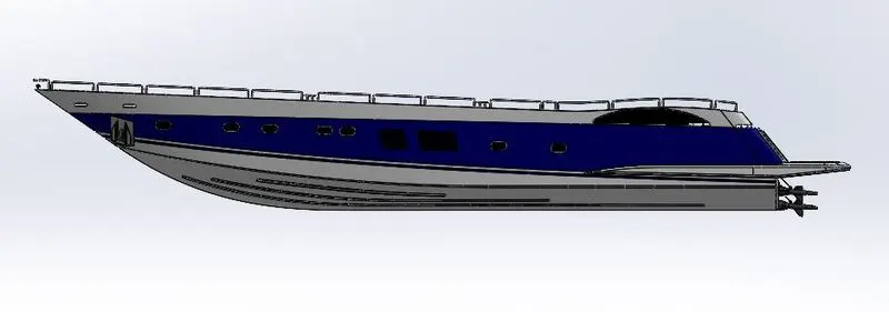
Front View Side View
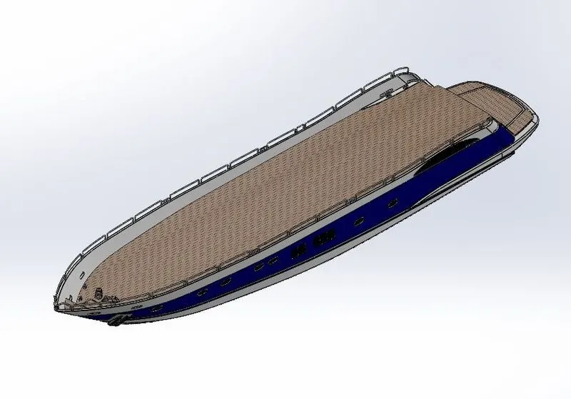
Isometric View
- Super Structure:
A superstructure is an extended construction of any building or platform that rises above the rest of the building or platform in a distinct manner. Thus , superstructure means to add a construction to already existing structure. In ships this is name given to the part of the ship emerges from the deck. In many ships the superstructure is broader and bigger in size and area.
Sketch tools used:
- Line
- Arc
- Circle
- Spline
- Rectangle
- Ellipse
- Straight slot
- Convert entities
- Offset entities
- Smart dimensions
Feature tools used:
- Extrude boss
- Extrude cut
- Revolve boss
- Swept boss
- Fillet
- Chamfer
- Mirror
Surface tool used:
- Extrude
- Revolve
- Sweep
- Loft
- Ruled surface
- Fill
- Extend
- Trim
- Knit
Appearances: Required paint appearance.
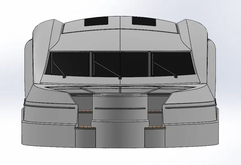
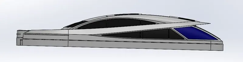
Front View Side View
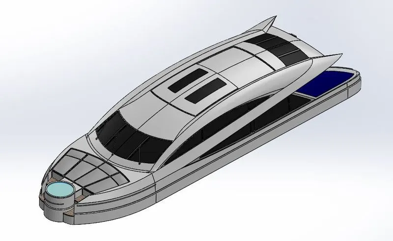
Isometric View
- Radar & Mast
A radar marine device acts as a major navigation aid for boaters. It helps in detecting boats, birds, landmasses, and weather system – even if the visibility is less than usual. Radar is a vital navigation component for safety at sea and near the shore.
Sketch tools used:
- Line
- Arc
- Circle
- Spline
- Rectangle
- Ellipse
- Straight slot
- Convert entities
- Offset entities
- Smart dimensions
Feature tools used:
- Extrude boss
- Extrude cut
- Revolve boss
- Swept boss
- Fillet
- Chamfer
- Mirror
Appearances: Required paint appearance.
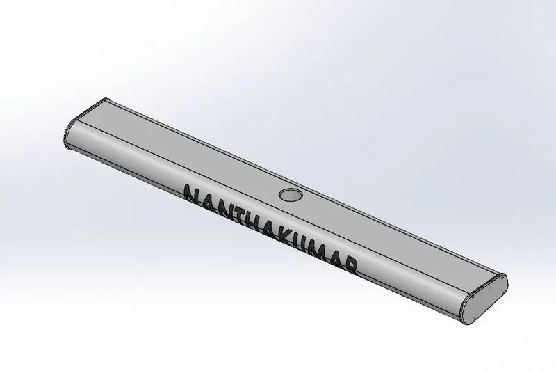
Radar &Mast
- Front, Middle & Rear Seat:
There are three types of seats arranged in yacht. The front sea accommodates with two persons, middle seat accommodated with three persons, and rear seat is provide accommodated with more persons.
Sketch tools used:
- Line
- Arc
- Circle
- Spline
- Rectangle
- Convert entities
- Offset entities
- Smart dimensions
Feature tools used:
- Extrude boss
- Extrude cut
- Fillet
- Chamfer
- Mirror
Surface tool used:
- Extrude
- Loft
- Fill
- Extend
- Trim
- Knit
Appearances: Required paint appearance.
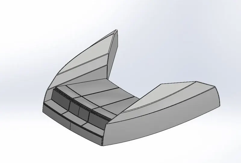
Front Seat
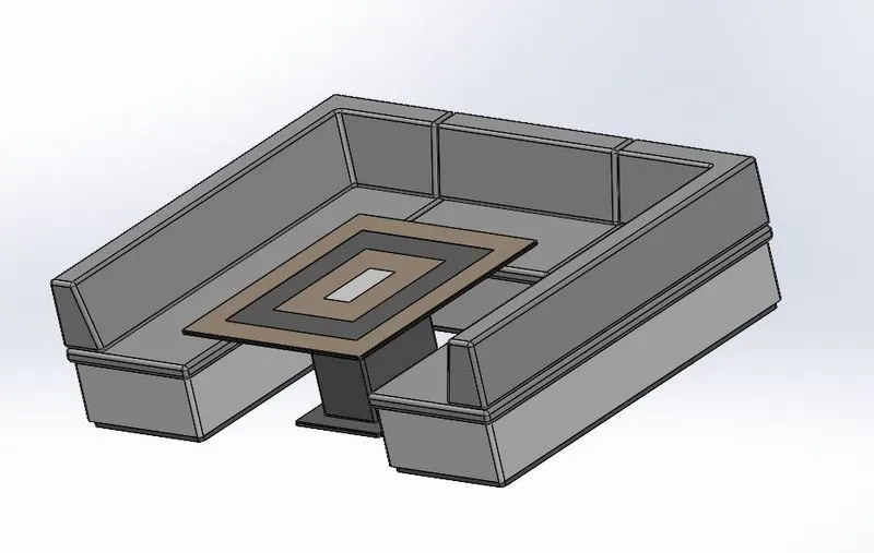
Middle Seat
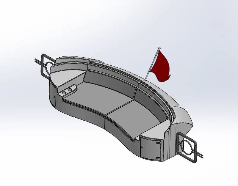
Rear Seat
- Propeller:
Propeller blades displace water, to create the forces that move a boat forward. The basic propeller shaft creates the torque, or energy required to turn the blades. But, the design of propeller blades is what creates the displacement of water. The displacement of water is what creates forces that move a boat forward.
Sketch tools used:
- Line
- Arc
- Circle
- Spline
- Rectangle
- Smart dimensions
Feature tools used:
- Extrude boss
- Extrude cut
- Revolve boss
- Swept boss
- Fillet
- Chamfer
- Mirror
Appearances: Required paint appearance.
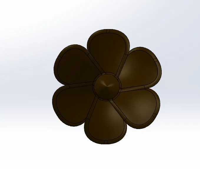
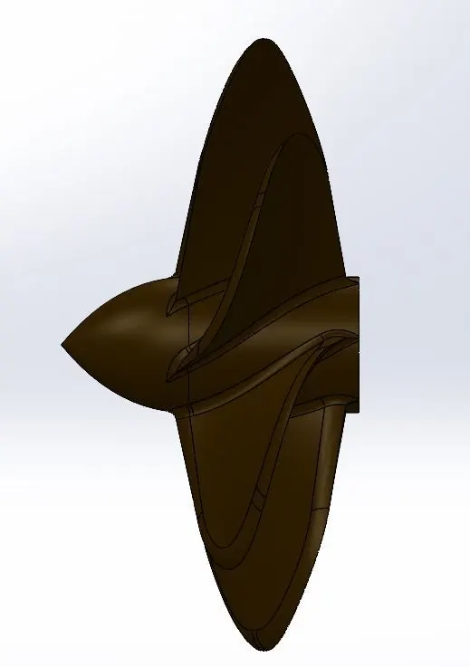
Front View Side view
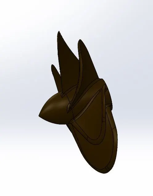
Isometric View
- Garage door:
Garage door is used to store the materials, items and vehicles etc..
Sketch tools used:
- Line
- Arc
- Circle
- Rectangle
- Smart dimensions
Feature tools used:
- Extrude boss
- Extrude cut
- Fillet
- Chamfer
- Mirror
Appearances: Required paint appearance.
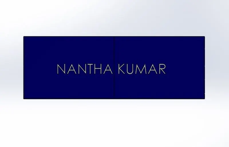
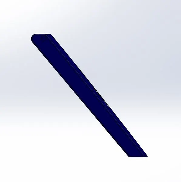
Front View Side View
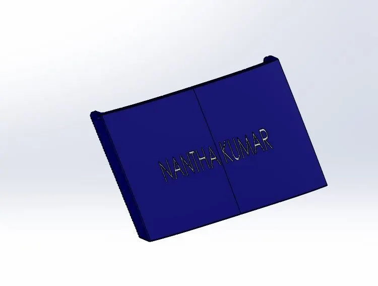
Isometric View
Assembly:
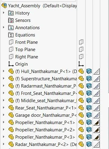
- First open solid works window then select assembly.
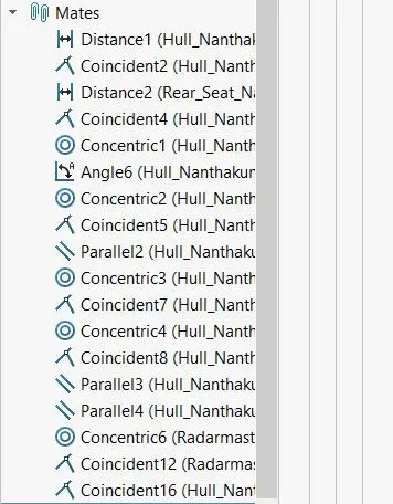
- The previously designed parts are opened to assemble them by applying mates to appropriate planes and geometry in the assembly window.
- First we have to fix the hull portion with the assembling window, then the superstructure, Radar mast, Front seat, Middle seat and Rear seat gets matted automatically.
- Then fix the garage door by using concentric mate.
- Then fix propeller by using concentric and coincident mates
- Then fix radar by using concentric and coincident mates.
Front View
Side View
Top View
Isometric View
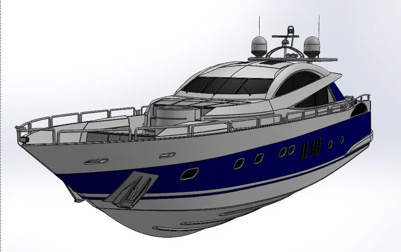 Camera View
Correcting the flaws in the assembly:
After assembling the parts, check for any flaws like parts overlapping. If any flaws were identify them and correct it, by changing the geometry of parts in the part level.
Final Render:
Photoview 360 feature in SOLIDWORKS is used to add some lights and camera view in the render window for the final render.
To highlight the design of Yacht and the scenes and environments are set to the design for final render.
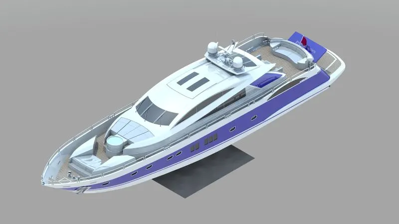
Photo Realistic Rendering:
By using “SOLIDWORKS VISULIZE” rendering software, the appearance of the design changed and the real time ‘hdr’ scenes added as the environment to design, to make the design merged with this environment for photo realistic rendering.
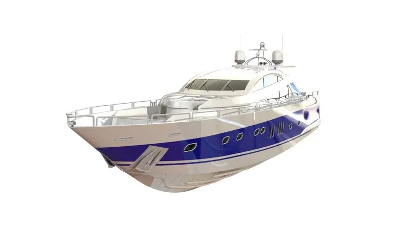
Conclusion:
In this project there are two main software’s used to make the Yacht. One is SOLIDWORKS to design the parts required for assembly of an Yacht and SOLIDWORKS VISULIZE which is used to render the assembly of Yacht. In this project a design was inspired from the visual presentation to make a concept sketch of model to design the parts with required dimensions and features. Then the designed parts are assembled to form a Yacht and its flaws are corrected. After this process apply decals, lights and camera view to make the model more realistic to render.