Week 3 - External flow simulation over an Ahmed body.
Aim:
- To perform external flow simulation over Ahmed Body.
Description:
Ahmed body:
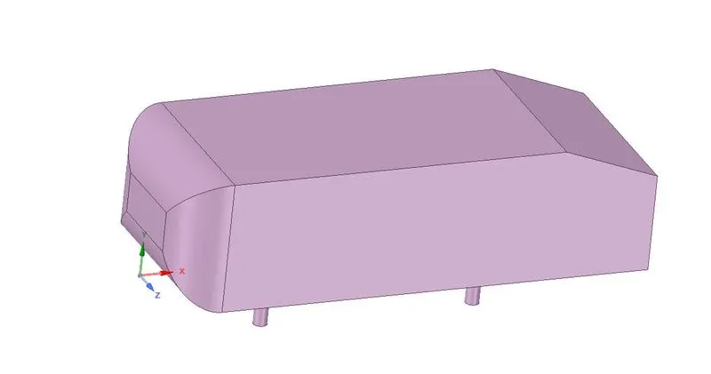
- The Ahmed body was first created by S.R. Ahmed. It is an important benchmark for aerodynamic simulation tools. It will be clearly shown in the sketch below that it has a length of 1.044 meters, the height of 0.288 meters and the width of 0.389 meters. It also has a 50 millimeter cylindrical legs attached to the bottom of the body and the rear surface which has a slant that falls of at 35 degrees.
- The flow for the model is turbulent which is based on velocity and body length. For the default mesh size in ANSYS-FLUENT we will use `k − ε` model and for the later stage`k − ω SST` model is used.
Importance of Ahmed body
- The drag force is an important factor considering fuel consumption. As the drag force increases the fuel consumption also increases which in turn becomes expensive for the car owners. As the burning of fossil fuels becomes an issue, the manufacturers are pressing for fuel-efficient cars. One of the main factors considering the car is fuel-efficient or not is the car's geometry.
- Complex shaped cars are very challenging to model and its difficult to quantify the aerodynamic drag computationally. The Ahmed body is a benchmark model widely used in the automotive industry for validating simulation tools.
Negative pressure in the wake region
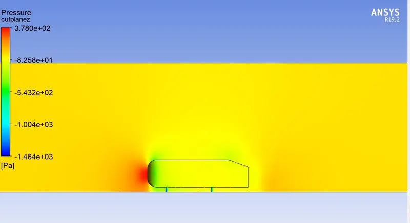
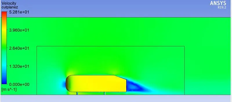
- When the air moving over the vehicle is separated at the rear end, it leaves a large low-pressure turbulent region behind the vehicle which is known as the wake. This contributes to the formation of pressure drag which affects the vehicle performance.
- When the vehicle is moving at a certain velocity the fluid imparts viscous force to the vehicle as long as it is in the viscous sublayer of the boundary. When the fluid reaches the rear end of the vehicle it gets detached from the surface of the body causing negative pressure in the wake region. The movement of the fluid around the vehicles depends on the geometry of the car and the Reynolds number.
Significance of point of separation
- The point of separation will occur when there is a discontinuity in the surface or a region of the negative pressure gradient (a sharp end or rear portion of the car).
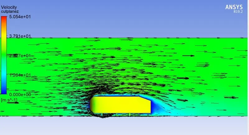
- When the flow is attached to the body of the vehicle the viscous force will increase which will increase the pressure and a decrease in velocity before the rear end of the vehicle. As soon as the air encounters the sharp turn causing the velocity to decrease resulting in the negative pressure region which is in the wake region. The recirculation region happens beyond the point of separation.
- If the rate of change of pressure is large the mixing process will not occur and the boundary layer flow stops.
- The above figure shows that at the point of turning the flow gets separated from the boundary layer and there is a region of recirculation after which the flow attaches itself to the boundary layer.
- In order to reduce the separation of fluid from the boundary layer, it is advisable to have a smooth edge to reduce the effect of drag on the vehicle.
Procedure:
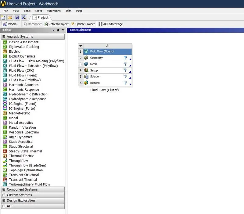
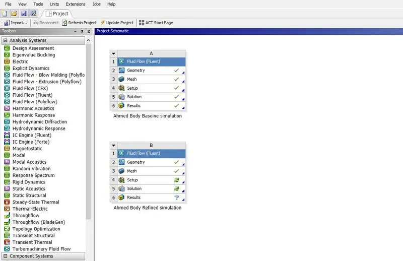
- Open Ansys workbench and drag the Fluid Flow(Fluent) to main window name as Ahmed Body Baseline simulation.
- Click on geometry to import the geometry file.
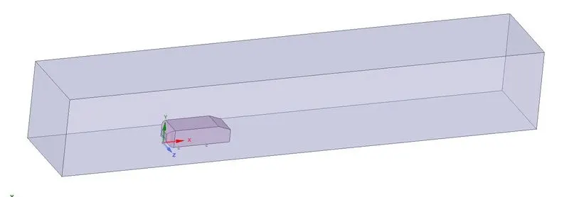
- Then select the first enclosure with appropriate dimensions.
- Then update geometry in main window. After that click mesh.
- Select the faces by using selecting face option then name the faces like “Inlet, Outlet, symmetry-wall,car wall ”.
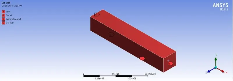
- Then go to the mesh generate the mesh with defauld setting for baseline simulation. Check the quality of mesh that doesn’t goes less than 5%.
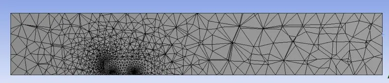
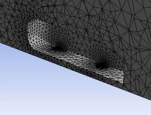
- Then update the mesh in main window.After that go to the setup for setting up and solving the problem. After loading the geometry in graphics window change the appropriate units. Then check the mesh.
- Select k-epsilon,Steady-state, the density-based solver model to solve. Then select the material as air. After that enter the boundary condition such as inlet velocity, temperature and pressure. Then initialize the solution and enter the no. of iteration then click calculate to run the simulation.
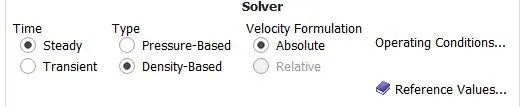
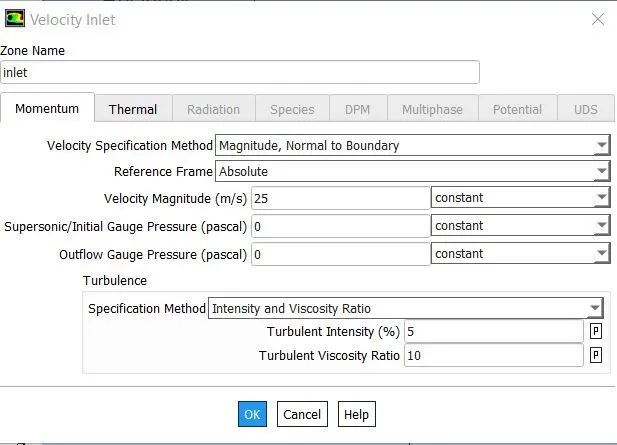
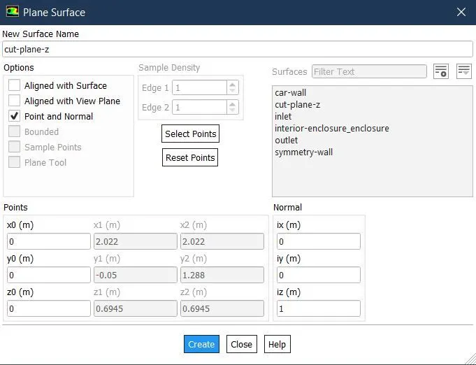
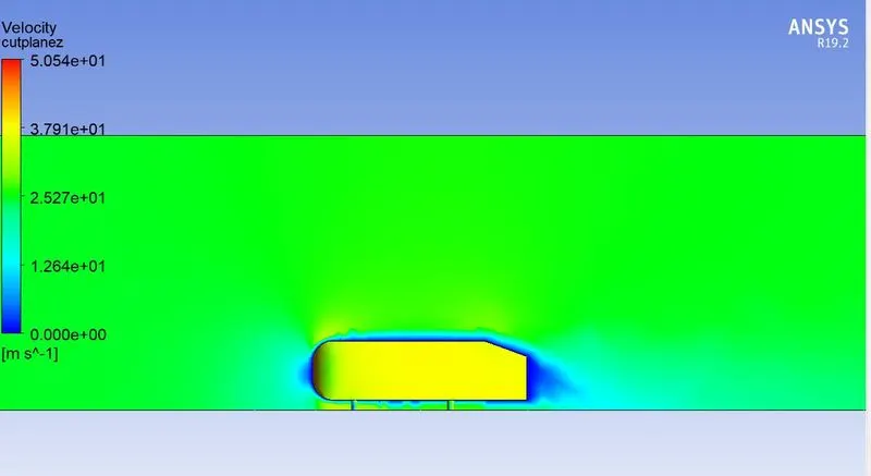
- Create cut-plane-z then create a velocity contour and pressure contour based on the cut-plane-z.
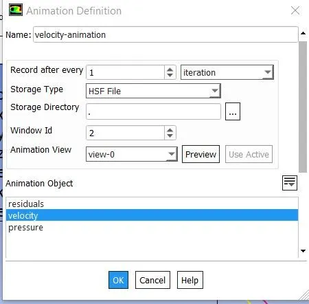
- Create a velocity animation.
- Update the solution in main window then go to results for the post processing.
- Create a xy plane to get the appropriate results.
- Then duplicate the baseline simulation file name as Ahme body Refined simulation.
- Then edit the geometry, create another enclosure for the refined simulation with appropriate dimensions.
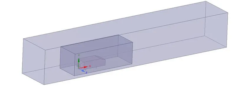
- And then check the interference between enclosures.
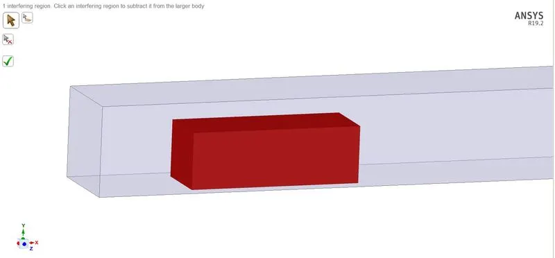
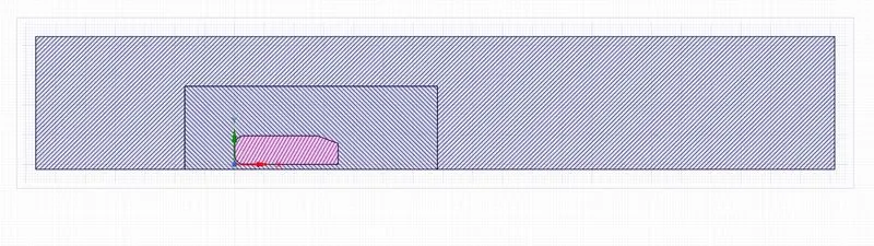
- Clear the existed data in mesh and reset the mesh then click mesh to crete a new mesh.
- Go to mesh enter mesh size as 100mm and the max size also 100 mm, insert method mesh select the first enclousre choose method as multizone and then insert sizing mesh select the second enclosure enter the element size as 50 mm then create another sizing mesh select the four round columns in the ahmed body enter mesh size as 5mm then generate the mesh for the first refined smulation.
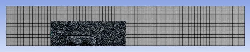
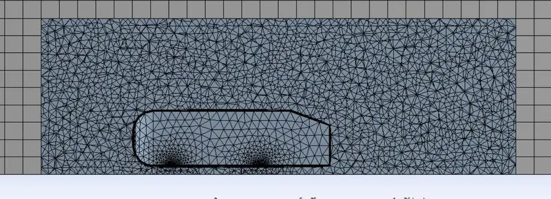
- After that repeat the same procedure as followed by baseline simulation to set uo and solve the refined simulation.
Meshing:
| Meshing Type | Method | Body Sizing | Face Sizing | Inflation | Nodes | Cell Counts |
| Baseline | - | - | - | - | 16654 | 8443 |
| 1st Refinement | Multizone(100mm) | Inner Enclosure(50mm) | Holes(5mm) | 12.5 mm on car wall | 60863 | 199701 |
| 2nd Refinement | Mulizone(80mm) | Inner Enclosure(40mm) | Holes(5mm) | 12.5 mm on car wall | 98943 | 333832 |
| 3rd Refinement | Multizone(70mm) | Inner Enclosure(35mm) | Holes(5mm) | 12.5 mm on car wall | 131919 | 464675 |
Results:
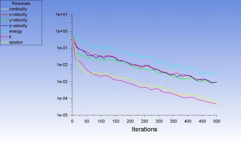
Baseline Simulation:
Residual:
Velocity Contour:
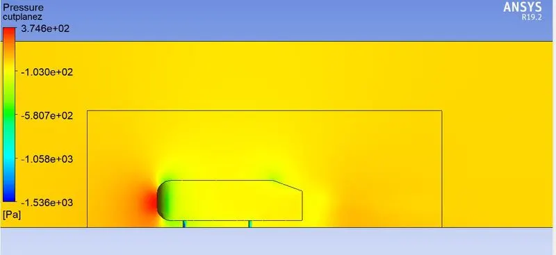
Pressure Contour:
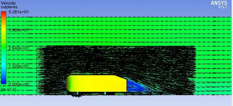
Vector:
1st Refined Simulation:
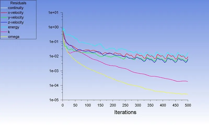
Residual:
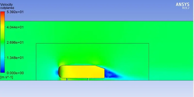
Velocity Contour:
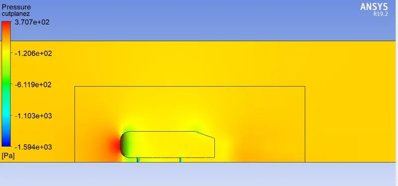
Pressure Contour:
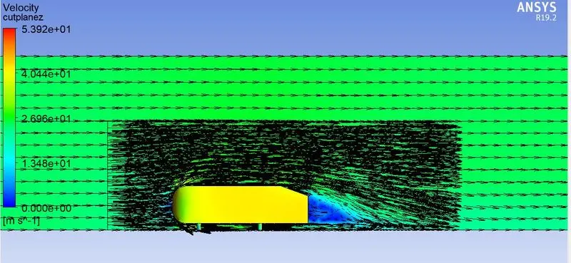
Vector:
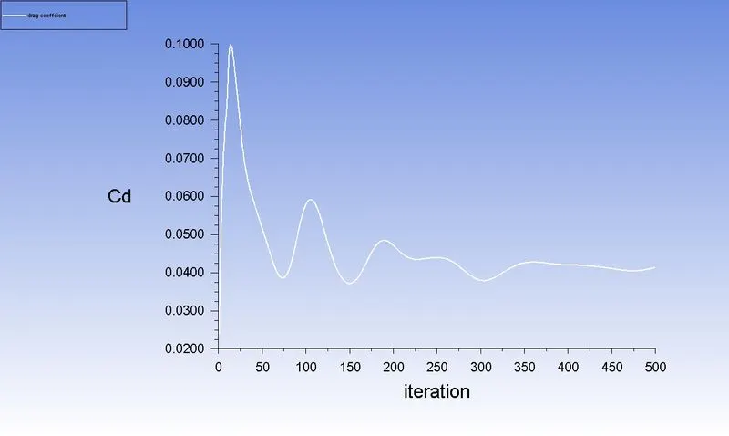
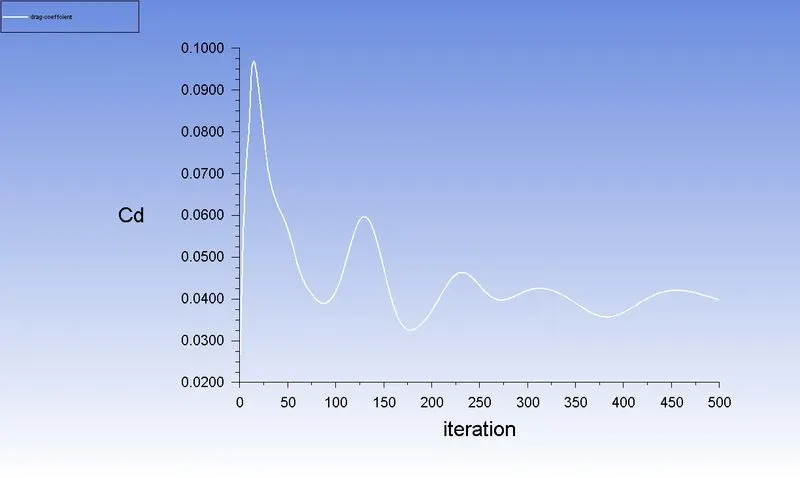
Drag Coefficient:
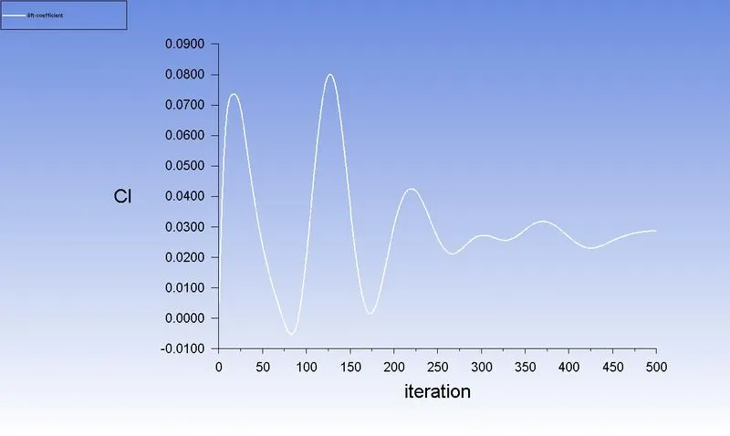
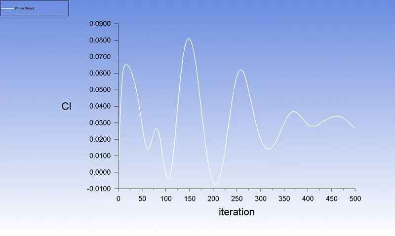
Lift Coefficient:
2nd Refined Simulation:
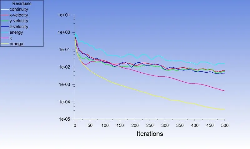
Residual:
Velocity Contour:
Pressure Contour:
Vector:
Drag Coefficient:
Lift Coefficient:
3rd Refined Simulation:
Residual:
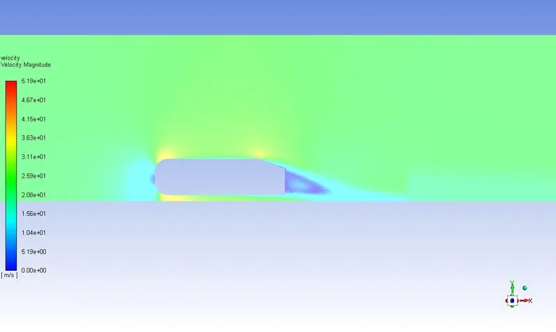
Velocity Contour:
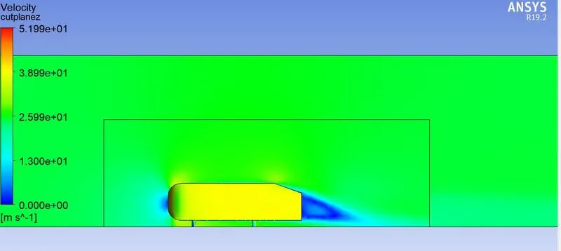
Pressure Contour:
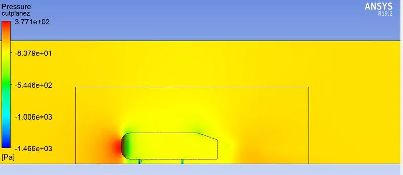
Vector:
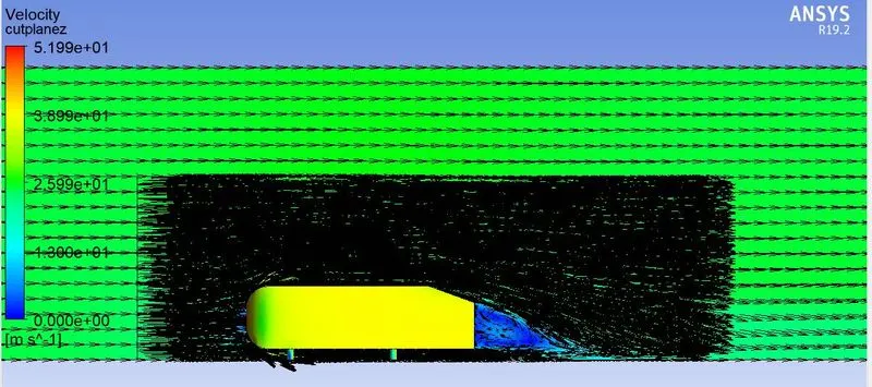
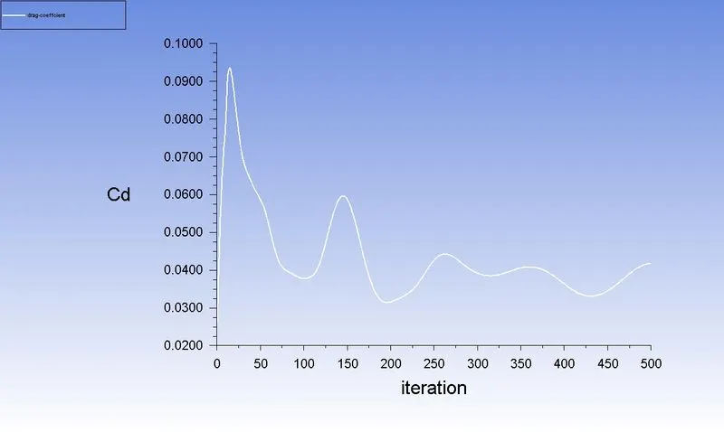
Drag Coefficient:
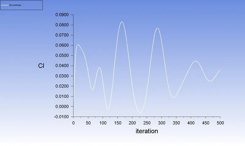
Lift Coefficient:
| Mesh Refinement | Drag Coefficient | Lift Coefficient |
| 1st Refinement | 0.041 | 0.025 |
| 2nd Refinement | 0.038 | 0.028 |
| 3rd Refinement | 0.04 | 0.039 |