Week 8 - Challenge 5 - Door Trim Lower
Door Trim Challenge:
Objective:
To Create the Door Trim Plastic component through the given Class-A surface. To begin with, the tooling axis for the given Class-A Surface should be created meeting the draft angle requirements and performing the draft analysis on the model at the end.
Take the Thickness of the component to be 2.5 mm
Introduction:
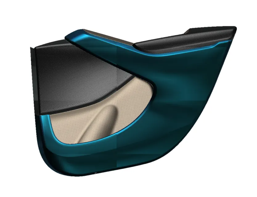
Door trim in a car refers to the molding or paneling around the interior and exterior edges of a car door. Its purpose is to protect the door from damage, provide a weather seal, and enhance the aesthetic appearance of the vehicle. The door trim can be made of various materials including plastic, vinyl, or metal, and is often customizable to match the interior or exterior of the car.
Types of Door Trim
There are several types of door trim used in cars:
-
Plastic Trim: This is a common and cost-effective option. It is lightweight and easy to install but can crack or fade over time.
-
Vinyl Trim: This type of door trim is durable and resistant to fading and cracking. It is a good choice for those who want an affordable option that will last a long time.
-
Wood Trim: This type of door trim provides a classic and sophisticated look, but is more expensive than plastic or vinyl options.
-
Aluminum Trim: This type of door trim is very durable and provides a sleek, modern look. It is often used in high-end vehicles.
-
Carbon Fiber Trim: This type of door trim is lightweight and extremely durable, making it a popular choice for high-performance and racing vehicles.
The type of door trim used in a car can vary depending on the make, model, and year of the vehicle, as well as the personal preferences of the owner.
Design Methodology:
Class A Surface:
The Class A surface is provided by the styling team, According to which the design engineer has to design the Class B and C surfaces. Also, it is the job of the design engineer to check whether the Class A surface is satisfying the draft analysis or not.
When a styling team provides a Class A surface to a design engineer, they are essentially providing a high-quality, visually appealing design for a specific part or component of a product. The Class A surface is created to meet the highest standards for appearance and quality, with no visible defects such as bumps, dents, or seams. The styling team uses advanced design techniques and technologies to create the Class A surface, taking into consideration the design requirements, materials, and manufacturing processes.
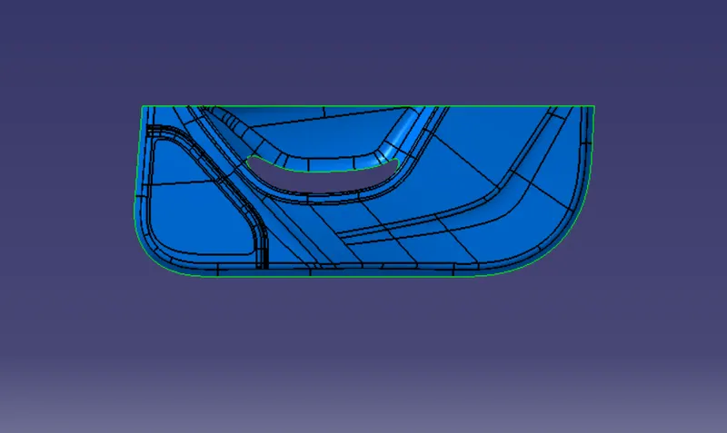
The design engineer then takes the Class A surface provided by the styling team and integrates it into the overall design of the product. This includes determining the best materials and manufacturing processes to use to achieve the desired Class A surface, as well as considering any functional or performance requirements that may impact the surface finish.
The collaboration between the styling team and the design engineer is crucial in ensuring that the Class A surface meets both the aesthetic and functional requirements of the product. By working together, they can create a high-quality product that meets the highest standards for appearance and performance.
Tooling Axis:
In this model the Tooling Axis is created by using the Normal to the Surface method, It is a method of creating the Tooling Axis in which we take a Plane Surface and extract it.
After that, we take a point on the surface at 0 and Create a line over it along the Y direction, As in the Y direction most of the part is visible and so it is the best possible direction for the Tooling Axis
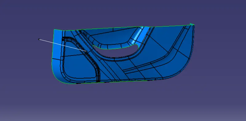
This method is simply based on Trail and Error method, if the model satisfies the draft Analysis using that Tooling Axis.
Draft Analysis:
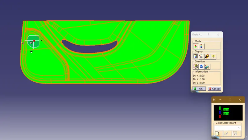
The next step is to check the draft angle of the Class A surfaces by using draft analysis draft analysis is used to determine the angle of the Class A surface relative to the mold or tooling used to manufacture the part. This angle, or draft, is crucial in ensuring that the Class A surface can be properly released from the mold during the manufacturing process, without causing any defects or damage to the surface finish.

It's important to accurately perform the draft analysis and check the Class A surface against the tooling axis, as it can greatly impact the quality and consistency of the final product. An incorrect draft angle can result in surface defects, manufacturing problems, and increased production costs.
Class B:
Class B surface refers to a lower-quality surface finish in product design, particularly in the automotive industry. Class B surfaces are typically less uniform and have more visible defects than Class A surfaces, such as seams, visible reflections, and variations in color and texture.
Class B surfaces are typically used for less visible or critical parts of a product, such as an underbody or interior panels of a car. They are usually manufactured using less advanced techniques and materials compared to Class A surfaces, resulting in lower quality and less consistent surface finish.
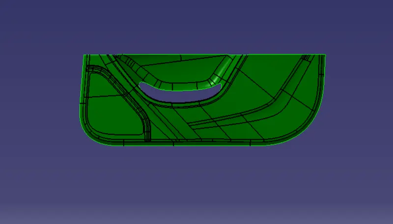
The design engineer is responsible for determining the type of surface finish required for each part or component of a product. When a Class B surface is required, the design engineer will typically choose materials and manufacturing processes that are less expensive and less time-consuming than those used for Class A surfaces. This allows for a lower-cost product to be produced, while still meeting the functional requirements and design specifications of the product.
Class C:
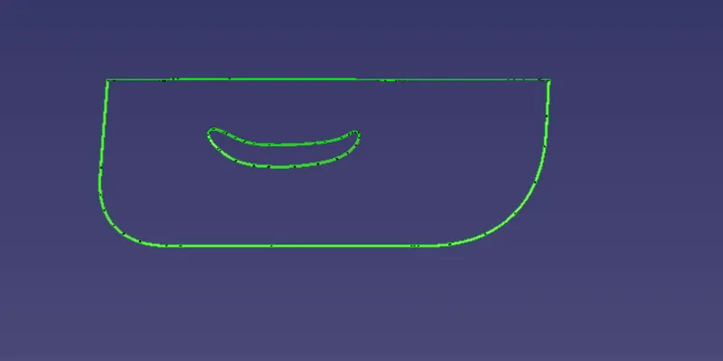
The class C surface is designed to create a join the Class A and Class C surfaces, this part can be created in Catia using the sweep command also there needs to be at least a 3-degree draft to satisfy the Draft Analysis for the manufacturing of the component.
Final Join:
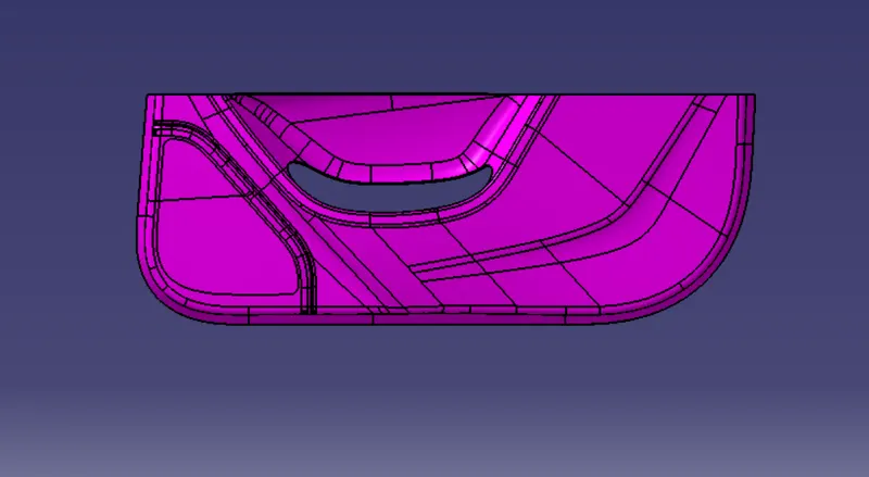
The Final Join is done by using two simple steps, Firstly, we need to join the Class A and Class C surface after that this join need to be trimmed with the Class B Surface to create the Final Join.
Closed Surface:
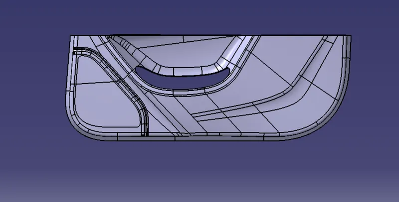
After that, we need to go to the part design workbench and using the close surface command create the base Door Trim solid part body.
Draft Analysis of Closed Surface:
In the final step, we need to do the Draft Analysis of the Solid Body to ensure the Manufacturability of the product.
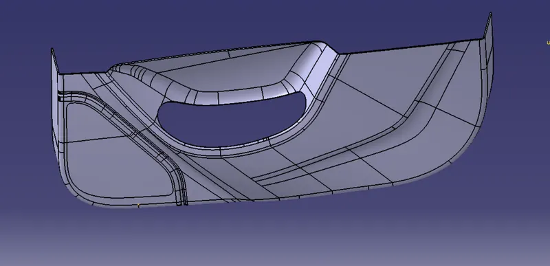
Views:
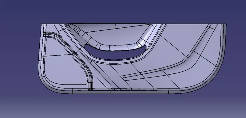
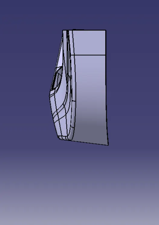
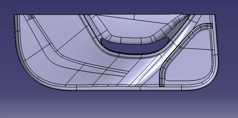
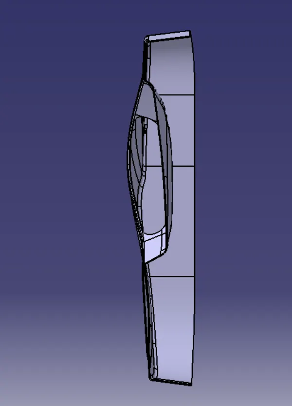
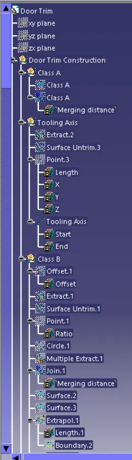
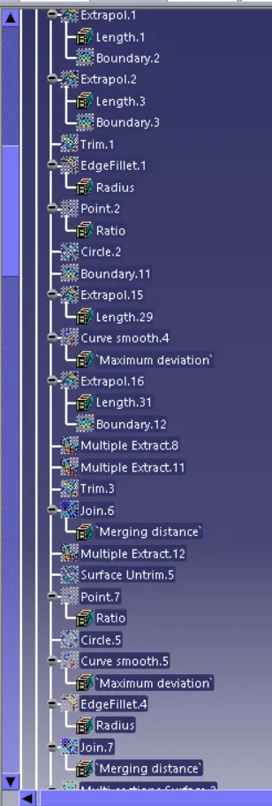
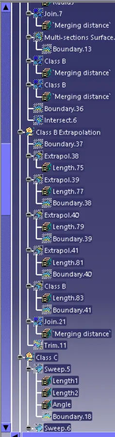
Feature Tree:
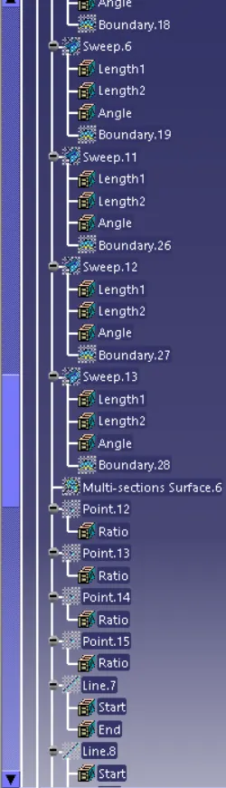
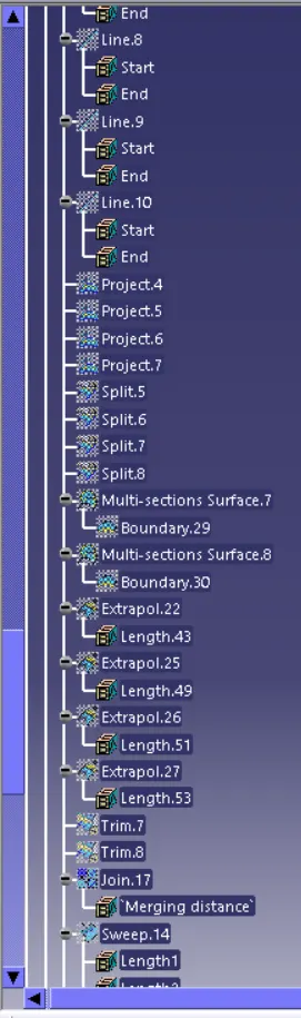
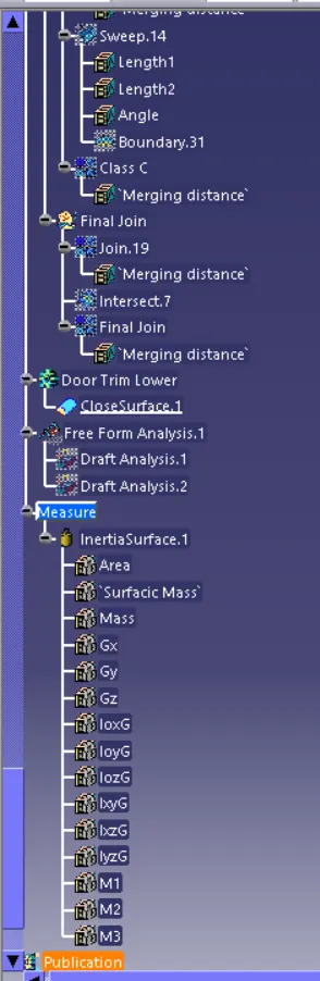
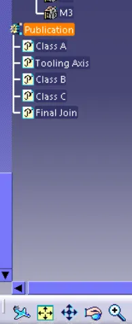
Conclusion
In this way, the Door Trim Lower design was successfully created by using the above-mentioned methods and the design also passes all the Design Considerations and Draft Analysis.