Week 10- Assembly Workbench
Assembly Workbench
Aim:
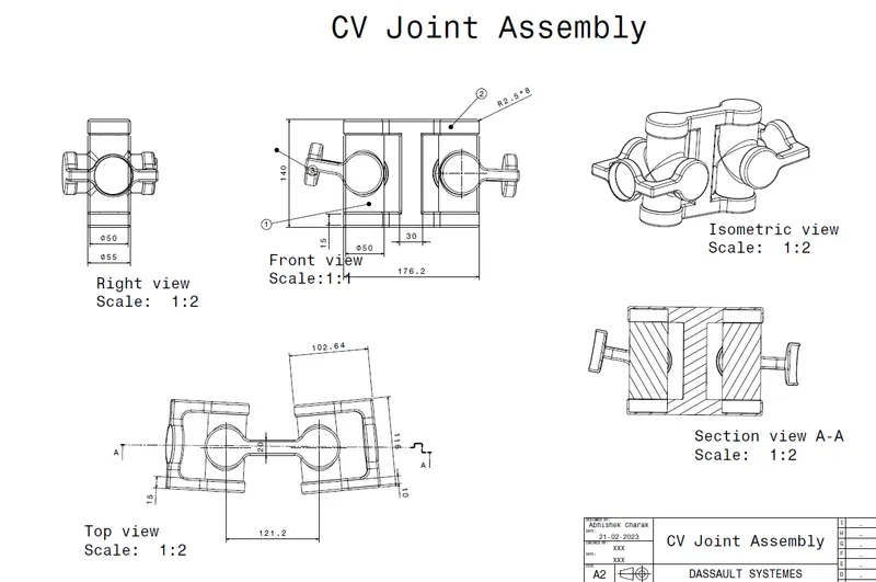
In this assignment, we will have to create 2 assemblies according to the content covered in the course. We will be provided with 2D diagrams of the components and we will have to first create the individual part files and then create a complete assembly of those part files in the assembly workbench. After creating the assembly make use of the drafting tools to create a 2D drawing similar to the one given in the assignment folder.
Objective:
- To create the various part models from the 2D drawings.
- To assemble the part models into a single component.
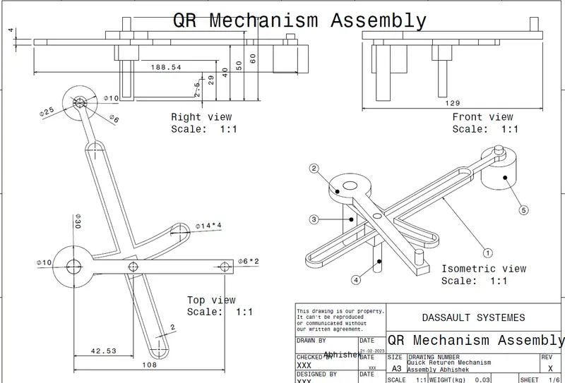
- To create the 2D drawings of the components which were created.
First Assembly:
CV Joint Mechanism:
A CV (constant velocity) joint is a type of mechanical joint that is commonly used in front-wheel drive and all-wheel drive vehicles to allow the transfer of torque from the engine to the wheels at a constant speed, while also allowing for the suspension to move up and down.
The CV joint typically comprises an outer joint, an inner joint, and a CV boot that covers the joint and keeps it lubricated. The inner joint connects to the transmission or differential, while the outer joint connects to the wheel hub.
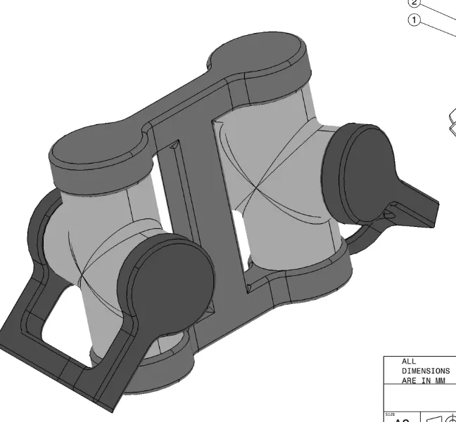
The joint itself is a ball-and-socket mechanism that allows for rotation and flexion in multiple directions, which is necessary to accommodate suspension movement and steering. This flexibility helps to prevent the joint from binding or breaking under stress and ensures that the wheels can turn smoothly.
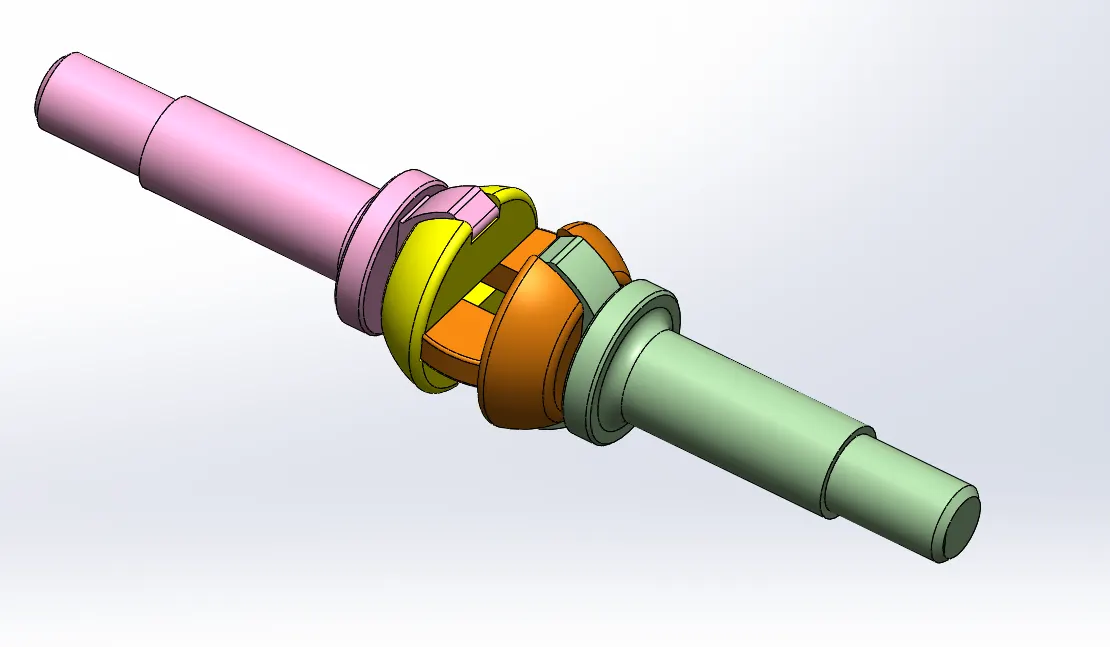
The CV joint mechanism is designed to withstand high levels of stress and wear, but it can still wear out over time due to constant movement and exposure to heat and debris. When the joint begins to fail, it can cause clicking, popping, or grinding noises when turning, as well as vibration and loss of power. In some cases, a damaged CV joint can even cause the vehicle to lose control.
Drawing:
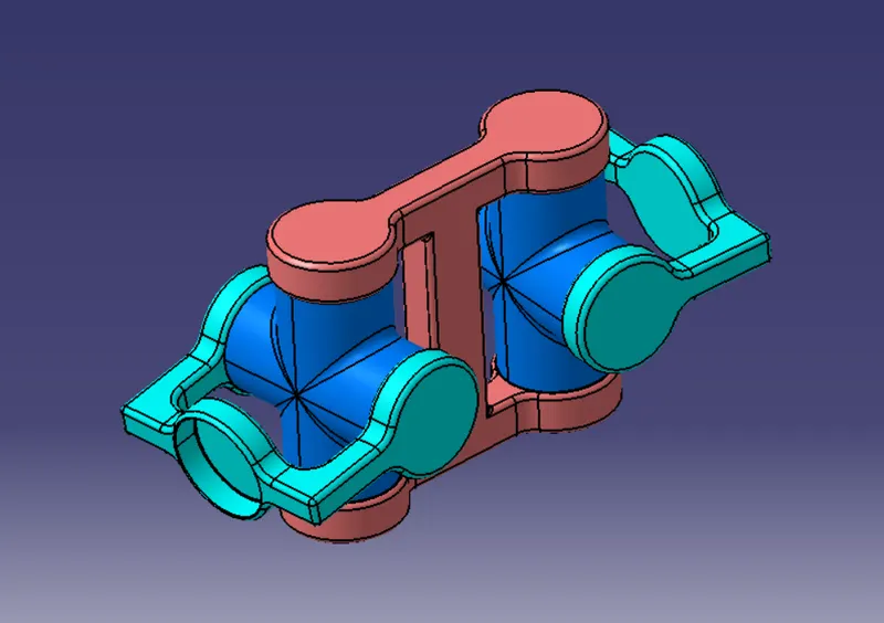
Assembly:
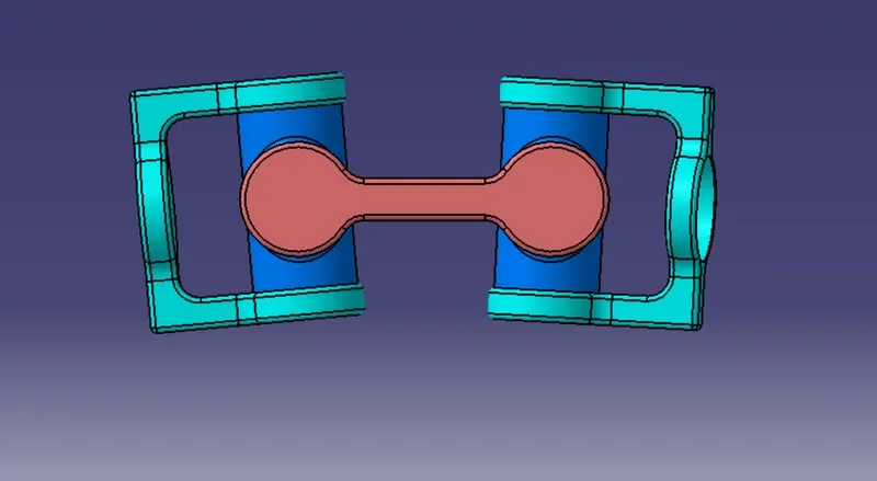
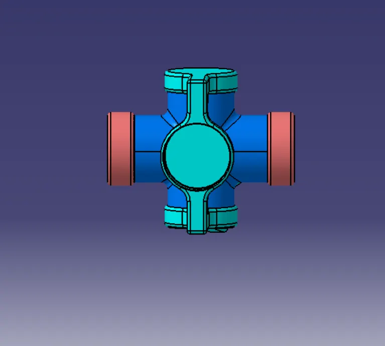
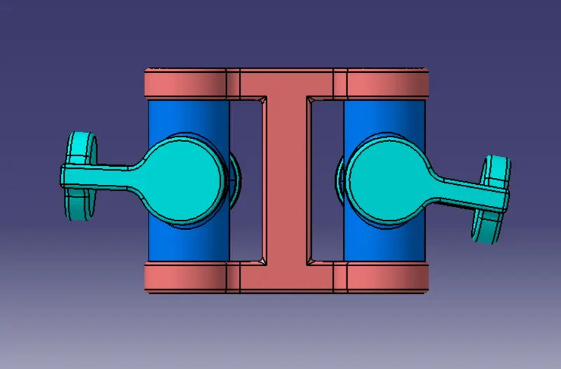
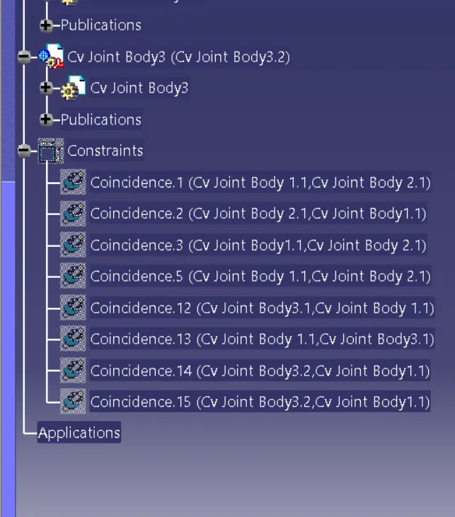
Feature Tree:
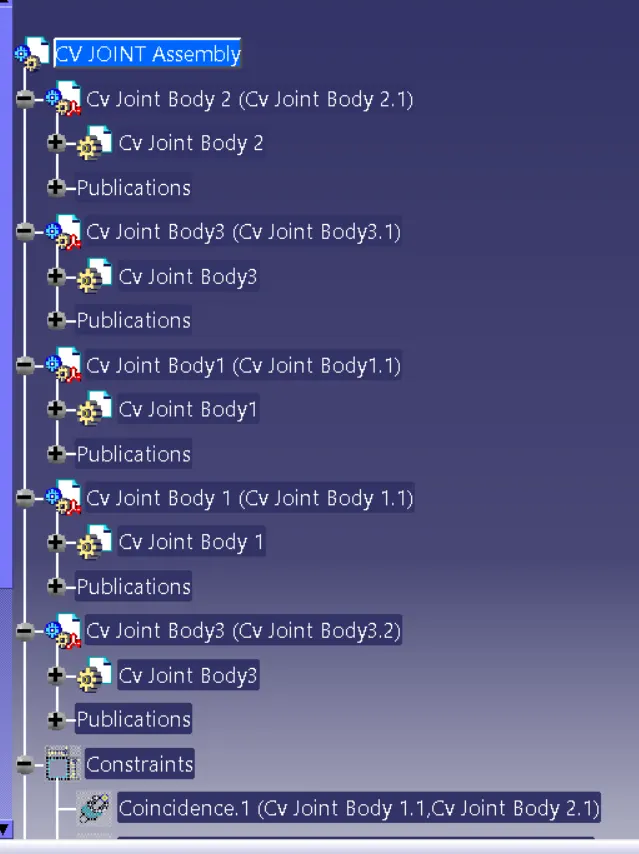
Second Assembly:
Quick Return Mechanism Assembly:
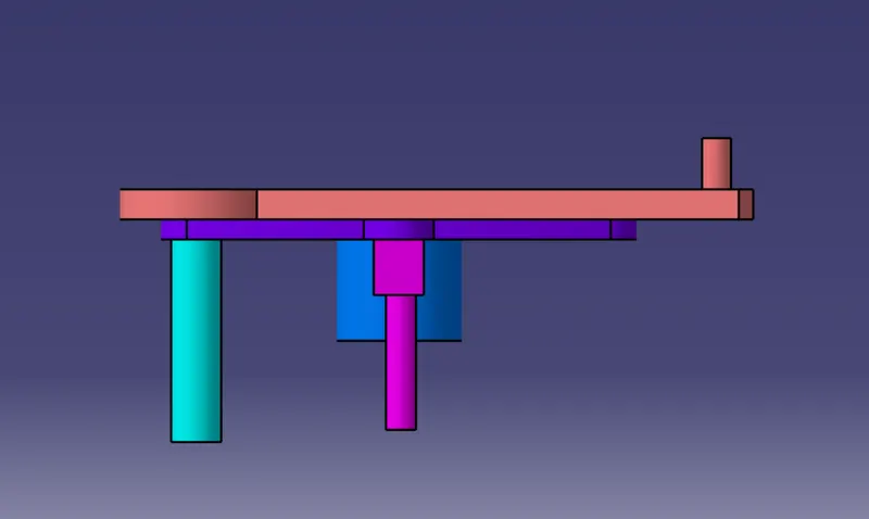
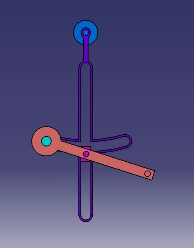
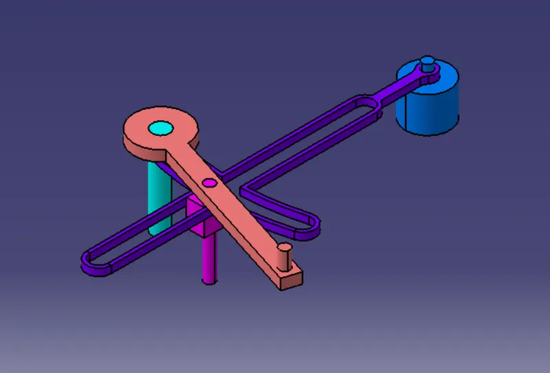
The quick return mechanism is a mechanical linkage that converts rotational motion into a reciprocating motion with a faster return stroke than a forward stroke. This mechanism is often used in machines that require a quick return motion, such as shaping machines, slotting machines, and mechanical presses. The basic design of a quick return mechanism includes a crank and a slider, with a connecting rod linking the two. When the crank is rotated, it moves the slider back and forth along a straight line. However, the return stroke of the slider is much faster than the forward stroke, due to the geometry of the mechanism.
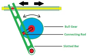
One common type of quick return mechanism is the Whitworth mechanism, which consists of a circular disc with an off-center pivot and a sliding block. As the disc rotates, the sliding block moves back and forth in a straight line, with the return stroke being much faster than the forward stroke. The quick return mechanism is useful in machines requiring a high-speed return stroke, allowing for greater efficiency and productivity. However, it is important to ensure that the mechanism is properly lubricated and maintained, as wear and tear can lead to reduced performance or even failure.
Quick Return Mechanism Assembly:
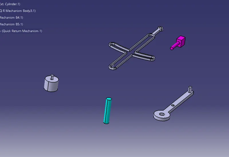
Parts:
Assembly:
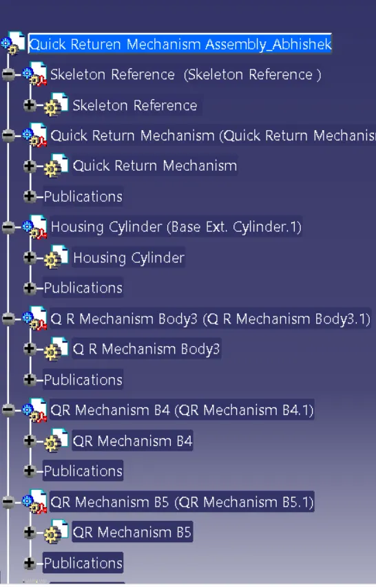
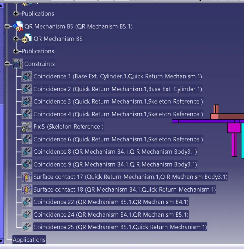
Feature Tree:
CONCLUSION :
- The part components and their respective assemblies were created using proper design consideration.
- The 2D drawings of the components were created
- All the necessary files and images were attached in the Zip files.