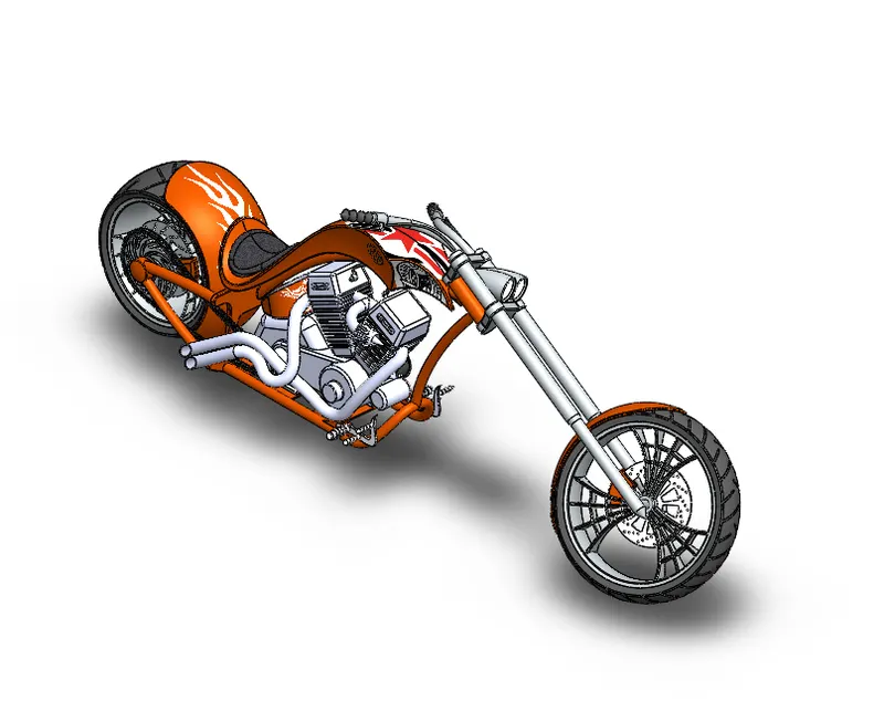
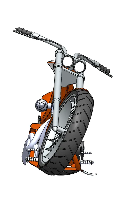
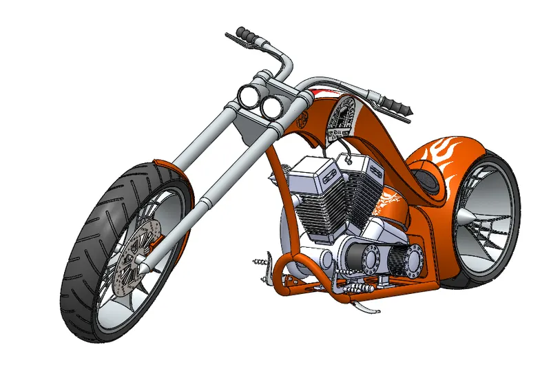
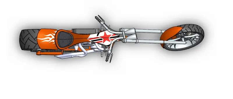
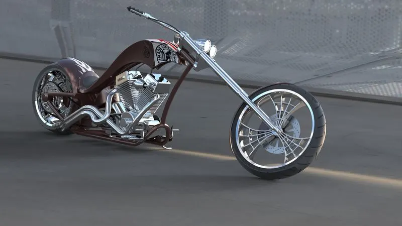
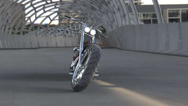
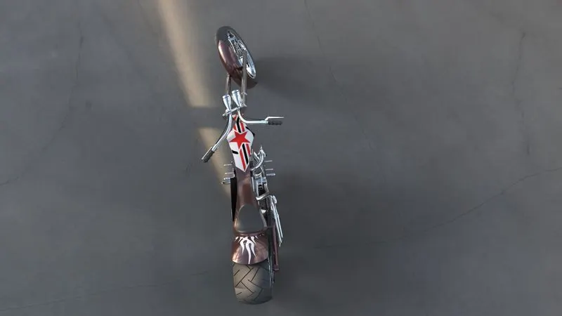
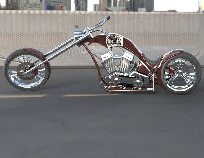
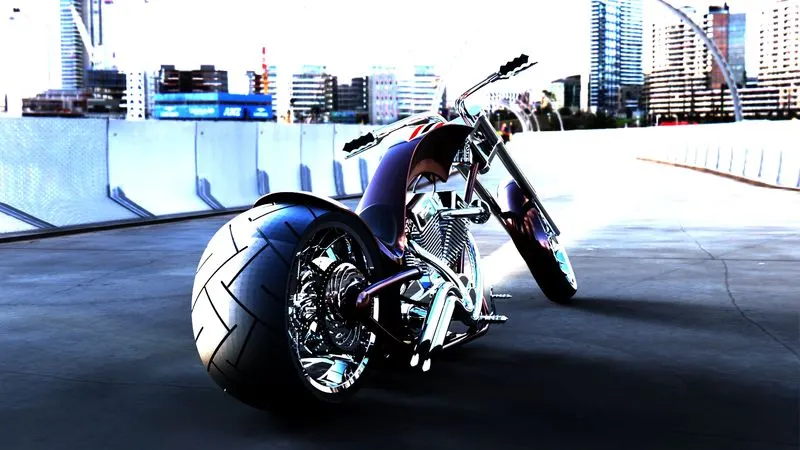
Photo Realistic Rendering
Assemble of American Chopper
Objective:
To learn the basic Interface of Solidworks and gain an understanding of different commands used in Solidworks.
Introduction:
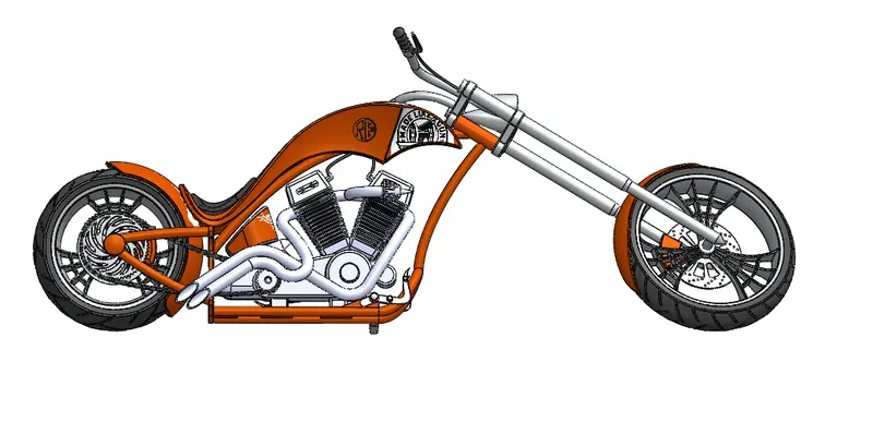
The Assemble of American Chopper is about designing a Late 60’s Retro Motorcycle parts and further assemble them to render a fully developed American Chopper.
Design Methodology:
The Designing process of the American Chopper firstly consist of Ideation > Sketching > Part Designing > Assembly > Rendering this Designing approach is further defined by the following steps.
Ideation > Sketching > Part Designing > Assembly > Rendering
Ideation-
The process of Designing the Chopper Starts with Ideation. In this process, we have to identify what kind of model are we going to design and what are the factors to keep in mind while designing.
First of all, we need to prepare a Mood Board consisting of Patterns, Colours or any pictures through which we can conceive about what we are going to design and what kinds of patterns, Colours we need to keep in mind.
Sketching-
The process of Sketching comes just after the Ideation process, in this process we take ideas from the Mood Board about what our Model should resembles. The Process of Sketching consist of various phases Firstly we have to draw a basic shape of the Chopper and after we are satisfied with the concept of the chopper then we have to prepare few more sketches based on the first sketch this provide us a window to choose the best-looking design for our further process. One can also seek advice of any other person one to choose the best design.
In the sketching part we need not to worry about the Dimensions of the Chopper, those will be taken in consideration in further processes.
Part Designing-
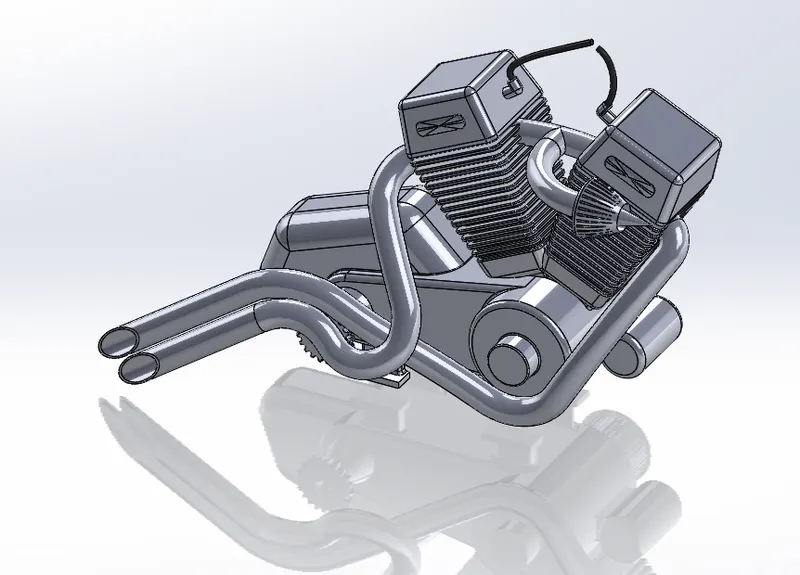
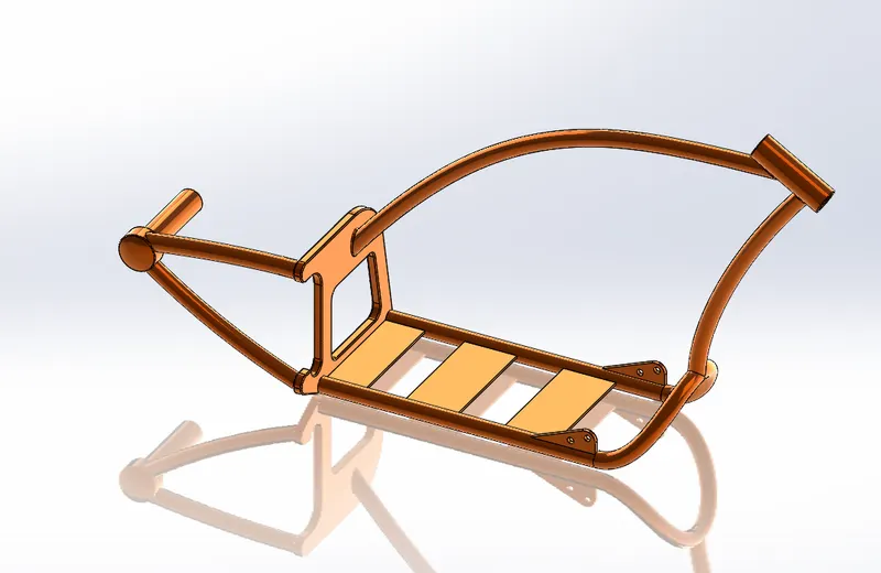
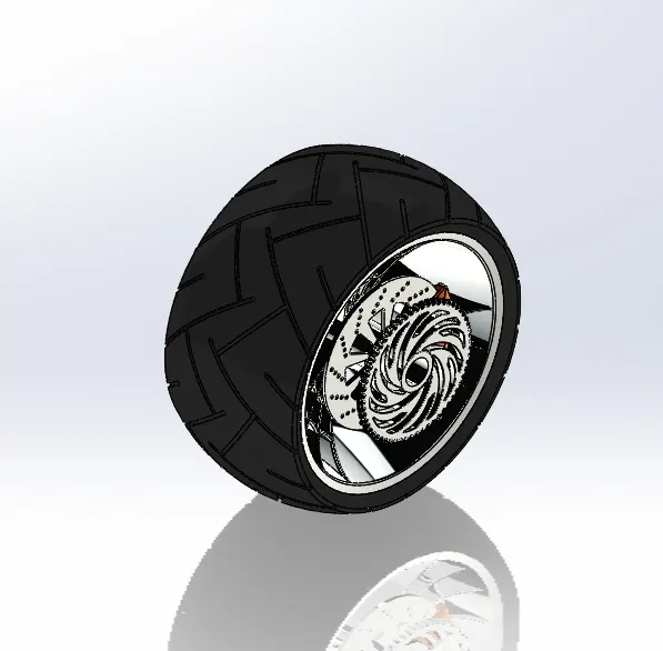
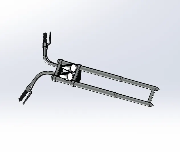
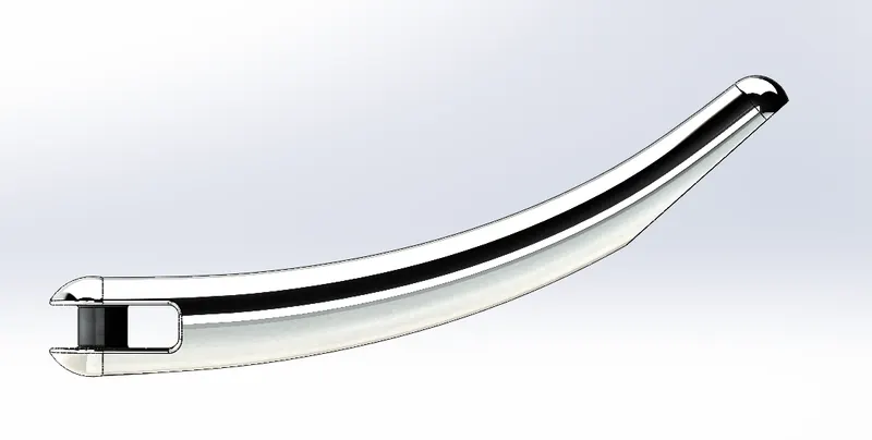
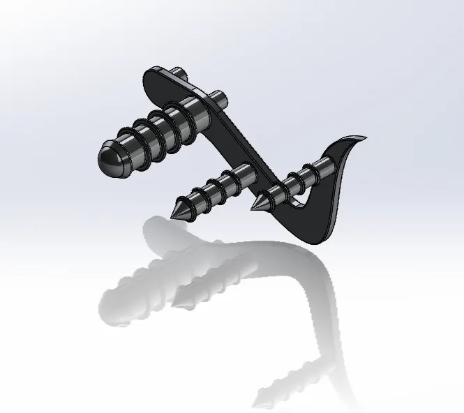
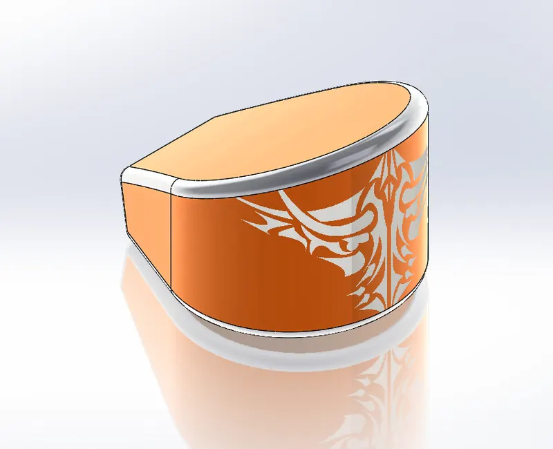
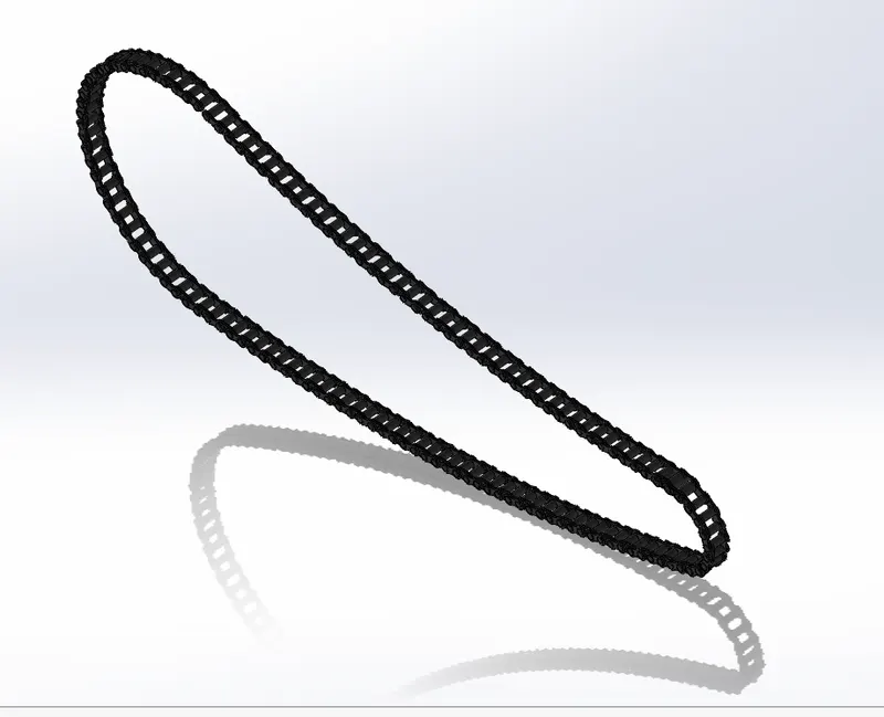
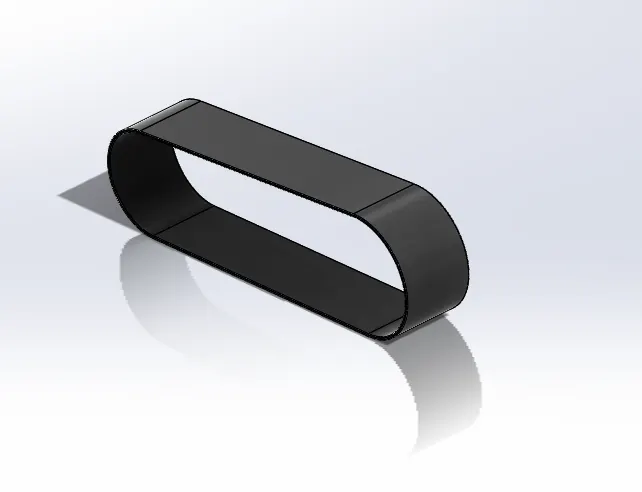
This process consists of designing various parts of the Chopper like Chain, Chassis, Engine, wheels etc successively in the Part Window of Solidworks. In this we have to be precise with the Dimensions of the parts. Also, we need to keep in mind that the sketch should always be well defined and does not have any errors.
We can also apply appearance to the parts and make them look Realistic and more Practical.
Assembly-
In the Assemble section we have to assemble different parts together with the help of Standard, Advanced & Mechanical Mates Also we need to keep in mind the dimensions and well defining the Assemble parts. We can set a Camera view further provide another perspective to view the Final Model Also, we need to make sure to apply the Appearance, Lights, Scenes and Decals to the final Assembled Product.
Visualization-
The Visualization part is totally concerned with the Appearance of the Final Product in which we need to play with the appearance, Shadows, Colours and Scenes and at last we can Render our Final Product.
Description-
In the course of Assemble of American Chopper one can familiarize about different commands of Solidworks. Some of them are as follow;
-
-
- Sketch- The Sketch command is used to start a sketch on any plane, there are many selections further in sketch like line, Circle, Spline, Rectangle, Ellipse, 3-point Arc, Polygon, Straight Slop, point etc.
- Smart Dimension- Smart Dimension is used to give dimension to any sketch in order to fully define that sketch.
- Trim Entity- Trims open sketch entities outside of two bounding entities. Trimming with Trim to Closest. Trimming a 3D Sketch. Trim Property Manager. You can use the Trim Property Manager to select a trim type and control other trimming options.
-
-
-
- Convert Entity- You can create one or more curves in a sketch by projecting an edge, loop, face, curve, or external sketch contour, set of edges, or set of sketch curves onto the sketch plane.
- Offset Entity- Offset entities takes a copy of your existing geometry and copies it at an offset. Instead of recreating geometry, you can use this to quickly sketch based on model geometry. Offset entities is a great tool for enlarging or shrinking your sketch geometry.
- Extrude- You can create extruded surfaces from models that include 2D or 3D faces and knit the extruded surfaces to surrounding features. Click Insert > Surface > Extrude. Select a face: To extrude from a 3D face, select a 3D face.
- Extrude Cut- You create an extruded cut in a two-dimensional or axisymmetric planar part by sketching the two-dimensional cross-section of the cut directly on the plane of the part. The cut always passes completely through the part.
- Loft- Loft creates a feature by making transitions between profiles. A loft can be a base, boss, cut, or surface. You create a loft using two or more profiles. Only the first, last, or first and last profiles can be points.
- Fillet- Fillet/Round creates a rounded internal or external face on the part. You can fillet all edges of a face, selected sets of faces, selected edges, or edge loops.
- Chamfer- The chamfer tool creates a bevelled feature on selected edges, faces, or a vertex. To create a chamfer: Click Chamfer. on the Features toolbar, or click Insert > Features > Chamfer.
-
f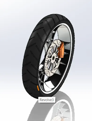
Conclusion-
In this Assembly of American Chopper, the main objective was to perceive different commands and interface of the Solidworks which in my case more than enough to be familiar with the commands & interface. So, while Designing the American Chopper we come to know about how the solidworks interface works and also how to use different commands.