Roof Design
ROOF DESIGN
AIM:
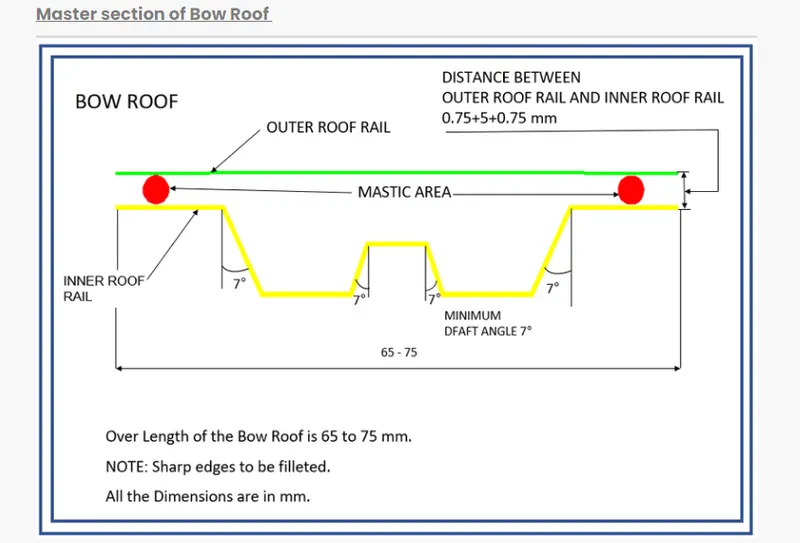
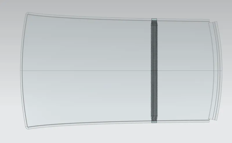
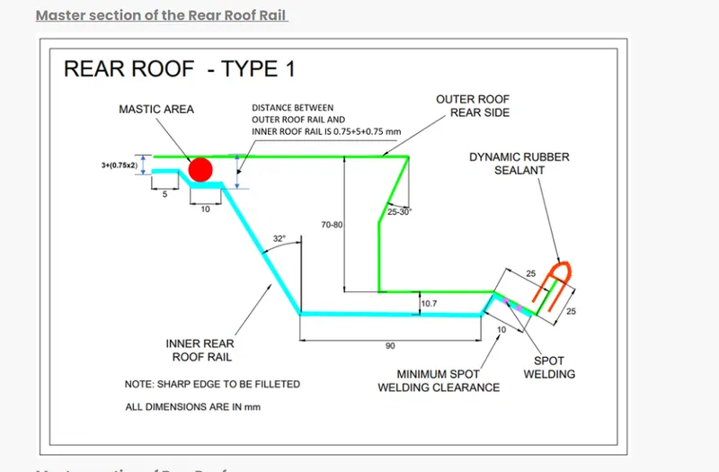
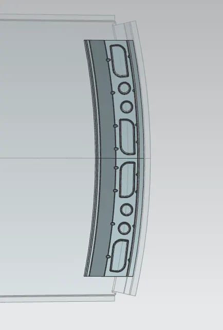
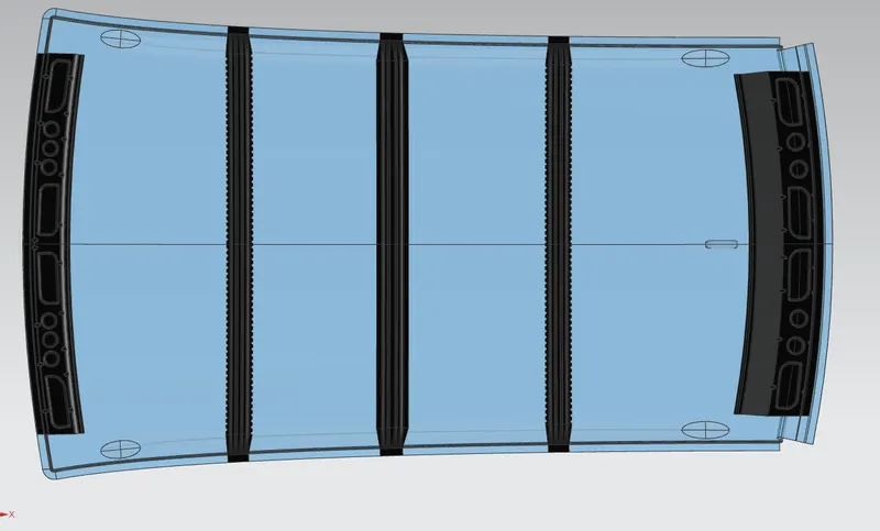
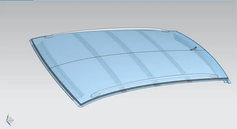
To design the Roof Assembly with all the components like Front Roof Rail, Rear Roof Rail, Bow Roof Rails, and Center Roof Rail by the provided master sections and to consider all the design requirements and criteria like Heat Distortion and Snowed Criteria as per the OEM standards.
Roof:
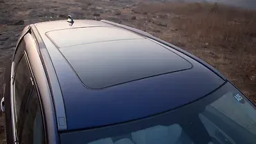
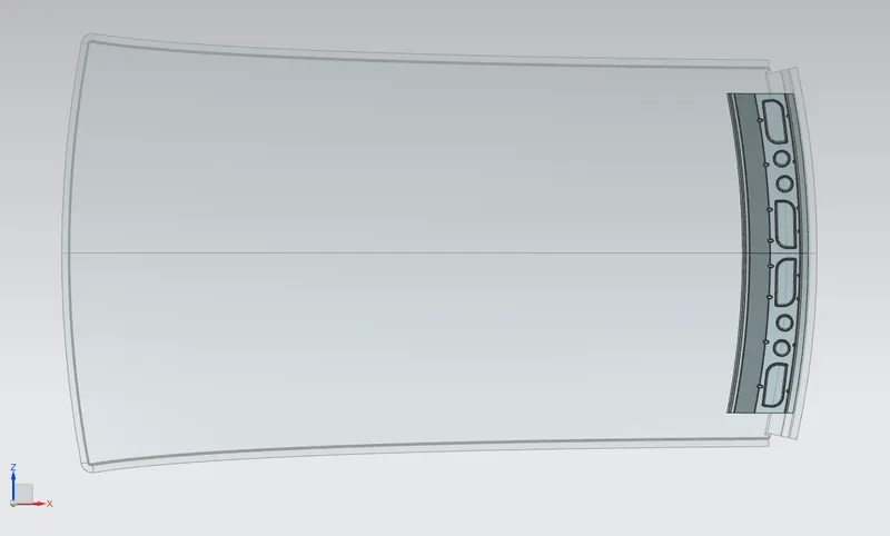
An automobile roof or car top is the portion of an automobile that sits above the passenger compartment, protecting the occupants from sun, wind, rain, and other external elements. Because the earliest cars were designed in an era of horse-drawn carriages, early automobile roofs used similar materials and designs.
OBJECTIVE
- Designing a Roof with all the necessary reinforcements
- Performing a curvature study on the roof by considering Heat Distortion and Snow load criteria as per Industry Standards.
- Calculate the moment of inertia for the reinforcements.
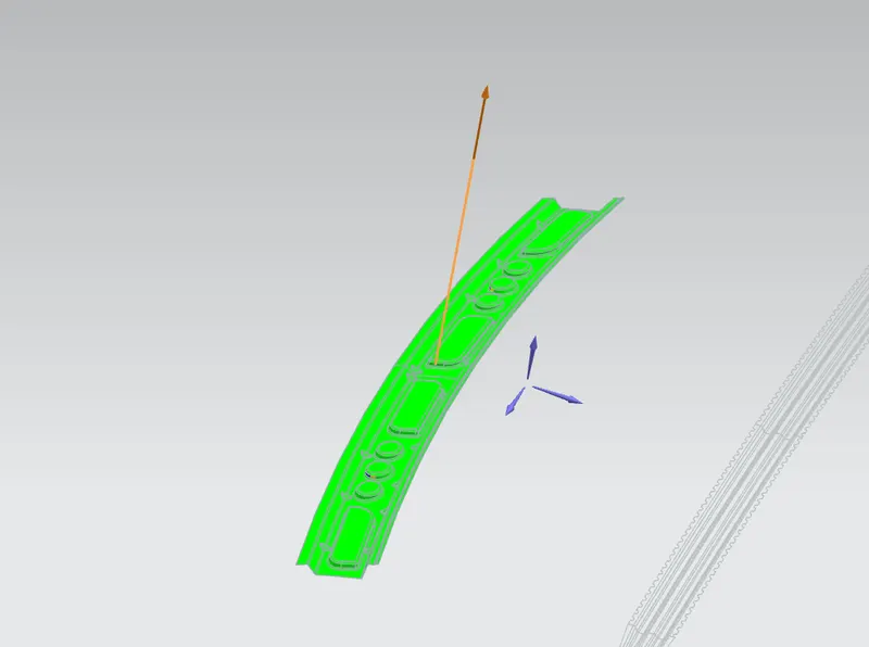
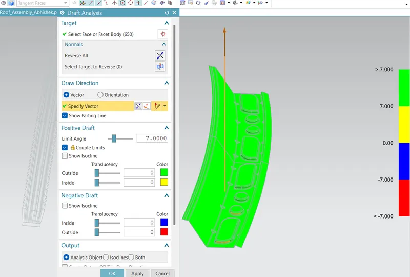
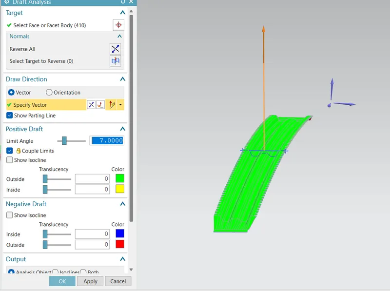
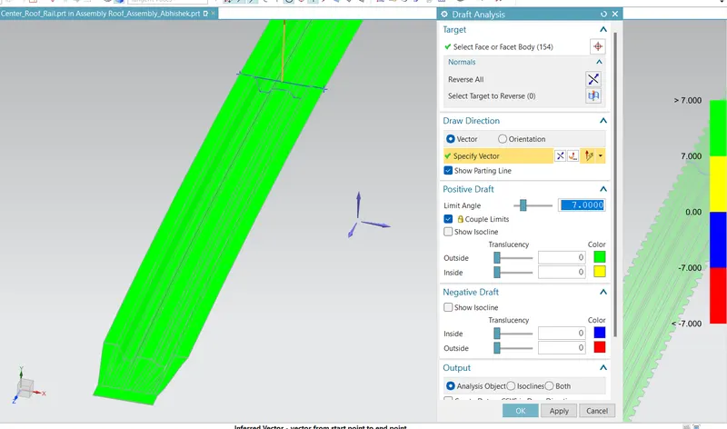
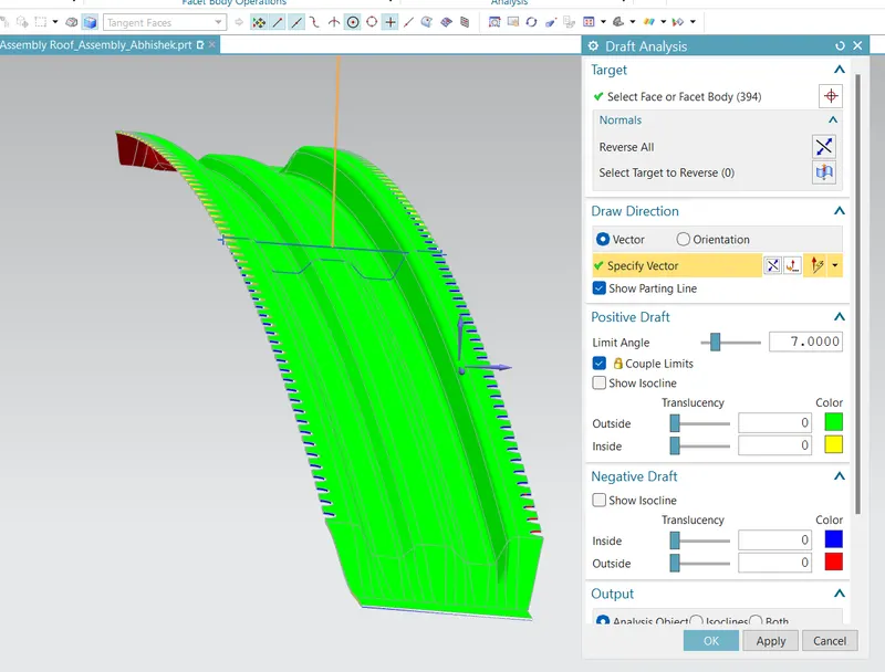
- Perform the draft analysis for analyzing the component's manufacturing feasibility.
Front Roof Rail:
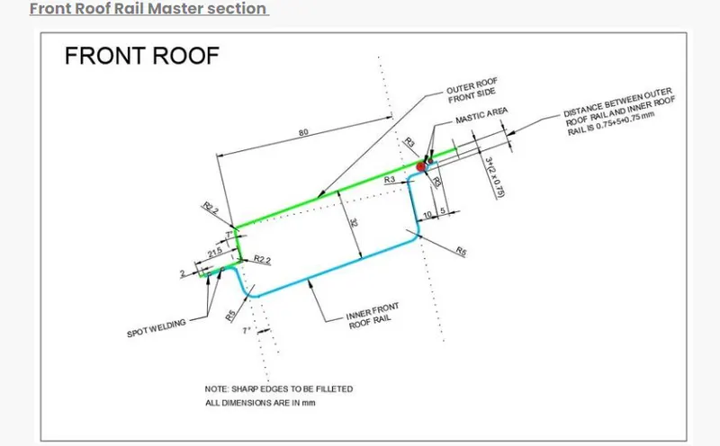
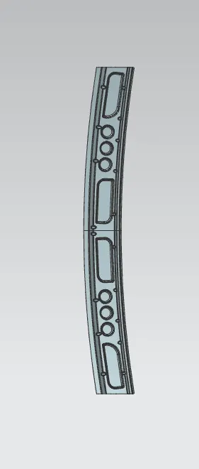
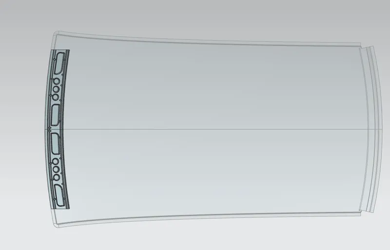
The Front Roof Rail is developed using the Master Section and the Styling Surface using different commands like Offset Surface, Law Extension, Studio Surface, Face blend, Edge Blend, and at the end in order to increase the strength of the part we also added some Emboss and Darts to the part.
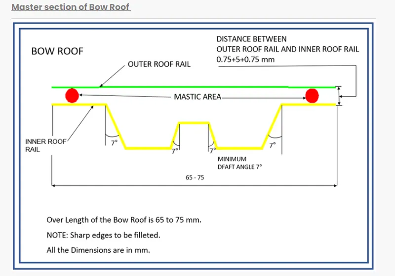
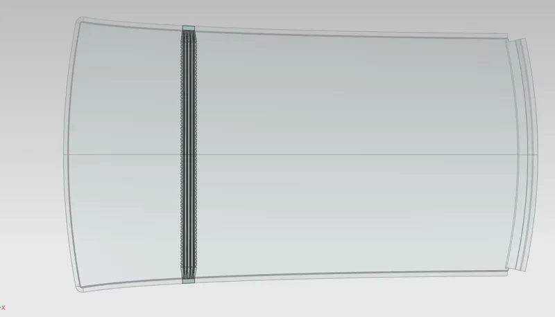
Bow Roof:
Center Roof Rail:
Bow Roof 2:
Rear Roof Rail:
| Bow | Rx | Ry | R | I | L | t | R2/t | W | Remarks |
| FR-1st | 2633.30 | 5705.50 | 3603.46 | 414.20 | 2033.70 | 0.75 | 17313231.96 | 1.614 | OK |
| 1st-CTR | 5055.83 | 6057.87 | 5481.83 | 330.28 | 2033.70 | 0.75 | 40067280.19 | 1.93 | OK |
|
CTR-2nd |
9615.36 | 4171.34 | 5818.49 | 365.13 | 2033.70 | 0.75 | 45139767.84 | 2.06 | OK |
| 2nd-RR | 3376.86 | 13954.92 | 5437.85 | 471.95 | 2033.70 | 0.75 | 29570212.62 | 1.89 | OK |
According to the table, no value of w is less than 3.1 which indicates that the current bow row alignment is in a satisfactory state and judged to be acceptable.
Snowed Load Criteria-
Snow Load Prediction Formula
Qr = [Iy x t2] / [α x s x [(Rx + Ry)/2]2 x 10-8]
Note: The Qr value given over here is correct. There was a typo error in the formula given in the video.
Where,
α = My x Lx2 x 10-12 , My = Y(Ly-Y)
t = Roof plate thickness [mm]
Ly = Distance between the front and rear roof Rails on the Vehicle along with 0Y[mm]
Length of Roof panel with the center point between Roof rail Front /Rear as the front and rear reference point.
Lx = Distance between the Left and Right end of the roof on the Roof BOW [mm]
The width of the roof panel is exposed on the surface.
Y = Distance front Front Roof Rail to Roof BOW[mm]
s = Distance for which Roof BOW bears divided load [mm]
s = L1/2 + L2/2
Iy = Geometrical moment of inertia of Roof BOW (Y cross-section )[mm4]
Rx = Lateral direction curvature radius of roof panel Y cross-section on Roof BOW [mm]
Roof panel curvature Radius of the Length Lx in Front view
Ry = Longitudinal Direction curvature radius of the Roof panel X cross-section on Roof BOW [mm]
Roof panel X curvature radius of length s in Side view
Judgment condition
Qr ≥ 3.1
250 ≤ s ≤ 380
Section Inertia Calculations
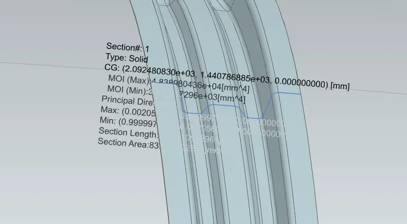
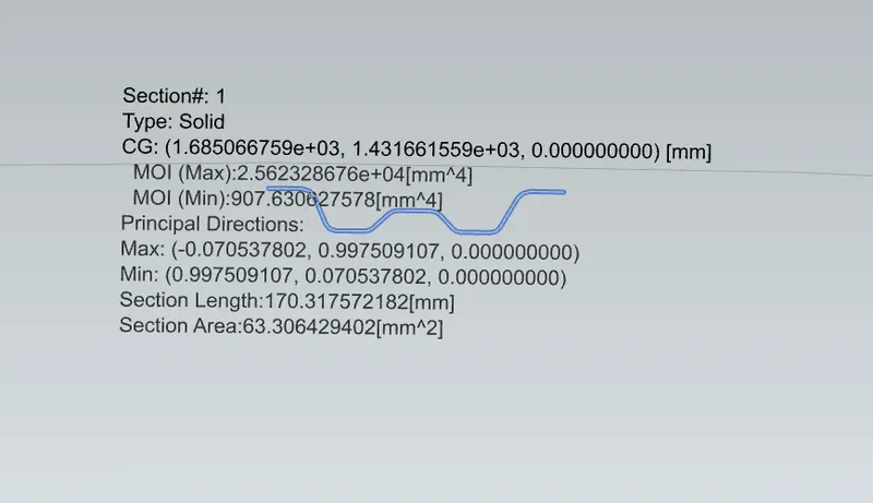
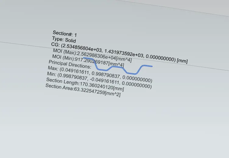
The section moment of inertia is used to anticipate how much a component will deflect. A larger moment of inertia is preferred since it minimizes deflection for a given force. The inclusion of flanges and embosses, as well as the thickness of the component, enhances the section inertia of the part. The master sections of the roof and roof rails, as well as their section analysis, are provided here.
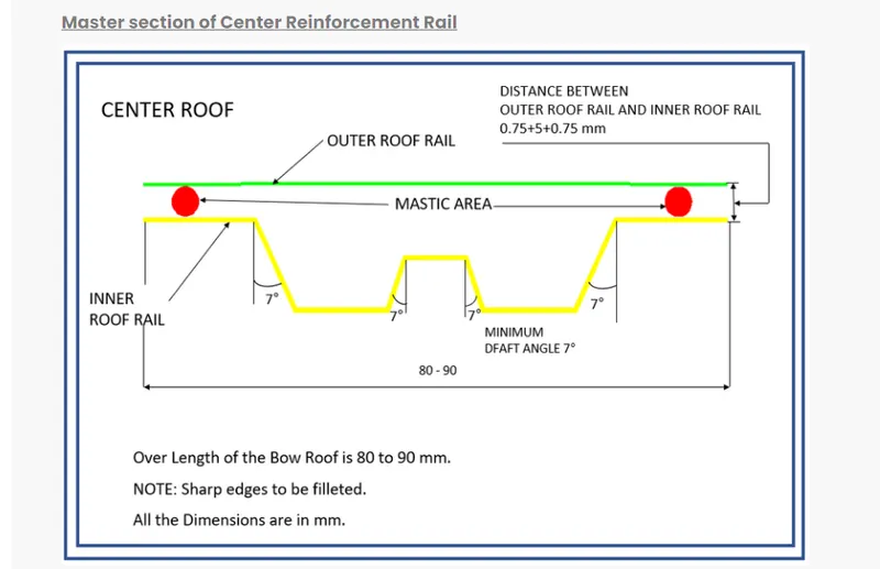
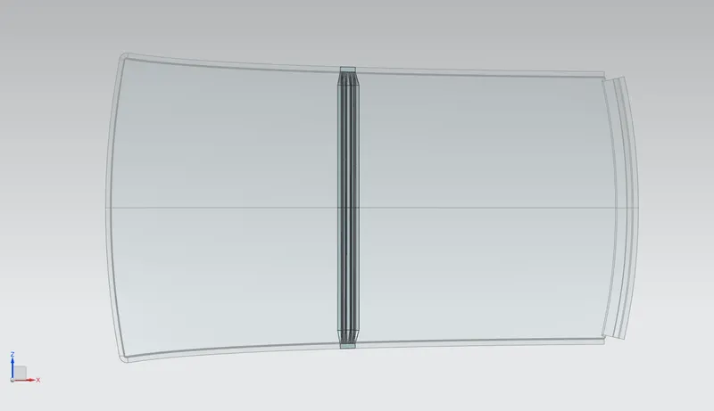
Moment of Inertia for Centre Roof Rail:
Moment of Inertia for Bow Roof 1:
Moment of Inertia for Bow Roof 2:
| Bow | Iy | a | Ly | Lx | y | s | Rx | Ry | t | Qr | Determination |
| FR-1st | 907.63 | 0.993 | 2033.70 | 1135.52 | 503.63 | 205 | 6851.89 | 3256.53 | 0.75 | 22.22 | OK |
|
1st- CTR |
3.11 | 0.792 | 2033.70 | 1086.93 | 407.53 | 222.21 |
8621.25 |
5962.59 | 0.75 | 12.22 | OK |
| CTR-2nd | 917.29 | 0.782 | 2033.70 | 1061.07 | 442.59 | 306.9 | 4182.05 | 10046.33 | 0.75 | 9.41 | OK |
| 2nd-RR | 2033.70 | 1044.35 | 612.36 | NA | 3166.48 | 4677.17 | 0.75 | NA |
According to the table, no value of w is less than 3.1 which indicates that the current bow row alignment is in a satisfactory state and judged to be acceptable.
Draft Analysis:
The Draft Analysis allows the user to easily analyze a part for a proper draft angle. A Draft Angle describes the amount of taper for molded or cast parts perpendicular to the parting line. Find the Draft Analysis in the Tools tab. Draft Analysis is applicable for 3D part models.
Draft Analysis of Front Roof Rail:
Draft Analysis of Rear Roof Rail:
Draft Analysis of Bow Roof 1:
Draft Analysis of Centre Roof Rail:
Draft Analysis is Bow Roof 2:
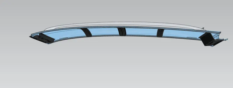
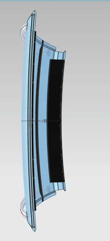
BOW ROOF IMAGES:
CONCLUSION
Thus the roof is designed with all the necessary reinforcements and roof rails according to the given master section and the styling surface, by considering all the design parameters. Also, the curvature study is done by taking the heat distortion and snow load criteria for determining the strength of the roof.