Week 8 - Challenge 3 - Coin Holder Design
Objective-
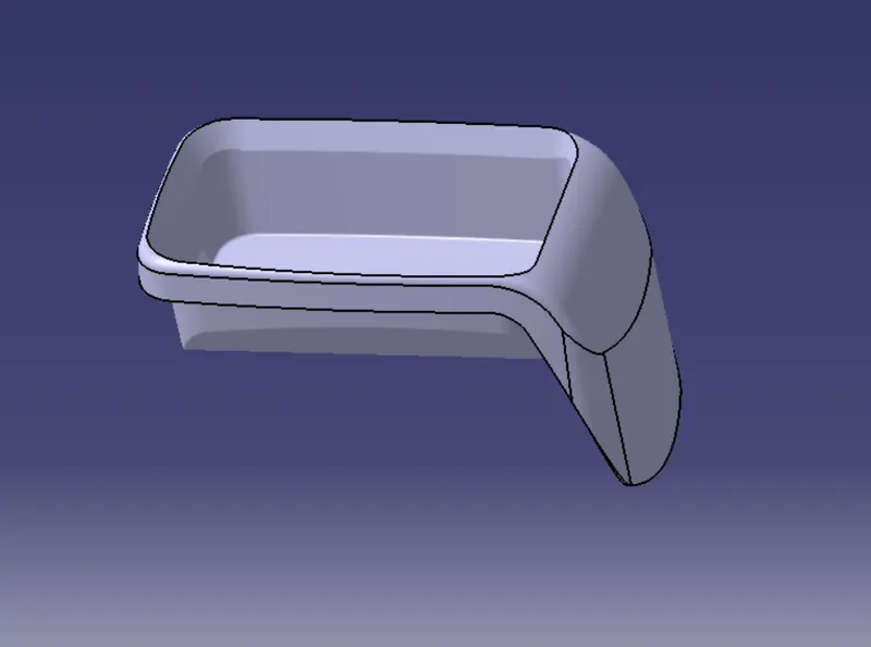
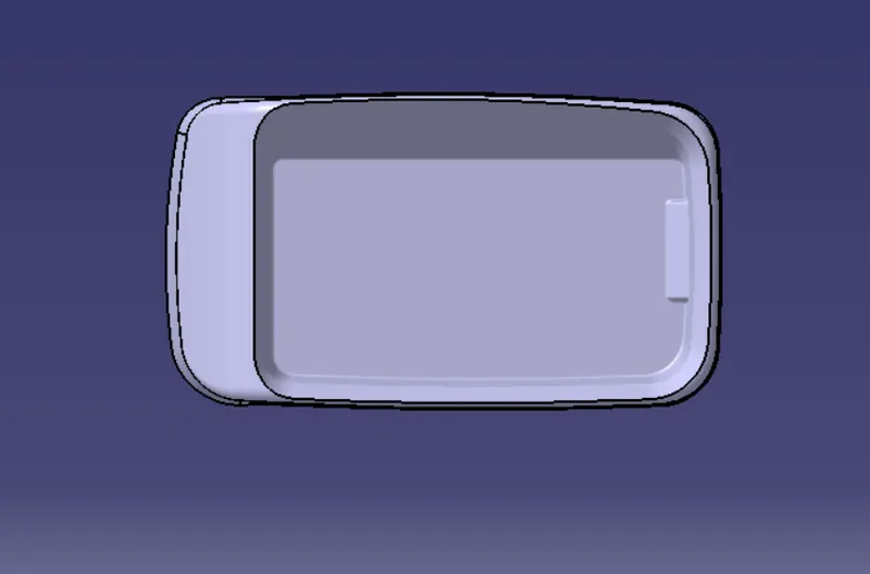
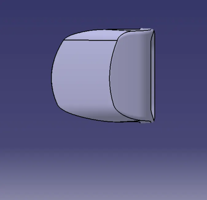
To create the Coin Holder Plastic component through the given Class-A surface. To begin with, the tooling axis for the given Class-A Surface should be created to meet the draft angle requirements and perform the draft analysis on the model at the end. Take the Thickness of the component to be 2.5 mm.
Class A Surface-
Class A Surface represents the aesthetic look of the model and is provided by the styling team. Since we are the product designers, we are not the best people to modify the Class A Surface until it's important or something in Class A does not meet the manufacturability requirements. A minor tweak can be made to the Class A surface after consulting with the styling team. In general, the Class A surface represents the component's outermost surface.
Class B Surface-
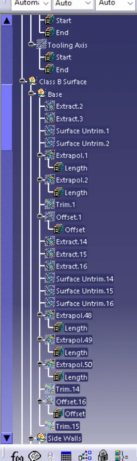
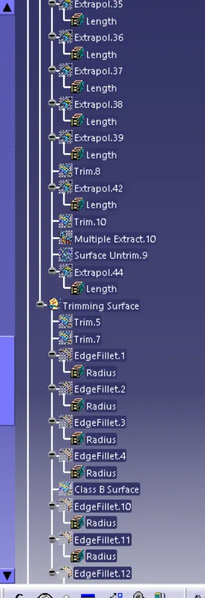
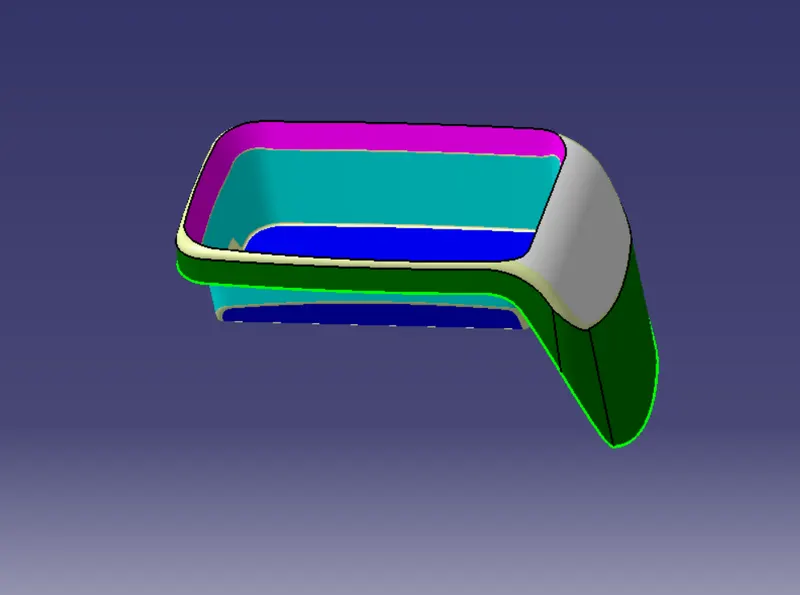
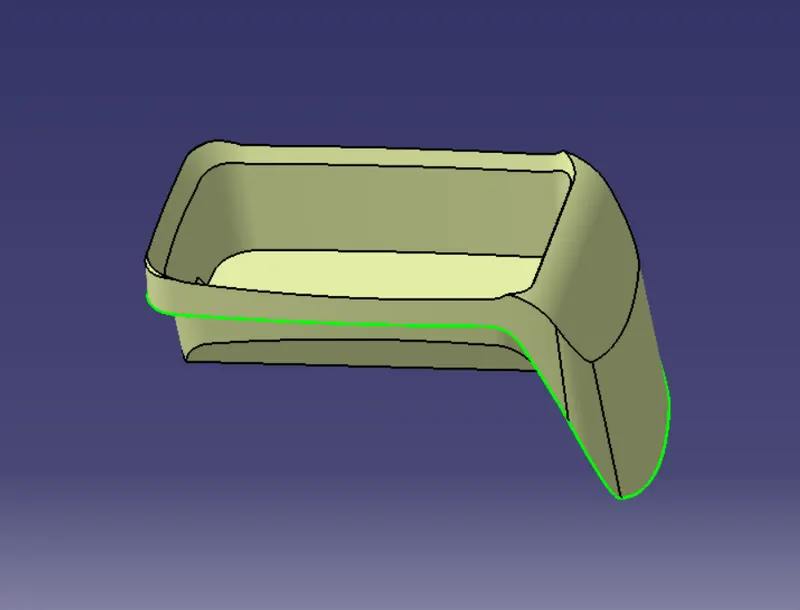
The Class B Surface represents the offset Surface of Class A, It shows the thickness of the component. The creation of this surface involves the use of various commands like Extrude, Untrim, Extrapolate, Trim and Offset.
Class C Surface-
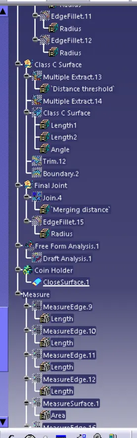
Class C Surface represents a join between the Class A and Class B surface For creating a class C surface, involves commands like Extract and Sweep.
Tooling Axis-
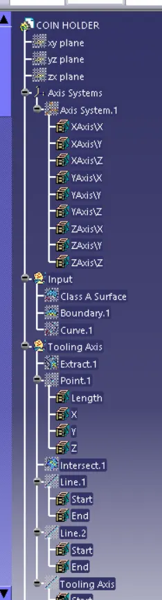
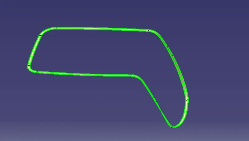
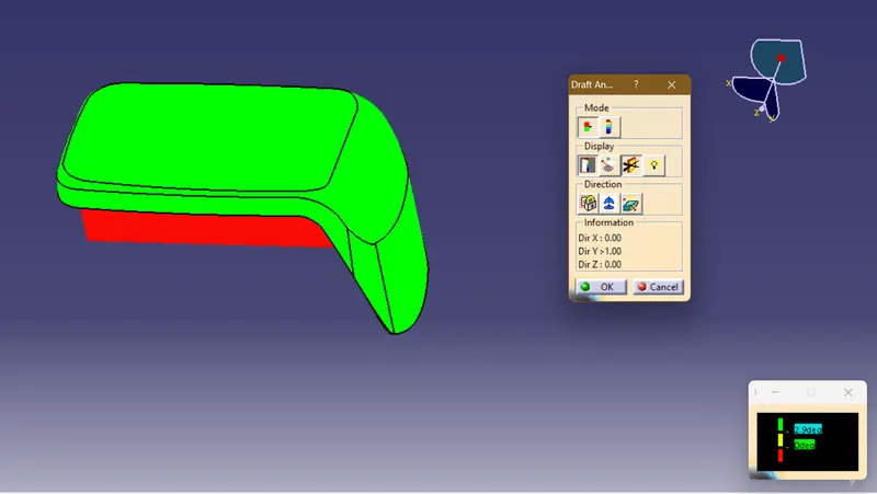
The Tooling Direction determines the direction in which the mold pulls apart. The mold is built in two separate pieces, basically. You have a Cavity side and you have the Core side. The Core pulls apart from the Cavity and that's the Dyeline or the Tooling Direction. We have to check visually all three Tooling Axis. The best possible tooling axis is along the Z axis. After creating the tooling axis, we have to look for a Draft Analysis. In Catia V5, there is a tool for Draft Analysis.
Bisecting Method-
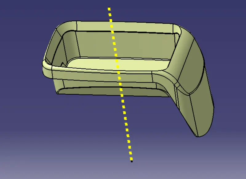
With the bisecting method, you find the proper tooling axis by using the dummy tooling axis. The bisecting method uses a bisecting line that either bisects the two lines or shows an error that indicates they are parallel. Using the bisecting line option, we bisect the line to create a line at the midpoint of the two lines to determine whether the surface is a tool able or not. By using the bisecting line option in the line command, we create a tooling clearing axis for x and y, which will be used to create the main tooling axis.
Drafting-
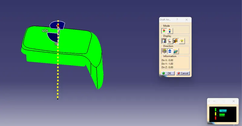
The Draft Analysis allows the user to easily analyze a part for a proper draft angle. A Draft Angle describes the amount of taper for molded or cast parts perpendicular to the parting line.
Model-
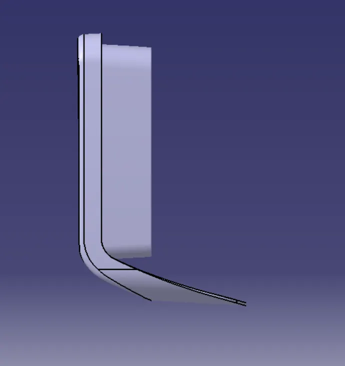
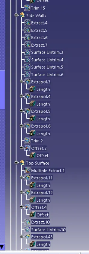
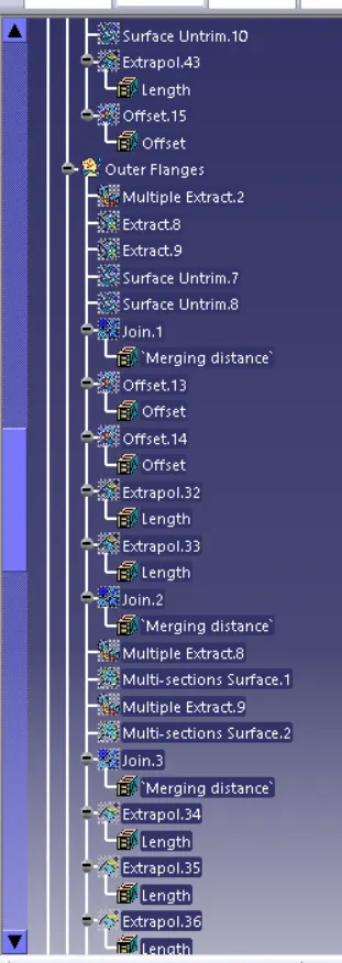
Tree Structure-