Week 8-3D Tetra Meshing Challenge

Introduction
In geometry, a tetrahedron (plural: tetrahedra or tetrahedrons), also known as a triangular pyramid, is a polyhedron composed of four triangular faces, six straight edges, and four vertex corners. The tetrahedron is the simplest of all the ordinary convex polyhedra and the only one that has fewer than 5 faces.
In Meshing, s 3D tetra first order element is made of 4 tria faces and 4 nodes as shown in below image.
Main quality to be checked for tetra element is its height. A tetra element has four nodes and hence four heights from each node to its opposite face.
Tet Collapse / Tetra Collapse:
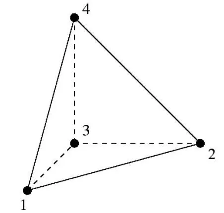
At each of the four nodes of the tetra, the distance from the node to the opposite side of the element is divided by the square root of the area of the opposite side. The minimum value found is normalized by dividing it by 1.24, and then reported. As the tetra collapses, this value approaches 0.0. For a perfect tetra, this value is 1.0.
_____________________________________________________________________________________________________________________
Objective
Here we will see the creation of Tetra mesh with different ways of creation on different models and how to debug get required quality of Tetra Mesh.
There are three ways to crate Tetra Mesh in HyperMesh as given below:
- Create 2D tria mesh and convert into 3D Tetra Mesh
- Create Tetra Mesh using “Volume Tetra” option under 3D panel
- Create Tetra Mesh using “Quick Tetra” under Utility Tab
_____________________________________________________________________________________________________________________
Procedure:
(1) Tetra Mesh Generation Method: 2D to 3D conversion
Criteria:
- Target Element Size: 5 Units
- Element Size: 2 Units
- Element Sixe: 7 Units
- Tet Collapse: 0.15
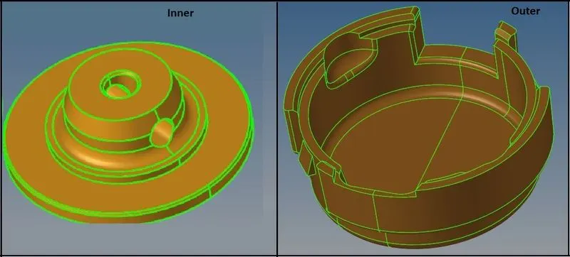
- There are two models here as shown in above image as Inner and Outer.
- Perform cleanup operations on both models one by one.
Inner:
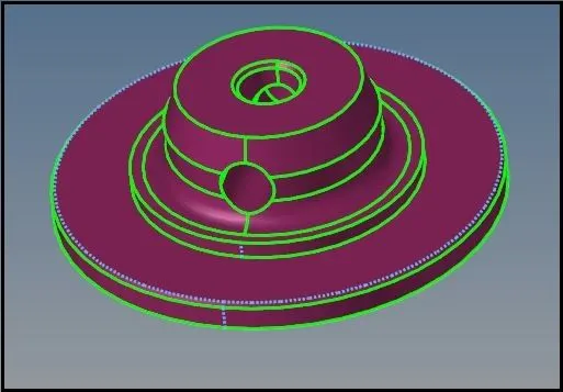
- Remove or toggle extra edges from the models.
- Remove chamfers or fillets which can lead to minimum size elements as shown in above image.
- Create 2D Mesh on the surface of the model with only tria elements.
- Make sure the Target Elements Size = 5 units, Min = 2 units and Max = 7 Units.
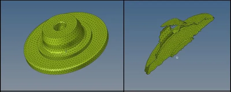
- As we can see 2D Tria Mesh is created with help of AutoMesh.
- Also by masking some elements, we can see the Mesh is 2D.
- Check if there is minimum or maximum length elements are present or not.
- After correction in quality of 2D Mesh, we can create 3D Mesh.
- Now go to 3D > Tetra Mesh > Select all Elements > Mesh.
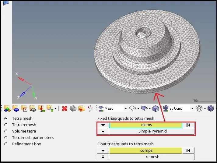
- Here for selection of elements, keep “Simple Pyramids”.
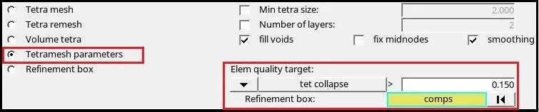
- Here in Tetramesh Parameters keep tet collapse = 0.150.
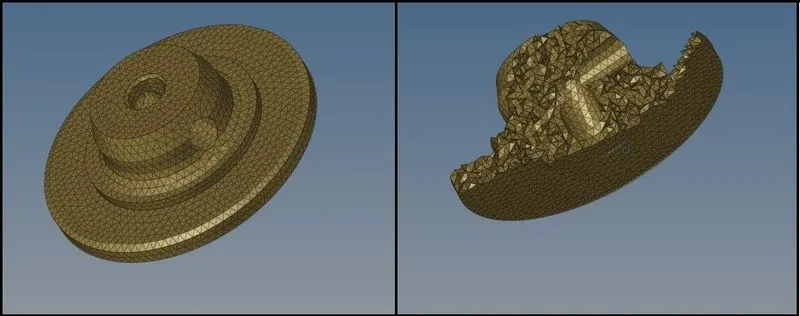
- As in above image, 3D Tetra Mesh is created. By masking elements we can check the 3D Mesh generation.
- Now go to Tools > Check Elements> Tet Collapse
- Here give Tet collapse = 0.15 and check for failing elements.
- If there are failed elements, then select “Save Failed”.

- Now select Tools > Mask > Elements > Retrieve > Mask > Reverse.
- By above procedure, we can separate the failed elements as below:
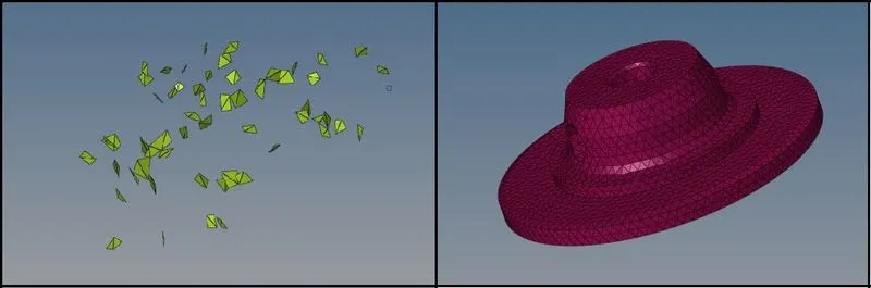
- As we can see in above image, after separating the failed elements, we can easily work on it and remove errors and make the elements better for quality.
- Repeat the process of masking the failed elements and making correction in mesh till there are no elements failing for tet collapse.
Outer:
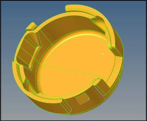
- As per above procedure create 2D Tria mesh for the outer model.
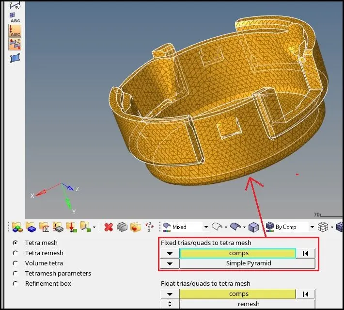
- Here we can see in above image, that instead of elements, we can also select “Components” to crete 3D Tetra mesh from 2D.
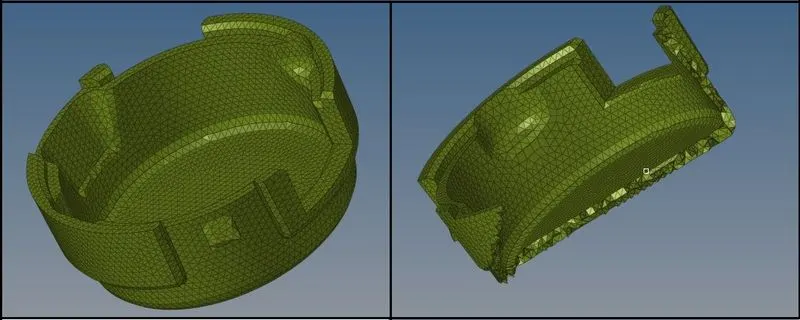
- Always check if the 3D Tetra Mesh is generated properly or not by masking some elements.
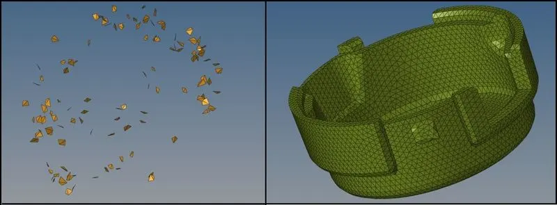
- Here we can do same procedure to eliminate tet collapse in the model and create good Tetra Mesh model.
- Thus we can create easily 3D Tetra Mesh from 2D Tria Mesh very effectively and by this method, we can get less failed elements, which can help to correct tet collapse faster and we can create good quality 3D Mesh.
_ _ _ _ _ _ _ _ _ _ _ _ _ _ _ _ _ _ _ _ _ _ _ _ _ _ _ _ _ _ _ _ _ _ _ _ _ _ _ _ _ _ _ _ _ _ _ _ _ _ _ _ _ _ _ _ _ _ _ _ _ _ _ _ _ _ _ _ _ _ _ _ _ _ _
(2) Tetra Mesh Generation Method: Quick Tetra Mesh / Volume Tetra Mesh
Criteria:
- Target Element Size: 3 Units
- Tet Collapse: 0.15
Models:
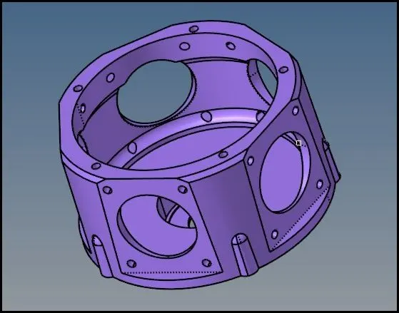
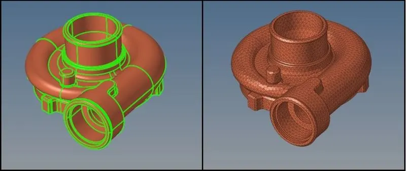
- Hear as shown in above image, only one models is there.
- For Direct 3D Tetra Mesh, there are two methods, we can use as below:
- Quick Tetra Mesh
- Volume Tetra Mesh
- We can use any of the method to create 3D Tetra Mesh.
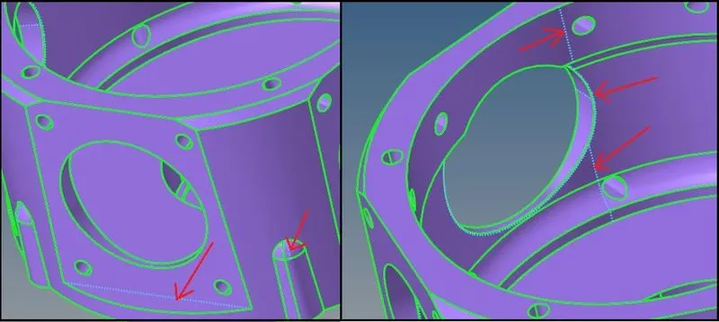
- First of all clear the model from any errors and remove extra edges and lines to avoid tet collapse as shown in below image:
Quick Tetra Mesh:
- Go to View Menu > Utility Menu
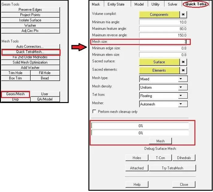
- Here select Geom. /Mesh.
- Select “Quick TetraMesh”.
- In selection of Quick TetraMesh, the Quick Tetra panel will open as in above image.
- Here just give the Target Mesh Size and required criteria for Mesh quality.
- On selecting “Mesh” button, it will check the model and perform the Geometry clean up as well as create the Tetra Mesh for the selected model.
Volume Tetra Mesh:
- For Volume Tetra Mesh, Go to 3D Panel > Tetra Mesh > Volume Tetra
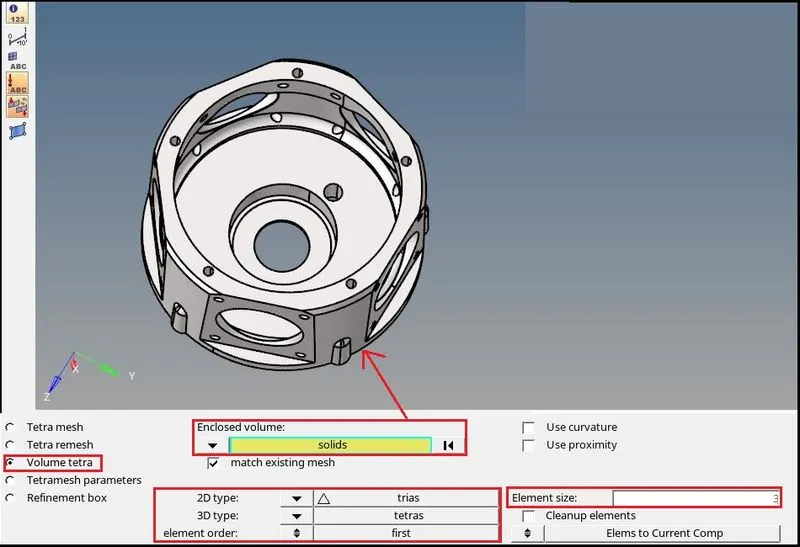
- Here Give required element size = 3 units.
- Select 2D type = Trias, 3D type = tetras and element order = first.
- After giving all parameters, select solid model for “Enclosed volume” and create Mesh.
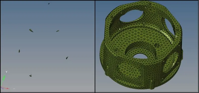
- After creating the 3D Tetra Mesh from one of the way mentioned above, we can correct the quality and make the Mesh model free from tet collapse as in above image.
_ _ _ _ _ _ _ _ _ _ _ _ _ _ _ _ _ _ _ _ _ _ _ _ _ _ _ _ _ _ _ _ _ _ _ _ _ _ _ _ _ _ _ _ _ _ _ _ _ _ _ _ _ _ _ _ _ _ _ _ _ _ _ _ _ _ _ _ _ _ _ _ _ _ _
(3) Tetra Mesh Generation Method: Quick Tetra Mesh / Volume Tetra Mesh
Criteria:
- Target Element Size: 4 Units
- Tet Collapse: 0.15
Models:
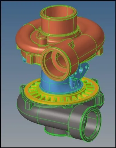
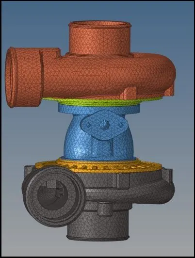
- As shown in above image, there are total 5 components in above model.
- Here in all components are meshed with “Volume Tetra Mesh” method one by one as below:
Component_1:
- Do necessary Cleanup and correct if there is any irregularities in the model.
- Remove extra or unnecessary edges in the model.
- As described in Method (2) – Tetra Mesh Generation by “Volume Tetra Mesh”, create direct 3D Tetra Mesh with 4 Units of Target element size.
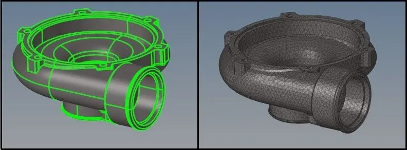
- Check for tet collapse. There should be no elements failing with tet collapse.
Component_2:
- Do necessary Cleanup and correct if there is any irregularities in the model.
- Create direct 3D Tetra Mesh with 4 Units of Target element size as above described procedure.
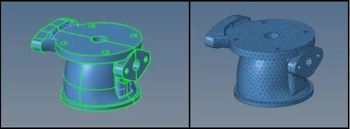
- Check for tet collapse. There should be no elements failing with tet collapse.
Component_3:
- Do necessary Cleanup and correct if there is any irregularities in the model.
- Create direct 3D Tetra Mesh with 4 Units of Target element size as above described procedure.
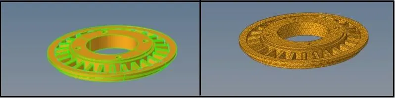
- Check for tet collapse. There should be no elements failing with tet collapse.
Component_4:
- Do necessary Cleanup and correct if there is any irregularities in the model.
- Create direct 3D Tetra Mesh with 4 Units of Target element size as above described procedure.
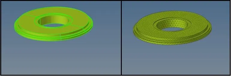
- Check for tet collapse. There should be no elements failing with tet collapse.
Component_5:
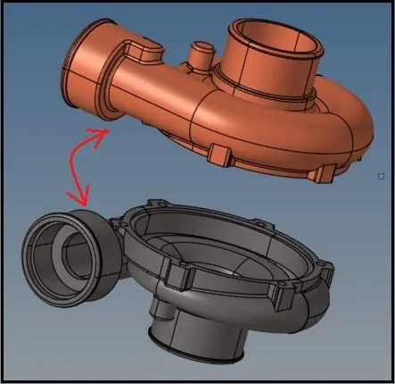
- Here we can see that Component_1 and Component_5 are identical to each other.
- So here we can copy the Mesh elements from Component_1 to Component_5.
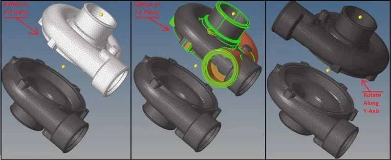
- As shown in above image, copy the Elements of Component_1 with creation of duplicate elements in X-Z plane with help of “Reflect” option and by using Y-Axis and Base node at the middle of the two components.
- After that, reflect the copied elements in Y-Z plane with creation of any duplicate or the same elements.
- Now rotate the Elements on alone Y-Axis up to 90 degree.
- After that make sure that the elements are moved in to proper collector or in to the Component_5.
- As we can see that by using “reflect” and “rotate”, Mesh is successfully copied for the Component_5.
After Creation of Tetra Mesh for all 5 components, Mesh model assembly can be shown as below:
_____________________________________________________________________________________________________________________
Inference:
- We can create 3D Tetra Mesh with different methods as per our convenience.
- As we can see from all methods, Generation of 3D Tetra Mesh from 2D Tria elements gives the best quality, as all checks can be done in 2D mesh for Minimum and Maximum length.
- Also after correction in 2D Mesh, when we create 3D Tetra Mesh from it, it will give less elements which are failing for Tet Collapse, which can be easily and quickly corrected, it consumes less time for good quality Tetra Mesh.
- In quick mesh generation or when there is less time for creation of Tetra Mesh, “Quick Tetra” is best option, because it gives Tetra Mesh quickly and it also checks for the geometry cleanup.
- Volume Tetra Mesh method is also important and very useful when we have only component and Mesh has to be created in shorter time conditions.
- After Generation of 3D Tetra Mesh, it is very important to check for Tet Collapse and correct the mesh in order to achieve 0 elements failing for Tet Collapse.
- Thus, with different methods, we can create 3D Tetra Mesh and by debugging for the elements failing for Tet Collapse, we can achieve Good Quality Tetra Mesh with any Tet Collapse.
_____________________________________________________________________________________________________________________
Thanks & Regards,
Dharmesh Joshi