Week 5 Bending of iPhone

Introduction:
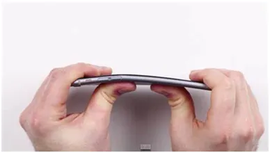
There are number of reports claiming that iPhone bends inside of people’s pocket. Some speculate that the tightness of your pants is significant here. The tighter they are, the more pressure they exert on your phone. It seems clear, too, that a lot depends on whether you lean forward when you sit or maintain a more correct upright position.
- You'd imagine that you'd be able to feel your bones or the chiseled tautness of your thigh muscles beginning to crush your phone. Perhaps, though, you're so engrossed in your work that you don't sense what you're doing to your status symbol until it's too late.
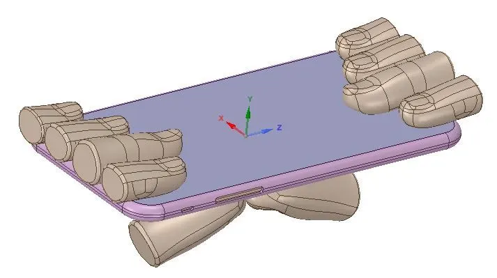
- So, to check the possibilities of the bending and how it bends on applying the load at different location from the back side, we have to do some analysis on it. We will do the analysis by pushing the back side of the iPhone with Pushing fingers while other fingers will hold it from top side.
________________________________________________________________________________________________________________________________________________________
Analysis
- Here we will do the analysis of iPhone bending in two different cases.
CASE_1: Pushing fingers located below the side buttons
CASE_2: Pushing fingers located below at the centre.
________________________________________________________________________________________________________________________________________________________
Geometry:
________________________________________________________________________________________________________________________________________
Material Properties:
Aluminium Alloy NL
Density: 2770 Kg/m3
Young’s Modulus: 71000 MPa
Poisson’s Ratio: 0.33
Yield Strength: 280 Mpa
Tangent Modulus: 500 Mpa
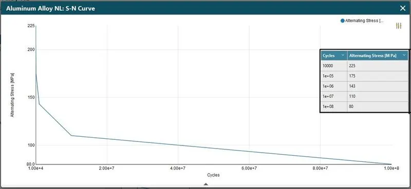
SN-Curve:
Glass
Density: 2520 Kg/m3
Young’s Modulus: 72000 MPa
Poisson’s Ratio: 0.2
Tensile Yield Strength: 250 Mpa
Compressive Yield Strength: 250 Mpa
Tensile Ultimate Strength: 460 Mpa
Polyethylene
Density: 950 Kg/m3
Young’s Modulus: 1100 MPa
Poisson’s Ratio: 0.42
Tensile Yield Strength: 25 Mpa
Tensile Ultimate Strength: 33 Mpa
________________________________________________________________________________________________________________________________________
Mesh:
Details:
- Global Element Size: Default
- Face Sizing : Contact faces at Pushing Fingers
Element Size = 4 mm
- of Nodes: 23039
- of Elements: 10790
Procedure:
- Import model in Static Structural in Geometry section.
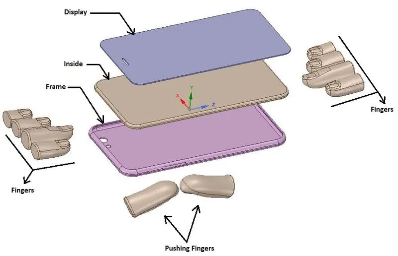
- There are total 13 components in Assembly.
- 8 Fingers, 2 Pushing fingers, Display, Inside and Frame.
To do the simulation without any error, we should reduce the number of surface in the model.
So merge the faces on the finger as much as we can.
After merging the faces on fingers, model should look like displayed below:
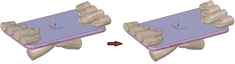
- We can see in above image that the model is much smooth and ready for analysis.
- In Mechanical model, rename all the components as Display, Frame, Inside, Pushing Fingers and Finger as suggested below:
- Assign the appropriate materials to components.
- Assign Glass material to Display.
- Assign Aluminium Alloy NL material to Frame.
- Assign Polyethylene material to Inside.
_ __ _ _ _ _ _ _ __ _ _ _ _ _ _ _ _ _ _ _ _ _ _ _ _ _ _ _ _ _ _ _ _ _ _ _ _ _ _ _ _ _ _ _ _ _ _ _ _ _ _ _ _ _ _ _ _ _ _ _ _ _ _ _ _ _ _ _ _ _ _ _ _
Geometric arrangements for CASE_1:
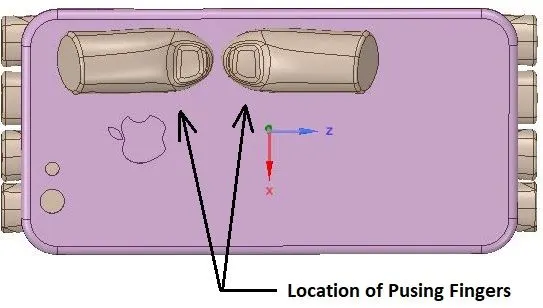
- Here the location of the Pushing Fingers will be at the bottom of the Side buttons of the iPhone as shown above.
Geometric arrangements for CASE_2:
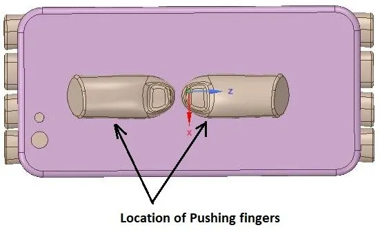
- Here the location of the Pushing Fingers will be at the centre of the Side buttons of the iPhone as shown above.
- To adjust the Pushing Fingers at the center, we have to move both the Pushing Fingers by 22.5 mm in X-direction and 10 mm in Z-direction.
- Also give behavior of the all fingers and the left Pushing finger as Rigid and keep Right Pushing finger behavior as Flexible.
_ __ _ _ _ _ _ _ __ _ _ _ _ _ _ _ _ _ _ _ _ _ _ _ _ _ _ _ _ _ _ _ _ _ _ _ _ _ _ _ _ _ _ _ _ _ _ _ _ _ _ _ _ _ _ _ _ _ _ _ _ _ _ _ _ _ _ _ _ _ _ _ _
Connections:
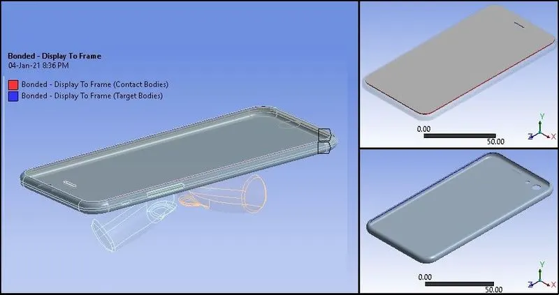
- First of all rename all automatically created contacts as definition.
- Also delete the contacts which have no significance.
Contact_1: Display To Frame
Type: Bonded
Contact_2: Display To Inside
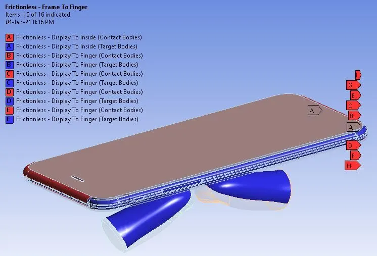
Display to all Fingers
Frame to all Pushing Fingers
Frame to all Fingers
Type: Frictionless
_ __ _ _ _ _ _ _ __ _ _ _ _ _ _ _ _ _ _ _ _ _ _ _ _ _ _ _ _ _ _ _ _ _ _ _ _ _ _ _ _ _ _ _ _ _ _ _ _ _ _ _ _ _ _ _ _ _ _ _ _ _ _ _ _ _ _ _ _ _ _ _ _
Joints:
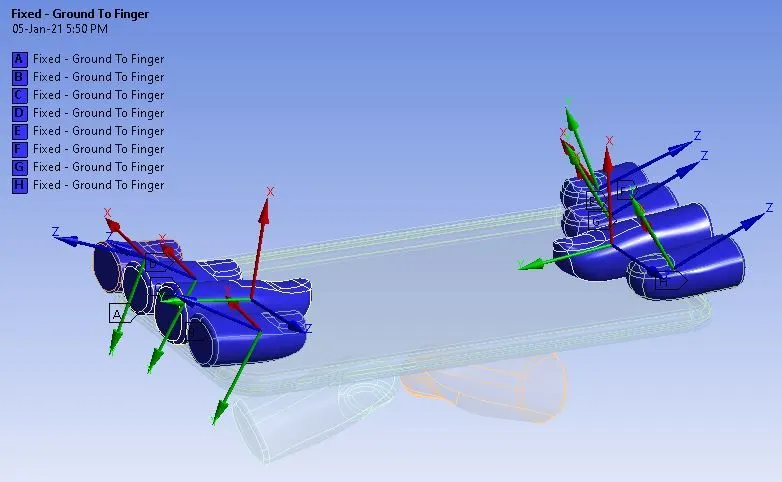
Joint_1
Connection Type: Body-Ground
Type: Fixed
Body: All Fingers
Joint_2
Connection Type: Body-Ground
Type: Translational
Body: All Pushing Fingers
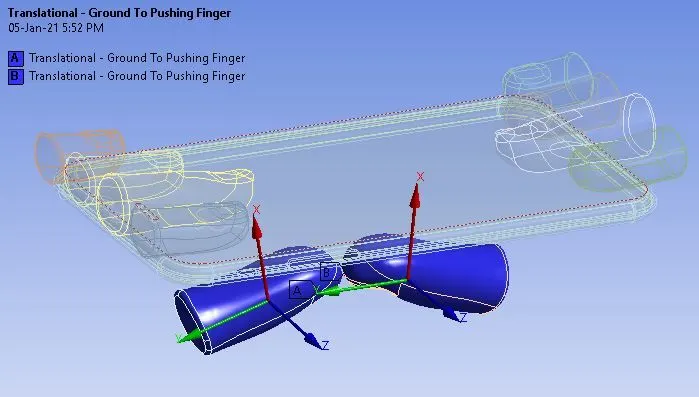
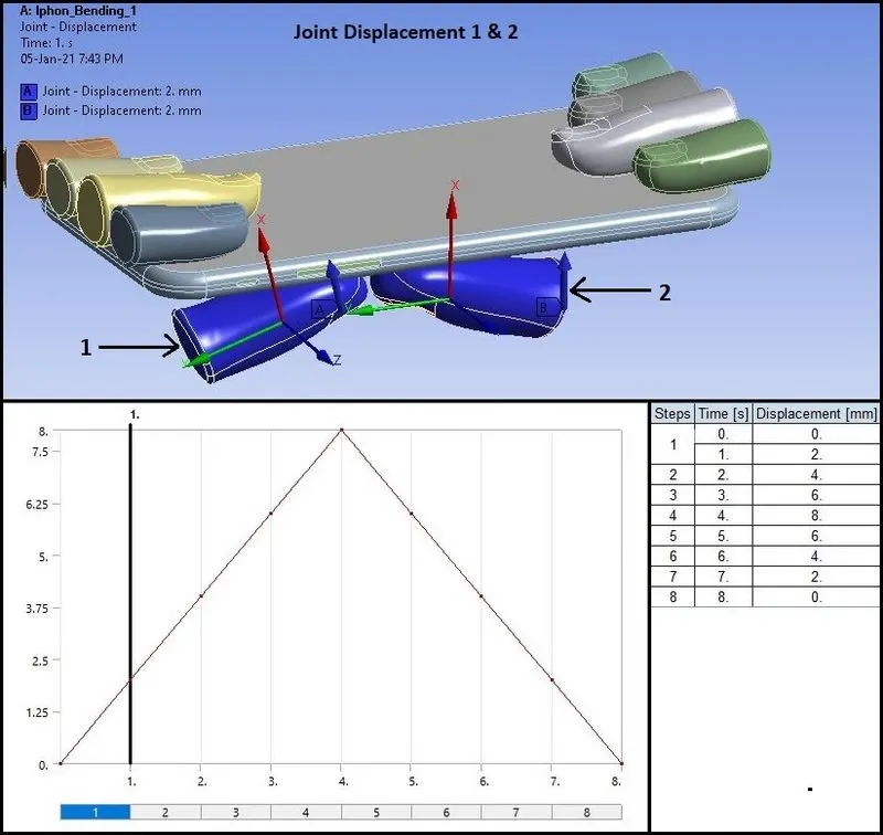
- Make sure that the X-Axis in translational joints are defined in Global Y-direction for both the joints.
_ __ _ _ _ _ _ _ __ _ _ _ _ _ _ _ _ _ _ _ _ _ _ _ _ _ _ _ _ _ _ _ _ _ _ _ _ _ _ _ _ _ _ _ _ _ _ _ _ _ _ _ _ _ _ _ _ _ _ _ _ _ _ _ _ _ _ _ _ _ _ _ _
Boundary Conditions:
- After meshing as described above, create Boundary Conditions as given below:
Analysis Settings:
- of Steps: 8
- Auto Time Stepping: Program Controlled
- Solver Type: Direct
- Weak Springs: Program Controlled
- Large Deflection: ON
- Nonlinear Controls:
- Stabilization: Constant
- Method: Energy
- Energy Dissipation Ratio: 0.1
- Output Controls: Yes to All
Other Boundary conditions for joints are as given below:
Fixed Support:
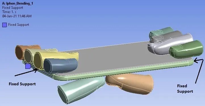
- To fix or support the assembly, two faces of “Inside” body has been fixed from movement.
- Now we want to allow the iPhone to move along the Y-axis and restrict the movement in X & Z direction.
Displacement:
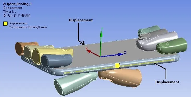
- Here we have allowed the displacement of iPhone I Y-Direction and for X & Z direction, displacement is constant or 0.
Joint Displacement_1 & 2:
Joint: Translational (Ground to Pushing Finger)
Type: Displacement
DOF: X-Displacement
_ __ _ _ _ _ _ _ __ _ _ _ _ _ _ _ _ _ _ _ _ _ _ _ _ _ _ _ _ _ _ _ _ _ _ _ _ _ _ _ _ _ _ _ _ _ _ _ _ _ _ _ _ _ _ _ _ _ _ _ _ _ _ _ _ _ _ _ _ _ _ _ _
Solution:
- After giving proper boundary conditions, create desired solutions for output results.
- Create Solutions for :
- Equivalent Stress For Whole Setup & for Frame
- Equivalent Strain for the Whole Setup & for Frame
- Directional Deformation (Y-Direction) for Whole Setup & for Frame
- Safety Factor for Frame
- Fatigue Life of the Frame
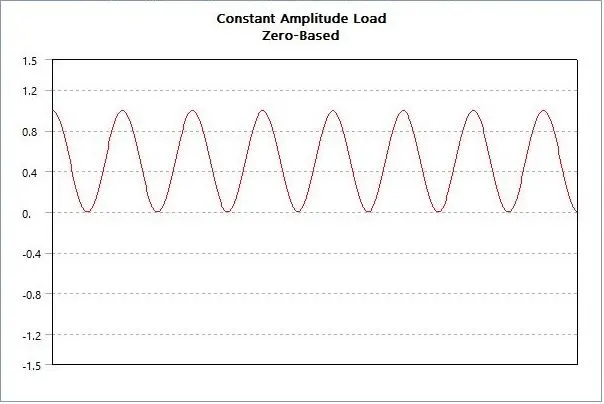
- Fatigue Life will be generated by Constant Amplitude Load at Zero Based Cycles as given below:
________________________________________________________________________________________________________________________________________________________
Results:
- Now we will see the results for requested solutions.
CASE_1:
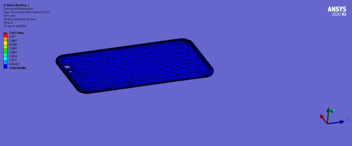
Directional Deformation (Y-Direction):
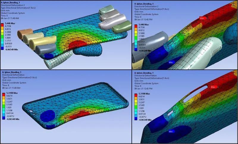
- Here the maximum deformation of the iPhone assembly is 5.446 mm.
- Maximum deformation of the Frame is 5.3198 mm can be seen from above image.
- So we can say that maximum deformation among all parts occurs on the Frame.
Deformation Plot & Data (Frame):
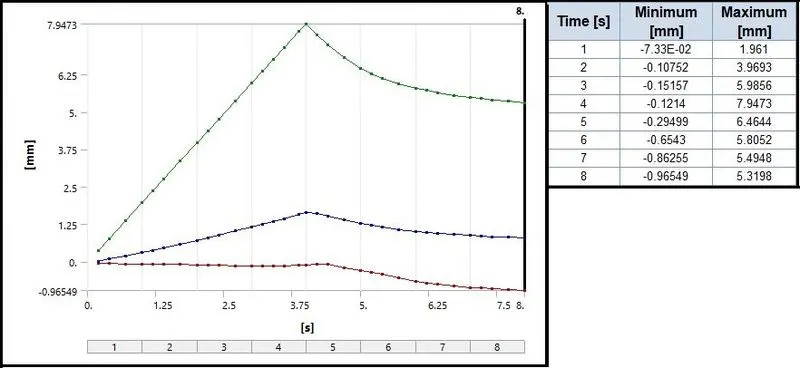
- Also we can see the negative value of deformation, which indicated that on the removal of load or when the motion of Pushing fingers are in reverse or downward, iphone/ Frame is trying to get the original shape.
- So to gain the original shape, negative displacement happens.
- Also we can see from the plot and the Data, that from step 1 to 4, deformation is increasing from 0 to 7.94 mm maximum.
- But on the removal of load, due to some elasticity, decrease in deformation values up to 5.32 mm can be observed.
- Also we can see from the data that from the first step, there are negative and positive deformations are happening.
- It is due to tension on the upper surface and compression on the lower surface of the Phone.
Stress:
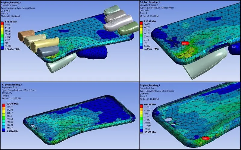
- Here overall Maximum stress is 832.51 Mpa.
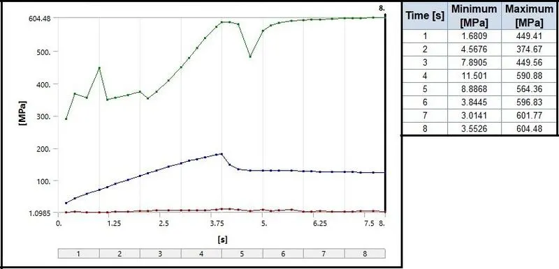
- Frame has the maximum stress of 604.48 Mpa.
- Stress on the Frame is above the Yield value 280Mpa, so we can say there will be some plastic deformation in the Frame.
Stress Plot and Data (Frame):
Strain:
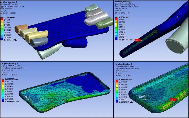
- Maximum strain for the assembly is 0.16584 mm.
- Maximum strain for the Frame is 0.0087315 mm.
Strain Plot and Data (Frame):
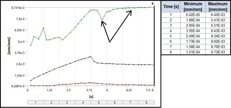
- We can observe that after 4 steps, there is a little decrease in strain from 8.43 E-03 to 8.24 E-03 mm. But after 5th step it increases and remains nearly stable.
- So on removal of load there is a residual strain in the Frame and the shape cannot be regained more.
Safety Factor (Frame):
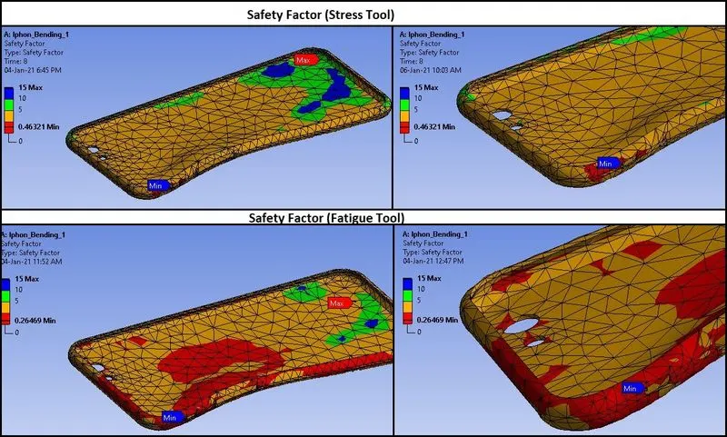
- There are two types of Safety Factors. One is given by Stress Tool and another given by Fatigue Tool.
- Stress tool Safety factor is calculating if a single load will exceed the limit defined parameter in the case.
- Here we have given Tensile Yield Strength to calculate the Safety factor.
- Tensile Yield strength of frame material (Aluminium Alloy NL) is 280 Mpa.
- So Safety Factor = Tensile Yield Strength (Frame)/ Max. Equivalent Stress (Frame) = 280/604.48= 0.4632. This is true from the above results.
- Fatigue Tool Safety Factor is based on the load cycles.
- Here we have given Analysis type as Stress life and S-N curve is also given.
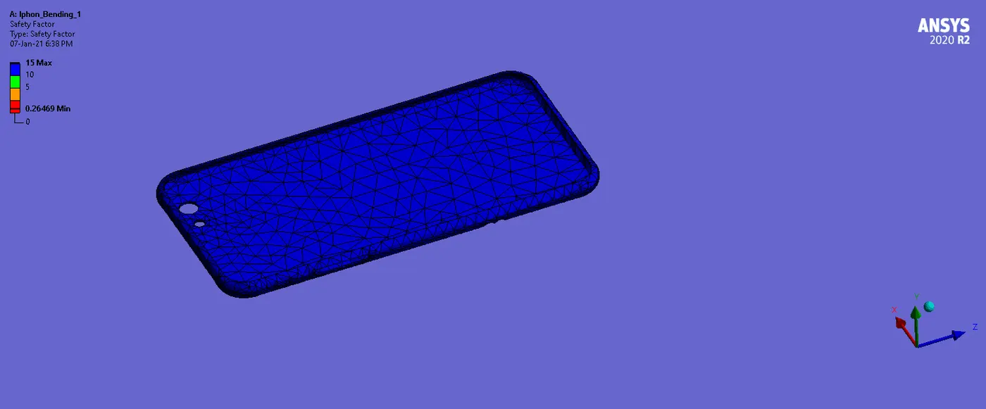
- So based on the load cycles, overall Safety Factor is 0.26469.
- In both the Safety factors, we can observe the less safety for the Assembly or Frame is near the Side button of the Frame. From that area crack propagation and failure can start.
Life (Frame):
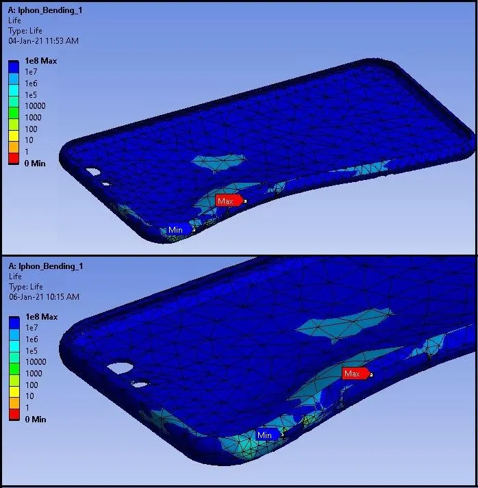
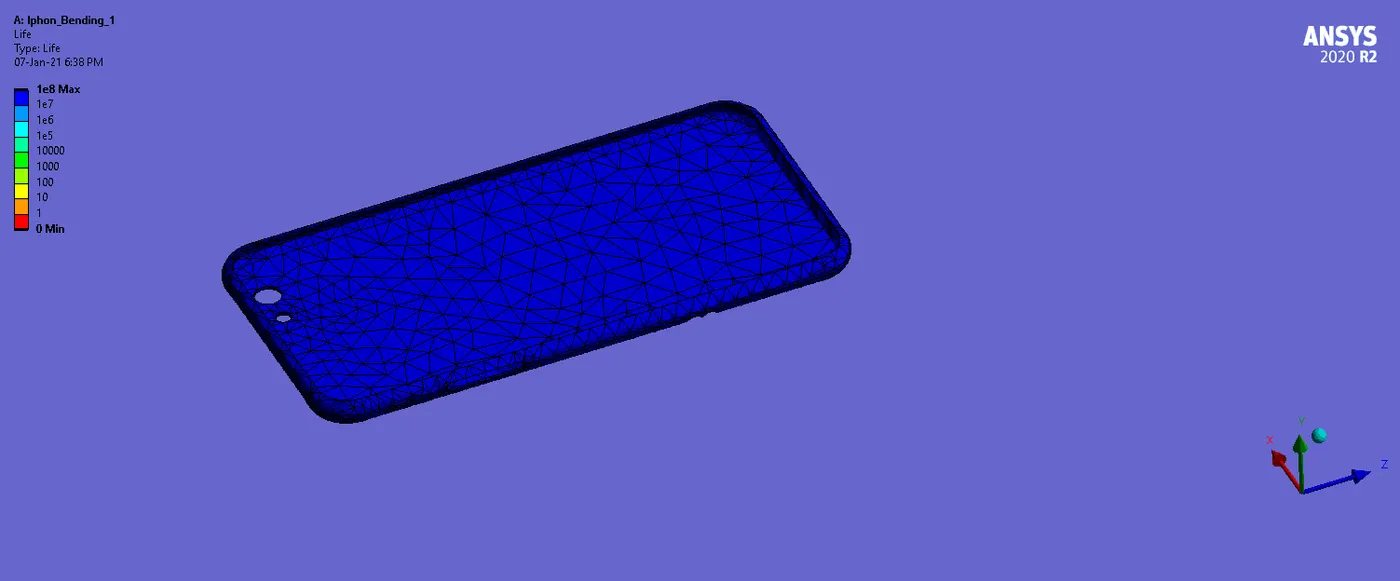
- From above results of Fatigue life, we can say that maximum life of the component is 1e+8.
- But the minimum is 0 here.
- So we can say that, at the given load, the area shown for minimum life in the above image have no more life and it is failing due to plastic deformation or it can break.
_ __ _ _ _ _ _ _ _ _ _ _ _ _ _ _ _ _ _ _ _ _ _ _ _ _ _ _ _ _ _ _ _ _ _ _ _ _ _ _ __ _ _ _ _ _ _ _ _ _ _ _ _ _ _ _ _ _ _ _ _ _ _ _ _ _ _ _ _ _ _ _ _ _ _ _ _ _ _ _ _ _ _ _ _ _ _ _ _ _ _ _ _ _ _ _
CASE_2:
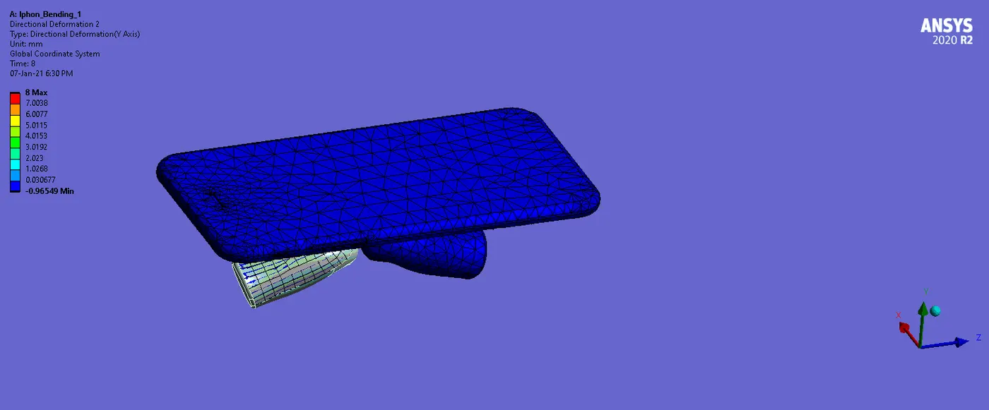
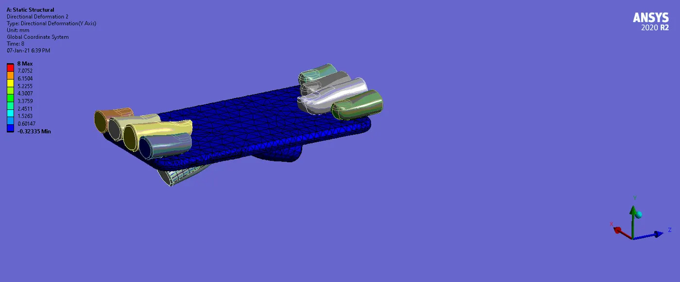
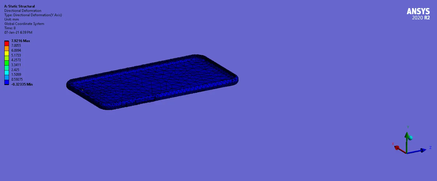
Directional Deformation (Y-Direction):
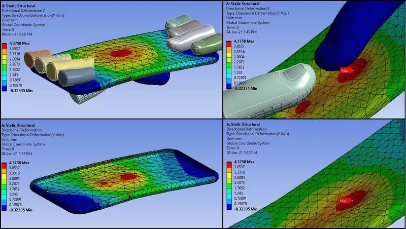
- Here the maximum deformation of the iPhone assembly is 4.3758 mm.
- Maximum deformation of the Frame is also 4.3758 mm can be seen from above image.
- So we can say that Frame is attending maximum deformation when assembly is attending maximum deformation and both are same.
Deformation Plot & Data (Frame):
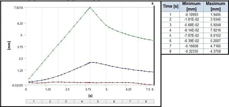
- Also we can see the negative value of deformation as in CASE_1, which indicated that on the removal of load or when the motion of Pushing fingers are in reverse or downward, iphone/ Frame is trying to get the original shape.
- We can see from the plot and the Data, that from step 1 to 4, deformation is increasing from 0 to 7.92 mm maximum.
- But on the removal of load, due to some elasticity, decrease in deformation values up to 5.2 mm can be observed.
- Here also we can observe tension and compression due to deformation on both the sides of the Phone.
Stress:
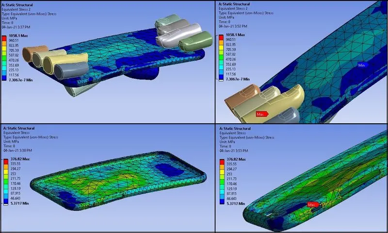
- Here overall Maximum stress is 1058.1 Mpa.
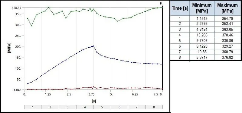
- Frame has the maximum stress of 376.82 Mpa.
- Stress on the Frame is above the Yield value 280Mpa, so we can say there will be some plastic deformation in the Frame.
Stress Plot and Data (Frame):
Strain:
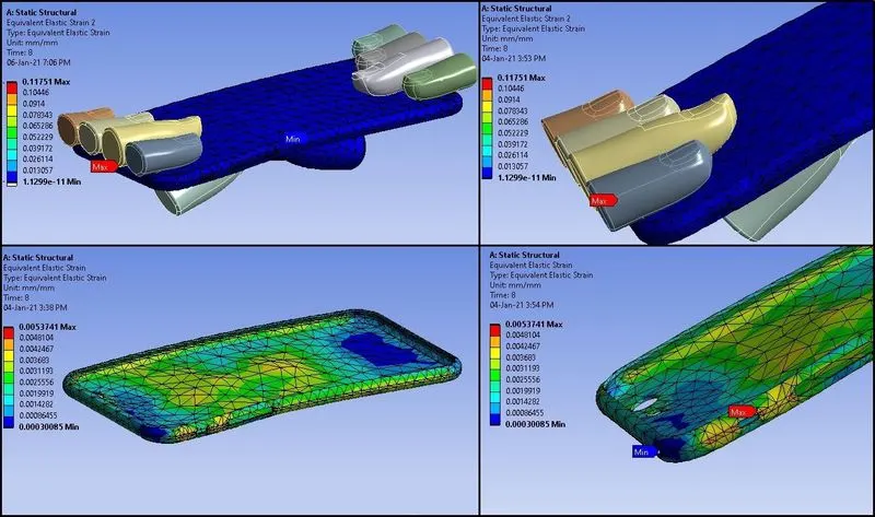
- Maximum strain for the assembly is 0.11751 mm.
- Maximum strain for the Frame is 0.0053741 mm.
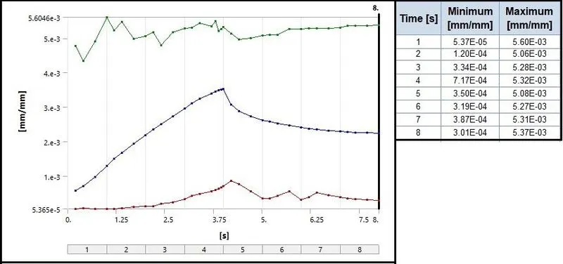
- We can observe that after 4 steps, there is a little decrease in strain from 5.32 E-03 to 5.08 E-03 mm. But after 5th step it increases and remains nearly stable.
- So on removal of load there is a residual strain in the Frame and the shape cannot be regained more.
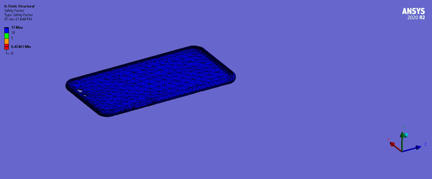
Safety Factor (Frame):
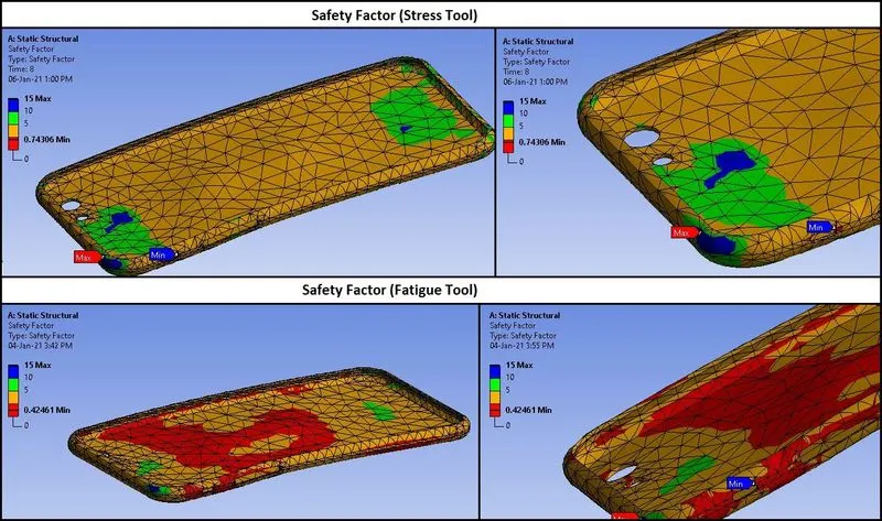
- So Stress Tool Safety Factor = Tensile Yield Strength (Frame)/ Max. Equivalent Stress (Frame) = 280/376.82= 0.7430. This is true from the above results.
- Based on load Cycles, Fatigue Tool Safety Factor is 0.42461.
- In both the Safety factors, we can observe the less or minimum safety for the Assembly or Frame is near the Side button of the Frame. From that area crack propagation and failure can start.
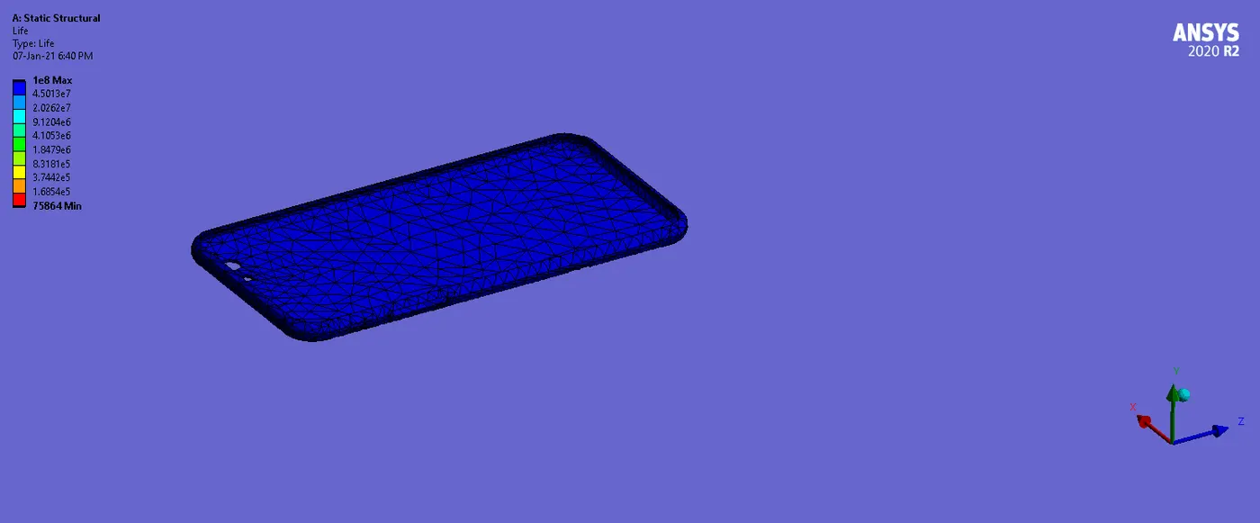
Life (Frame):
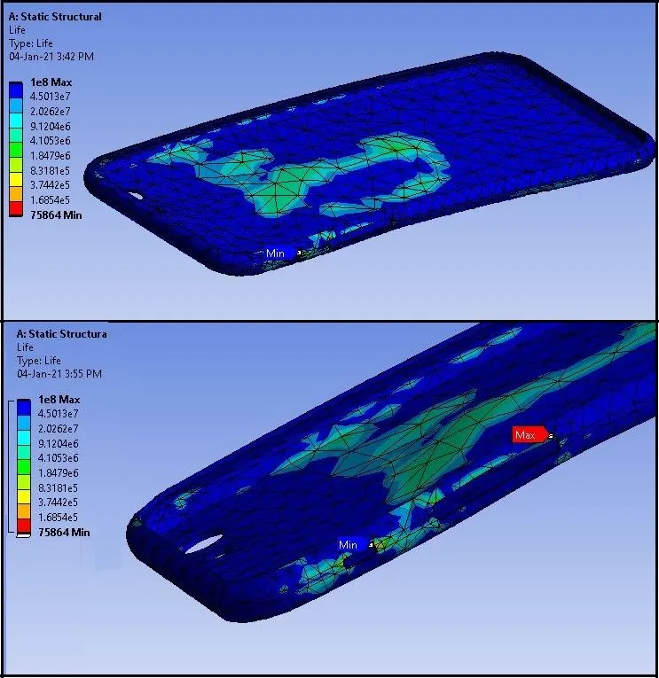
- From above results of Fatigue life, we can say that maximum life of the component is 1e+8.
- Here the minimum amount of life cycles for given loading is 75864.
- So we can say that, at the given cyclic loading, the Phone will survive up to 75864 cycles. Or that least the area near the side buttons or minimum life will survive up to minimum 75864 cycles. After that it can break.
________________________________________________________________________________________________________________________________________________________
Comparison:
- Here we will see the comparison for the CASE_1 & CASE_2 for the “Frame”.

- From above table of comparison, we can say that in CASE_2 where the load is applied at the centre, produces nearly half of the stress compared to CASE_1.
- Also strain in the CASE_2 is little low, which shows less plastic strain compared to CASE_1.
- Deformation is less in CASE_2, compared to CASE_1, which is due to uniform distribution of load.
- In CASE_2, load applied is at the centre, so it will be distributed in all directions and the resultant force will be less. Where in CASE_1, load applied is at the side or below the side buttons, so it can deform more in one direction.
- Also both safety factors value is higher in CASE_2, It means in CASE_2, Phone will hold more for single load or for cyclic loading conditions, which is good and can resist more to load.
- But overall in both the cases, safety factor is less than 1, which means it will fail or likely to fail.
- Life in CASE_2, is more than un CASE_1, So as per CASE_1, iPhone will break earlier than CASE_2.
________________________________________________________________________________________________________________________________________________________
Conclusion:
- From above results, we can conclude that on the repetitions of load on the iPhone at the centre can withstand more or have more life.
- If the repetitive load is at sides, it may bend more and it can break at early stages of loading.
- For the centre loading conditions, iPhone is more durable than side loading conditions.
- In both the cases, stress is going beyond the yield limit, which can cause plastic deformations or failure.
- So to Make the iPhone more durable and to increase the strength, more upscale material should be used.
- Percentage amount of Zinc addition to Aluminium Alloy can be better composition and can exhibit more impact strength.
- Also we can keep iPhone in the shirt pocket instead of pant pockets and in a protective case.
________________________________________________________________________________________________________________________________________________________
References:
- The crisis of the bending iPhone 6: Solving the problem - CNET
- (6) iPhone 6 Plus Bend Test - YouTube
- Apple knew iPhone 6 was prone to bending that caused “touch disease” (idownloadblog.com)
- Safety factor and fatigue life - effective design measures - CAEbay
- Can You Fix a Bent iPhone? (Answered by a Local Expert) (siyanda.org)
________________________________________________________________________________________________________________________________________________________
Animations:
CASE_1:
Directional Deformation (Y-Direction):
Whole_Setup
Frame
Fatigue_Safety Factor:
Life:
_ __ _ _ _ _ _ _ _ _ _ _ _ _ _ _ _ _ _ _ _ _ _ _ _ _ _ _ _ _ _ _ _ _ _ _ _ _ _ _ __ _ _ _ _ _ _ _ _ _ _ _ _ _ _ _ _ _ _ _ _ _ _ _ _ _ _ _ _ _ _ _ _ _ _ _ _ _ _ _ _ _ _ _ _ _ _ _ _ _ _ _ _ _ _ _
CASE_2:
Directional Deformation (Y-Direction):
Whole_Setup
Frame
Fatigue_Safety Factor:
Life:
________________________________________________________________________________________________________________________________________
Thanks & Regards,
Dharmesh Joshi