Week 5 Sphere pressing on a plate

Introduction to Plastic Deformation
The relationship between stress and strain is generally linear and reversible up until the yield point and the deformation is elastic. The linear relationship for a material is known as Young's modulus. Above the yield point, some degree of permanent distortion remains after unloading and is termed plastic deformation.
This type of deformation is not undone simply by removing the applied force. An object in the plastic deformation range, however, will first have undergone elastic deformation, which is undone simply be removing the applied force, so the object will return part way to its original shape. Soft thermoplastics have a rather large plastic deformation range as do ductile metals such as copper, silver, and gold. Steel does, too, but not cast iron. Hard thermosetting plastics, rubber, crystals, and ceramics have minimal plastic deformation ranges. An example of a material with a large plastic deformation range is wet chewing gum, which can be stretched to dozens of times its original length.
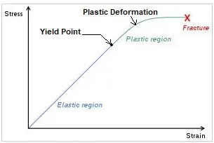
Under tensile stress, plastic deformation is characterized by a strain hardening region and a necking region and finally, fracture (also called rupture). During strain hardening the material becomes stronger through the movement of atomic dislocations. The necking phase is indicated by a reduction in cross-sectional area of the specimen. Necking begins after the ultimate strength is reached. During necking, the material can no longer withstand the maximum stress and the strain in the specimen rapidly increases. Plastic deformation ends with the fracture of the material.
______________________________________________________________________________________________________________________________________
Analysis:
Here we will see the Analysis for Plastic deformation of a Nonlinear Plate due to impact of Sphere body.
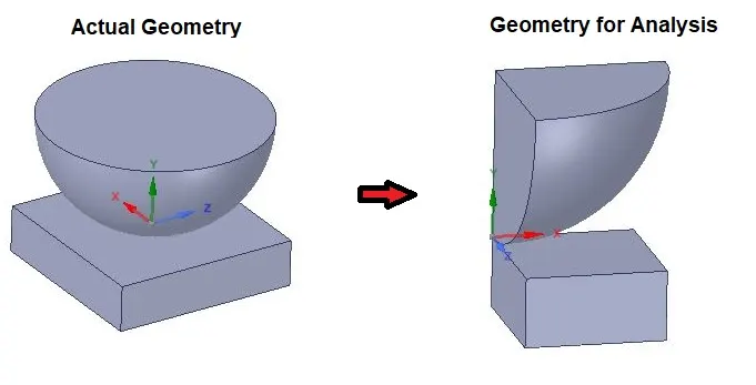
We will take a portion of the Plate and a Sphere which can be taken as Symmetric geometry for saving time and calculation of whole body.
______________________________________________________________________________________________________________________________________
Geometry:
______________________________________________________________________________________________________________________________________
Material:
- Material Specifications for Plate:
Structural Steel NL
Density: 7850 Kg/m3
Young’s Modulus: 2E+05 MPa
Poisson’s Ratio: 0.3
Yield Strength: 250 MPa
Tangent Modulus: 1450 Mpa
- Material Specifications for Plate:
Structural Steel
Density: 7850 Kg/m3
Young’s Modulus: 2E+05 MPa
Poisson’s Ratio: 0.3
Tensile Yield Strength: 250 Mpa
Compressive Yield Strength: 250 MPa
Tensile Ultimate Strength: 460 Mpa
________________________________________________________________________________________________________________________
Mesh:
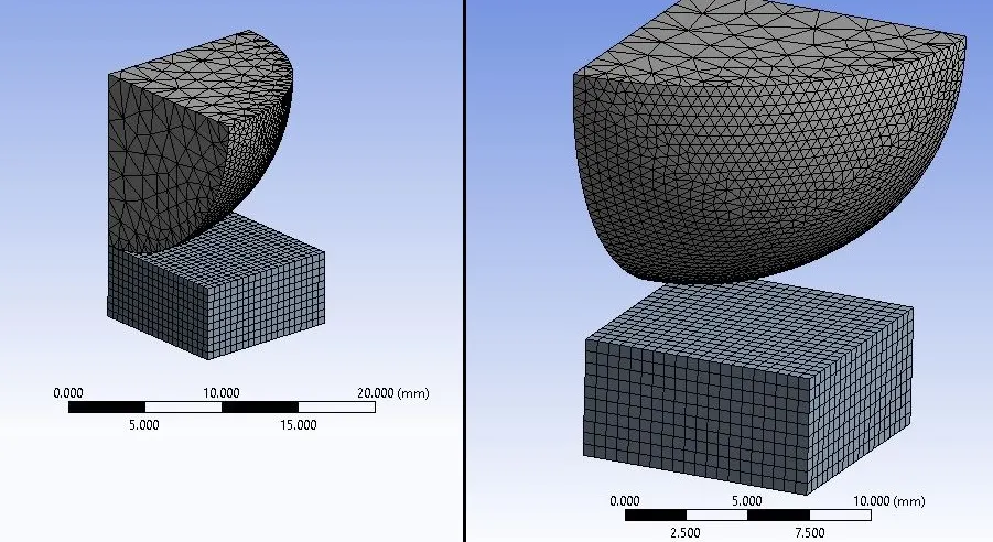
Details:
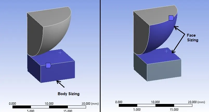
- Global Element Size: Default
- Body Sizing : Plate
Element Size = 0.5 mm
- Face Sizing : Contact Faces of Sphere & Plate (2 Faces)
Element Size = 0.5 mm
- No. of Nodes: 2932
- No. of Elements: 10039
________________________________________________________________________________________________________________________
Procedure:
- Import model in Static Structural named as “Skill_Lync_Sphere_pressing on plate.STEP” in Geometry section.
- Then go to Mechanical model section.
- Check or Rename the Parts of the setup as “Sphere”, and “Plate” as shown in above geometry image.
- Sphere material is by default as Structural Steel.
- Assign “Structural Steel NL” material to Plate.
Symmetry:
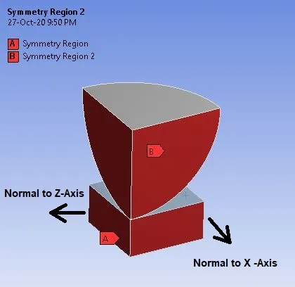
- As shown in above image, Create Symmetry Region for one side of the faces and give Symmetry Normal to Z—Axis.
- Also create Symmetry Region for another Side faces and give it Symmetry Normal to X-Axis.
This way, we have created a complete Plate and the Sphere portion with help of Symmetry.
Connections:
- Delete automatically created contact and create new contact as given below:
Contact:
Contact Body = Sphere
Target Body = Plate
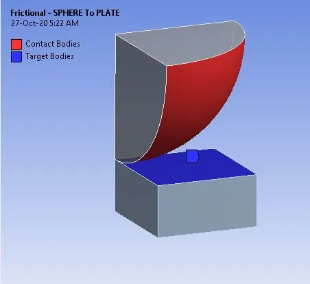
- As shown in above image, one face of the Sphere is set to Contact face and one face of the Plate is set to Target Face.
Settings for the Contact:
- Type: Frictional
- Friction Coefficient: 0.74
Boundary Conditions:
- After meshing as described above, create Boundary Conditions as given below:
Analysis Settings:
- No.of Steps: 4
- Solver Type: Direct
- Large Deflection: ON
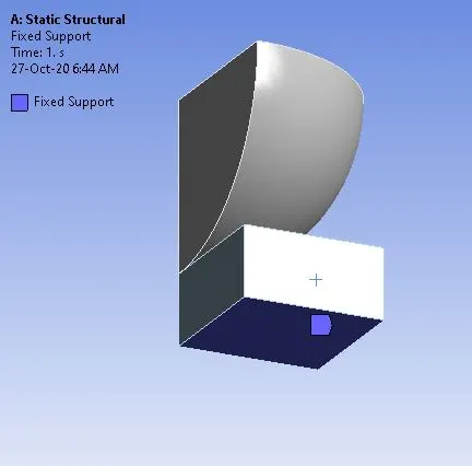
Fixed Support:
- Apply Fixed Support for fixing the movement of Plate its location as given below:
Displacement:
Direction: -Y (Negative)
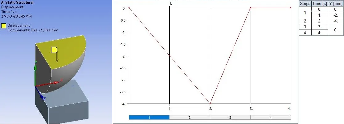
- Give Displacement to Sphere from 0 to 4 and retract it again to 0 in 4 steps as shown in above image.
Solution:
- After giving proper boundary conditions, create desired solutions for output results.
- Create Solutions for :
- Directional Deformation in Y-axis for Whole Setup
- Total Deformation
- Equivalent Stress For Plate
- Equivalent Strain For Plate
- Equivalent Plastic Strain for Plate
- Equivalent Strain for Sphere
________________________________________________________________________________________________________________________
Results:
- Now we will see all results.
Stress Contours for Plate:
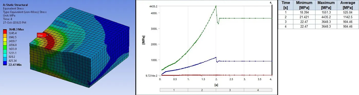
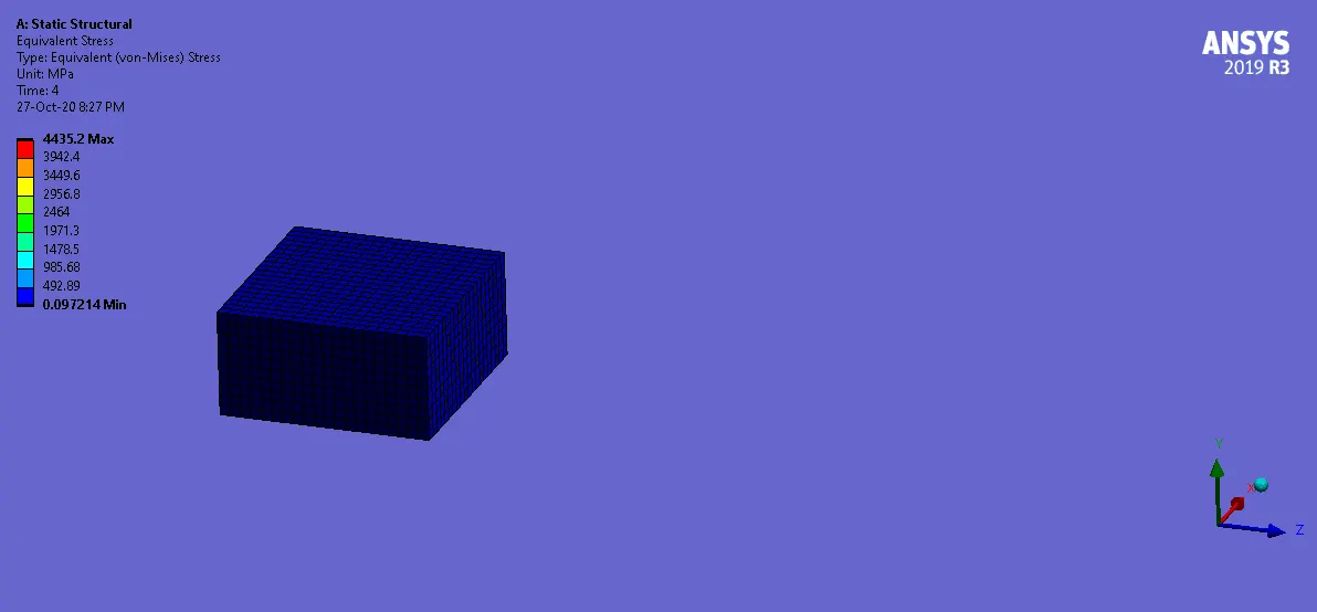
- We can see from above image that in the first step of ramping, stress exceeds the yield point.
Strain Contours for Plate:
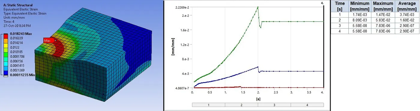
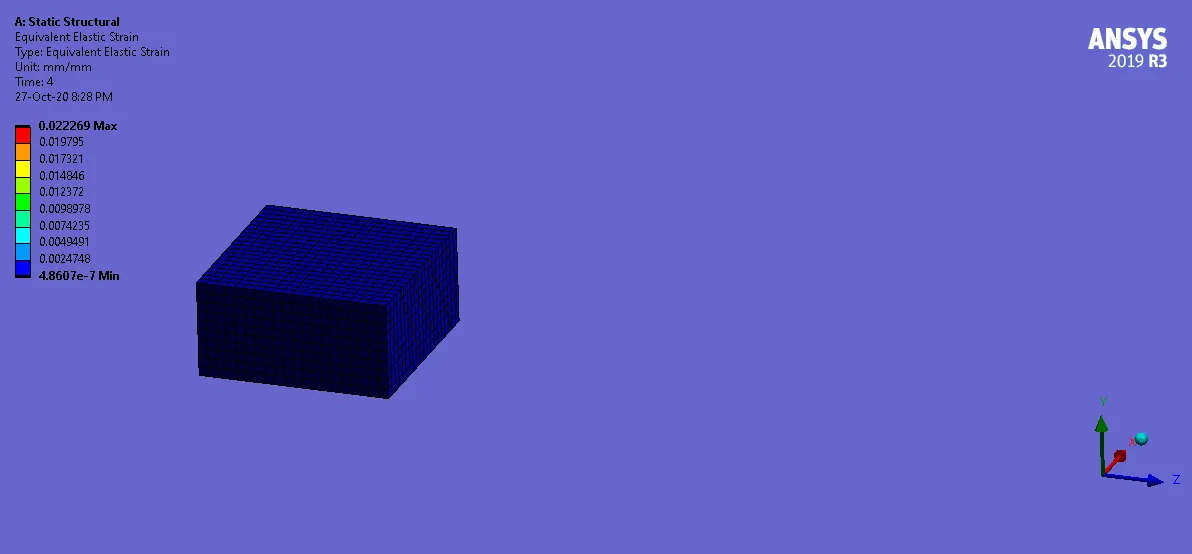
- We can observe very low stain in elastic region from above image.
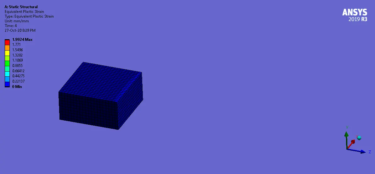
Plastic Strain for Plate:
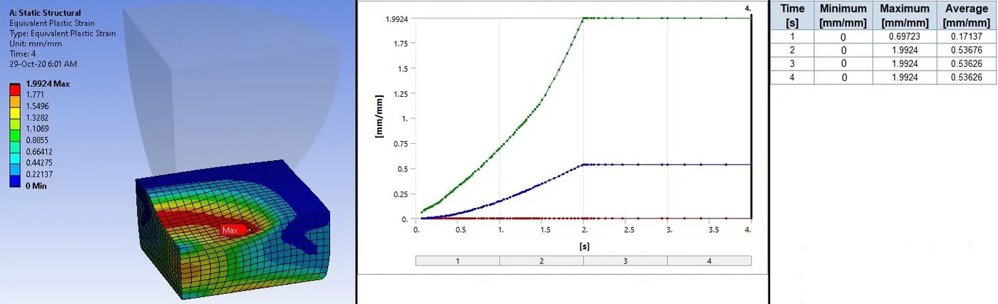
- On ramping of sphere on plate, Plastic or residual strain reaches up to 2 mm and becomes stable.
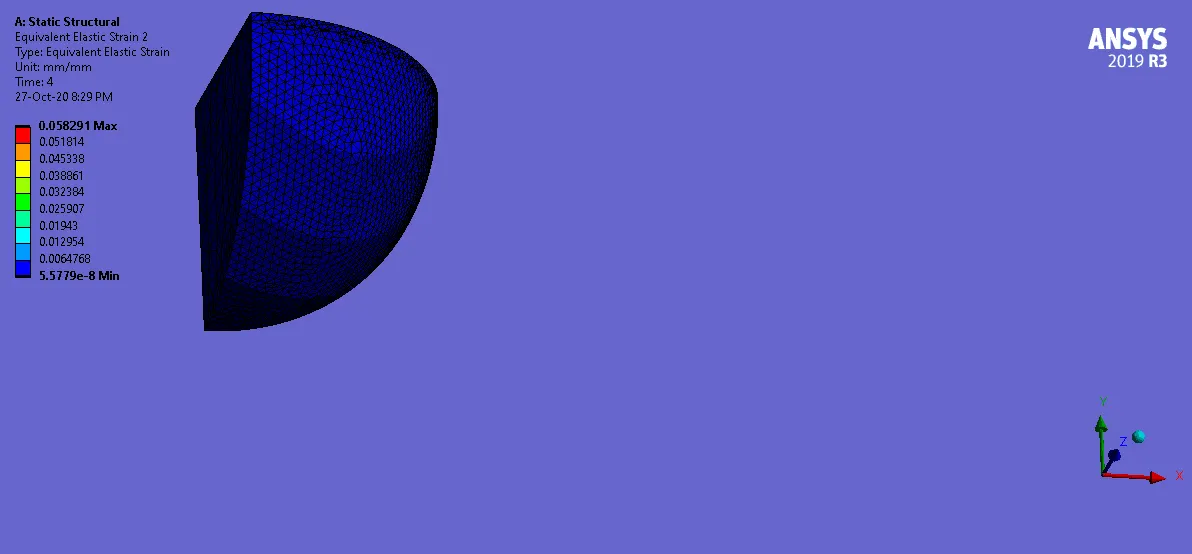
Strain Contours for Sphere:
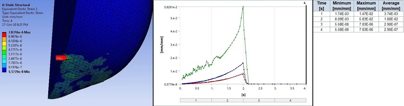
- Here in above image, we can see that material of sphere is structural steel. So maximum value of strain which is elastic in nature and very low compared to Plate.
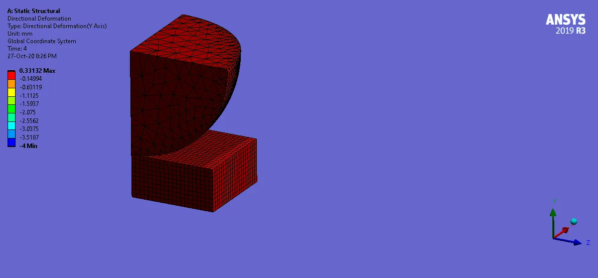
Deformation in Y-Direction:
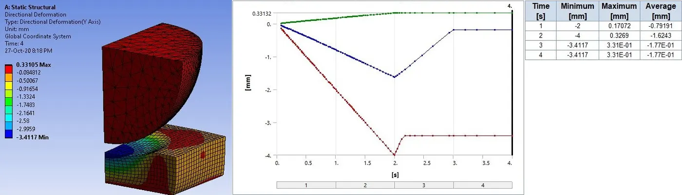
- From above image we can see the displacement of sphere occurs up to step 2 and then it retracts.
- We can see from the plot that at the step 2 , displacement of sphere becomes 4 mm which is maximum in this case.
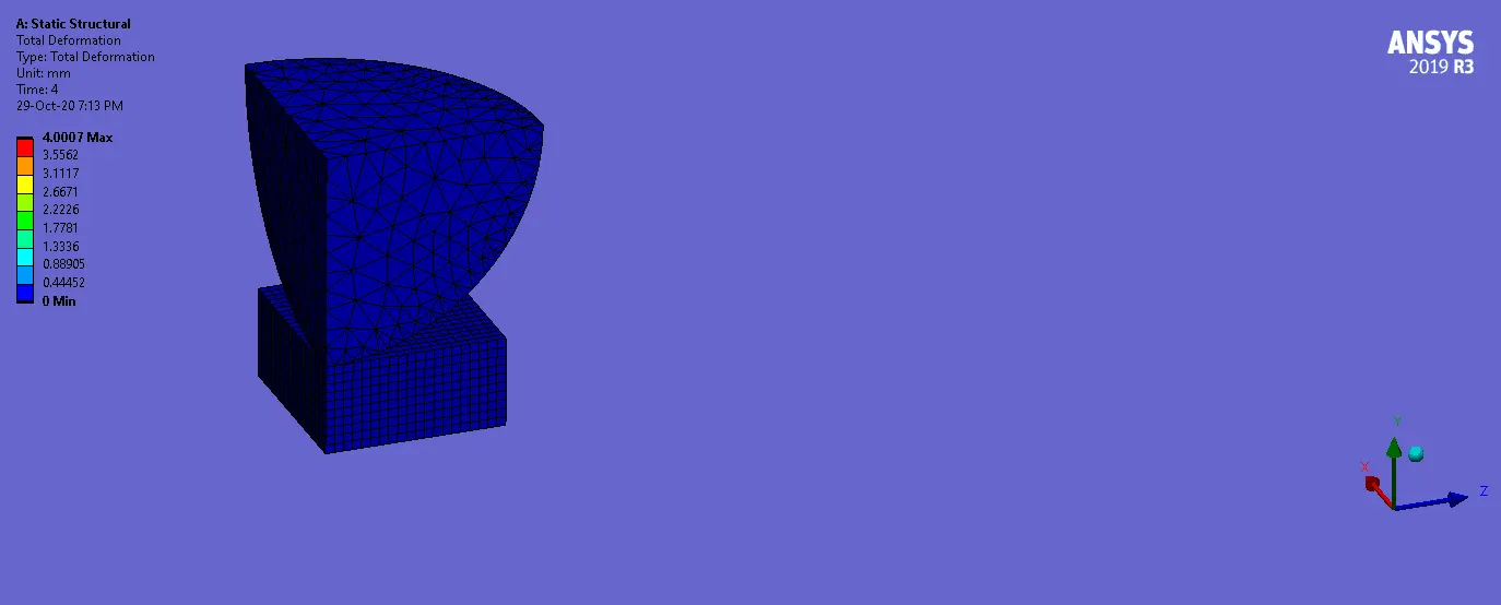
Total Deformation:
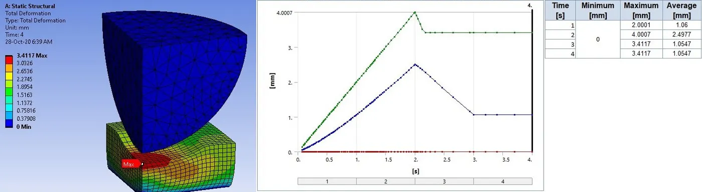
- Above image is evidence of the Plastic deformation.
- We can see the deformation on the plate at the location of hitting of sphere.
- Also from the plot, we can see that from step 3, deformation becomes stable. It means there is a permanent deformation on plate.
________________________________________________________________________________________________________________________
Conclusion
- From all images and plots, we can observe displacement of Sphere in Y direction and it hits a Plate and retracts.
- In elastic deformation, when load is removed, material regains its shape. But in our case, it is not regaining its shape. It means there is Plastic Deformation.
- When given load crosses the elastic limit, plastic deformation occurs. It also can be described by the contours and plots of Plastic strain.
- So we can say that the Plastic Deformation of a Nonlinear Flat Plate has been captured.
_______________________________________________________________________________________________________________________
Animations:
Stress on Plate:
Strain on Plate:
Strain on Sphere:
Plastic Strain in Plate:
Deformation in Y-Direction:
Total Deformation:
______________________________________________________________________________________________________________________________________
Thanks & Regards,
Dharmesh Joshi