Week 3 Sheet metal Bending challenge

Introduction to Sheet Metal Bending
Bending of sheet metal is a common and vital process in manufacturing industry. Sheet metal bending is the plastic deformation of the work over an axis, creating a change in the part's geometry. Similar to other metal forming processes, bending changes the shape of the work piece, while the volume of material will remain the same. In some cases bending may produce a small change in sheet thickness. For most operations, however, bending will produce essentially no change in the thickness of the sheet metal. In addition to creating a desired geometric form, bending is also used to impart strength and stiffness to sheet metal, to change a part's moment of inertia, for cosmetic appearance and to eliminate sharp edges.
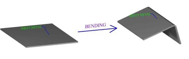
- Metal bending enacts both tension and compression within the material. Mechanical principles of metals, particularly with regard to elastic and plastic deformation, are important to understanding sheet metal bending and are discussed in the fundamentals of metal forming section. The effect that material properties will have in response to the conditions of manufacture will be a factor in sheet metal process design. Usually sheet metal bending is performed cold but sometimes the work may be heated, to either warm or hot working temperature.
- Most sheet metal bending operations involve a punch die type setup, although not always. There are many different punch die geometries, setups and fixtures. Tooling can be specific to a bending process and a desired angle of bend. Bending die materials are typically gray iron, or carbon steel, but depending on the work piece, the range of punch-die materials varies from hardwood to carbides. Force for the punch and die action will usually be provided by a press. A work piece may undergo several metal bending processes. Sometimes it will take a series of different punch and die operations to create a single bend. Or many progressive bending operations to form certain geometry.
- Sheet metal is referenced with regard to the work piece when bending processes are discussed in this section. However, many of the processes covered can also be applied to plate metal as well. References to sheet metal work pieces may often include plate. Some bending operations are specifically designed for the bending of differently shaped metal pieces, such as for cabinet handles. Tube and rod bending is also widely performed in modern manufacturing.
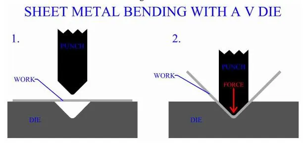
- Bending processes differ in the methods they use to plastically deform the sheet or plate. Work piece material, size and thickness are important factors when deciding on a type of metal bending process. Also important is the size of the bend, bend radius, angle of bend, curvature of bend and location of bend in the work piece. Sheet metal process design should select the most effective type of bending process based on the nature of the desired bend and the work material. Many bends can be effectively formed by a variety of different processes and available machinery will often determine the bending method.
- One of the most common types of sheet metal manufacturing processes is V bending. The V shaped punch forces the work into the V shaped die and hence bends it. This type of process can bend both very acute and very obtuse angles, also anything in between, including 90 degrees.
________________________________________________________________________________________________________________________
Analysis:
Structural analysis of sheet metal bending process will be categorized in 5 different cases with some changes of Material or Parameters are as given below:
Case_1: Aluminium Alloy 1199
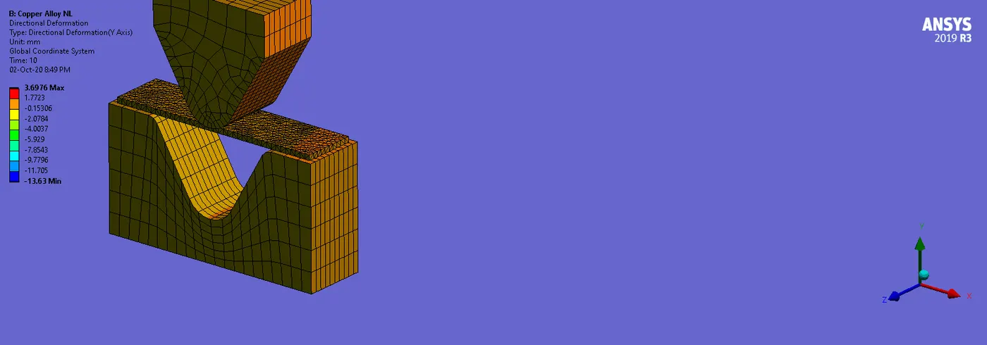
Case_2: Copper Alloy NL
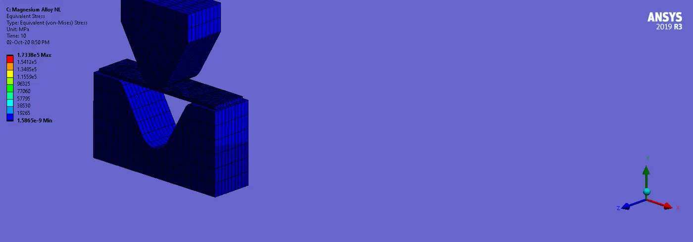
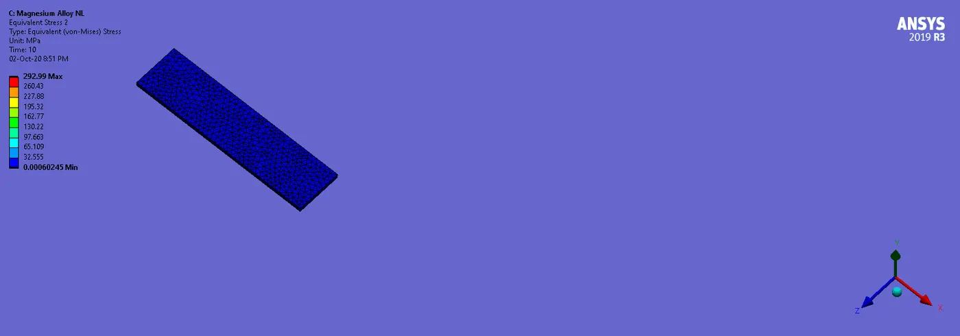
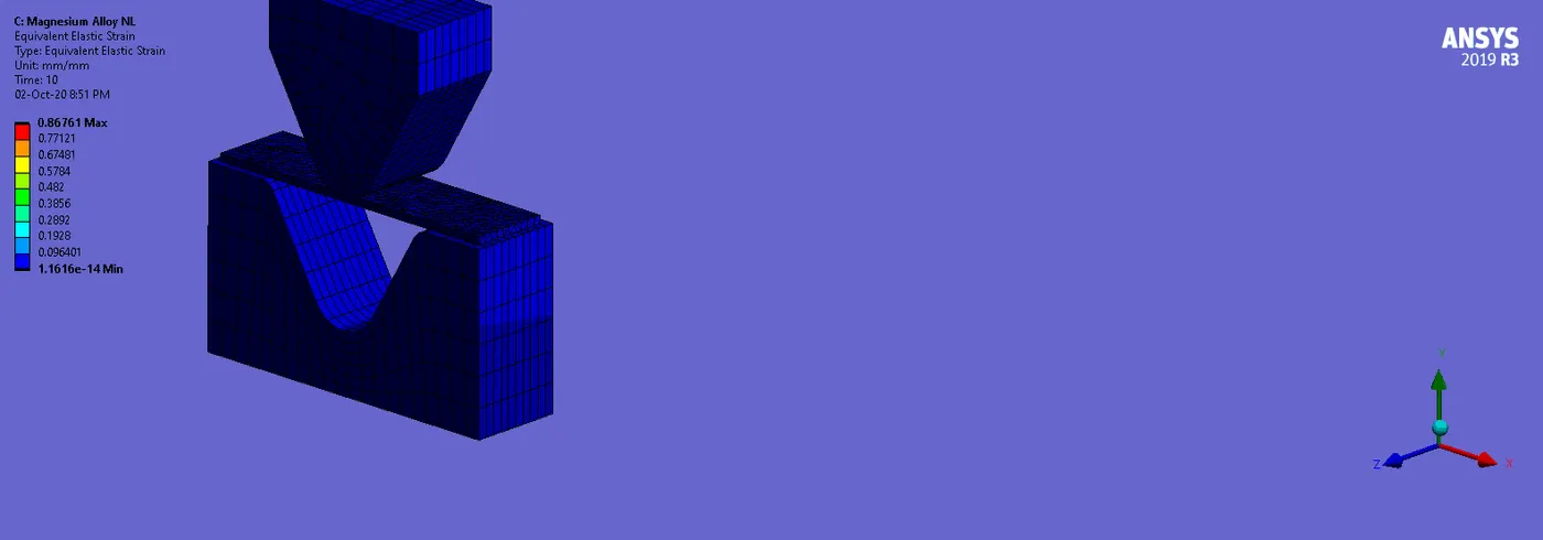
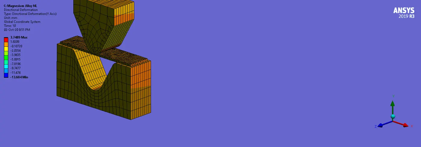
Case_3: Magnesium Alloy NL
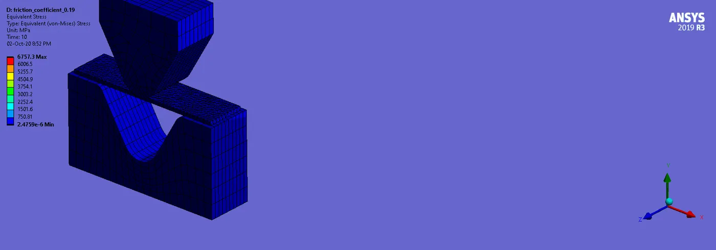
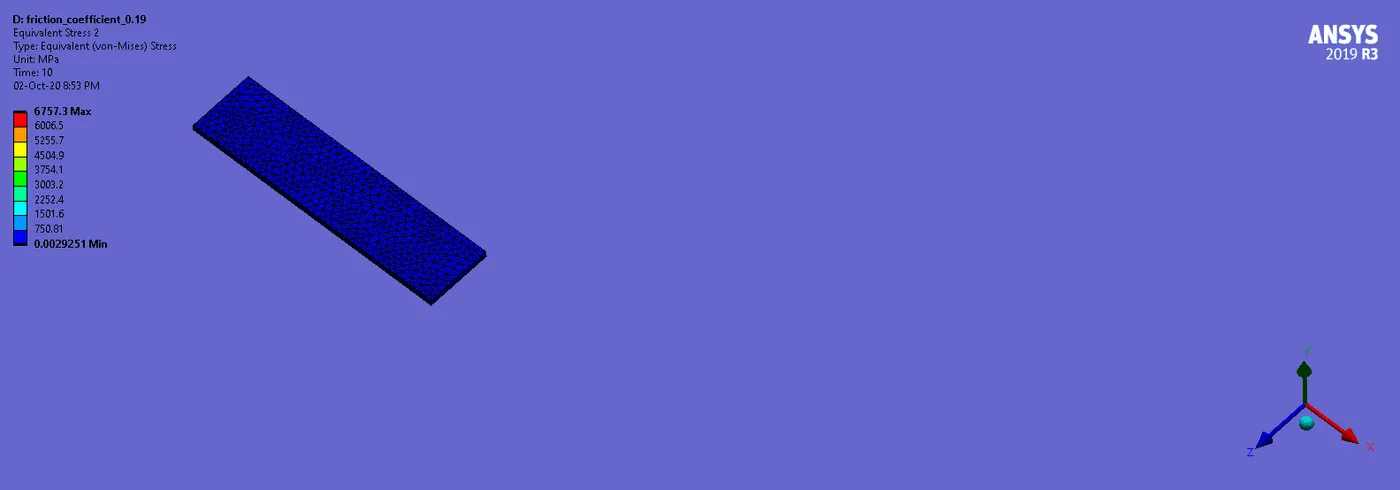
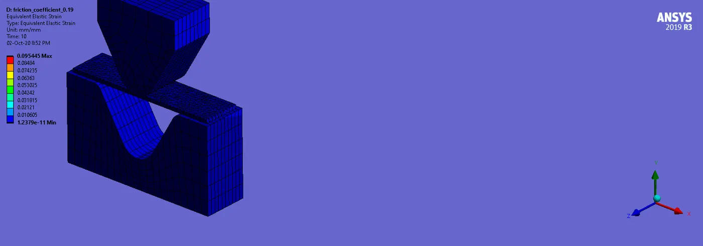
Case_4: Aluminium Alloy with Friction Coefficient 0.19
Case_5: Aluminium Alloy with Mesh Refinement
________________________________________________________________________________________________________________________
Geometry:
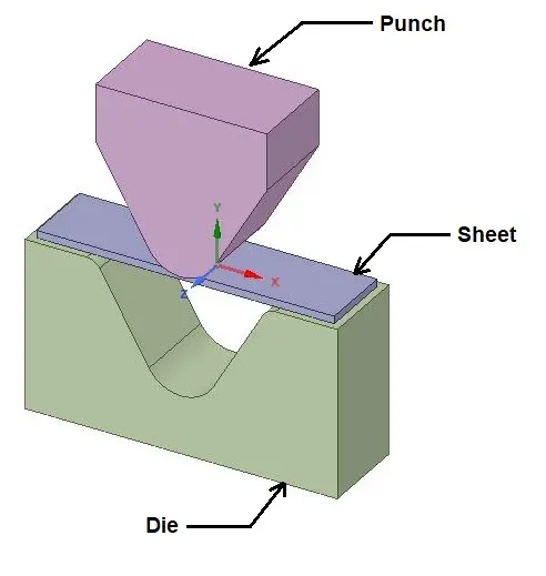
- There are three parts in this setup.
- As per above image, parts in this setup are Punch, Sheet and Die.
________________________________________________________________________________________________________________________
Material:
Material Specifications for CASE_1:
Aluminium Alloy 1199
Density: 2770 Kg/m3
Young’s Modulus: 62000 MPa
Poisson’s Ratio: 0.33
Yield Strength: 140 MPa
Tangent Modulus: 209.46 Mpa
Material Specifications for CASE_2:
Copper Alloy NL
Density: 8300 Kg/m3
Young’s Modulus: 1.1 E+05 MPa
Poisson’s Ratio: 0.34
Yield Strength: 280 MPa
Tangent Modulus: 1150 Mpa
Material Specifications for CASE_3:
Magnesium Alloy NL
Density: 1800 Kg/m3
Young’s Modulus: 45000 MPa
Poisson’s Ratio: 0.35
Yield Strength: 193 MPa
Tangent Modulus: 920 Mpa
Material Specifications for CASE_4 & 5:
Aluminium Alloy
Density: 2770 Kg/m3
Young’s Modulus: 71000 MPa
Poisson’s Ratio: 0.33
Tensile Yield Strength: 280 MPa
Tensile Ultimate Strength: 310 Mpa
________________________________________________________________________________________________________________________
Mesh:
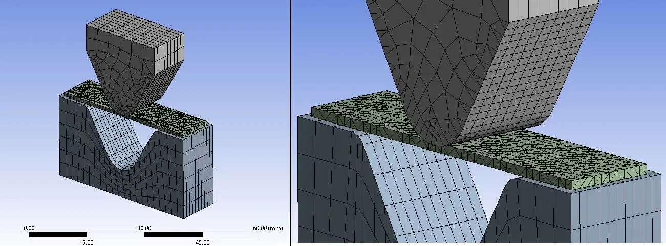
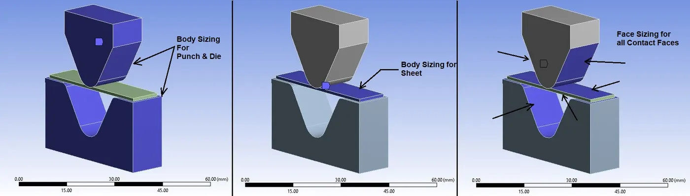
Mesh Details for CASE_1, 2, 3 & 4:
- Global Size: Default
- Body Sizing: 4 mm (For Punch & Die)
- Body Sizing: 1 mm (For Sheet)
- Face Sizing: 1 mm (For All Contact Faces)
- Patch Conforming Method: Tetrahedrons
No. of Nodes: 18058
No. of Elements: 6256
Mesh Details for CASE_5:
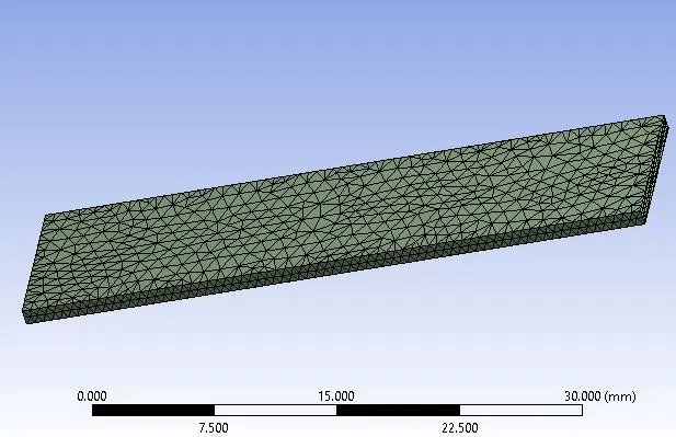
- All settings are same as other cases.
- Body Sizing: 0.55 mm (For Sheet)
No. of Nodes: 28945
No. of Elements: 13692
________________________________________________________________________________________________________________________
Procedure:
- Import model in Static Structural named as “Skill_lync_Al_Sheet_Bending.x_t” in Geometry section.
- Then go to Mechanical model section.
- Check or Rename the Parts of the setup as “Punch” , Sheet” and “Die” as shown in above geometry image.
Connections:
- Delete automatically created contacts and create new contacts as given below:
Contact_1:
Contact Body = Punch
Target Body = Sheet
Contact_2:
Contact Body = Sheet
Target Body = Die
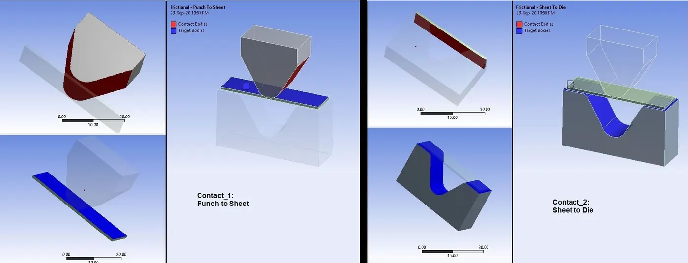
- Here in above image, we can see the contacts as “Punch to Sheet” and “Sheet to Die”.
Settings for Both Contacts:
Type: Frictional
Friction Coefficient: 0.1
Behavior: Auto Asymmetric
Formulation: Augmented Lagrange
Normal Stiffness Factor: 0.1
Interface Treatment: Add Offset, Ramped Effects
- After creating contacts, generate mesh as per case discussed in above mesh section.
- Keep analysis settings as given below:
Boundary Conditions:
- After meshing as described above, create Boundary Conditions as given below:
Analysis Settings:
- No.of Steps: 6
- Auto Time Stepping : Program Controlled
- Solver Type: Direct
- Large Deflection: ON
- Non Linear Controls: Stabilization = Constant
Method = Energy
Energy Dissipation Ratio = 0.1
- Now we want to bend the Sheet with help of Punch in the Die.
So we have to give different displacements in order to move or restrict the movement in some direction of parts.
Displacement_1:
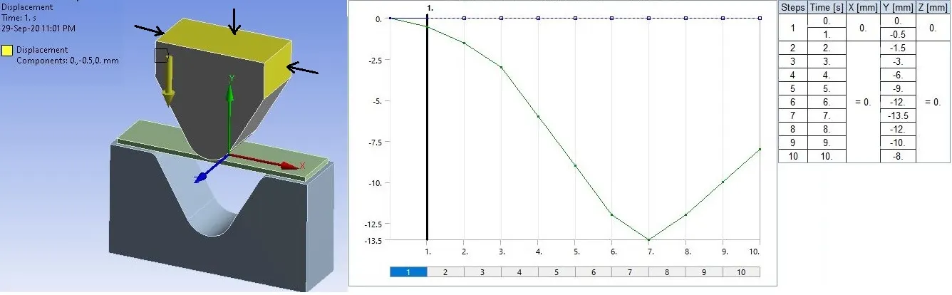
- This is the movement of punch only in Y-Direction.
Displacement_2:
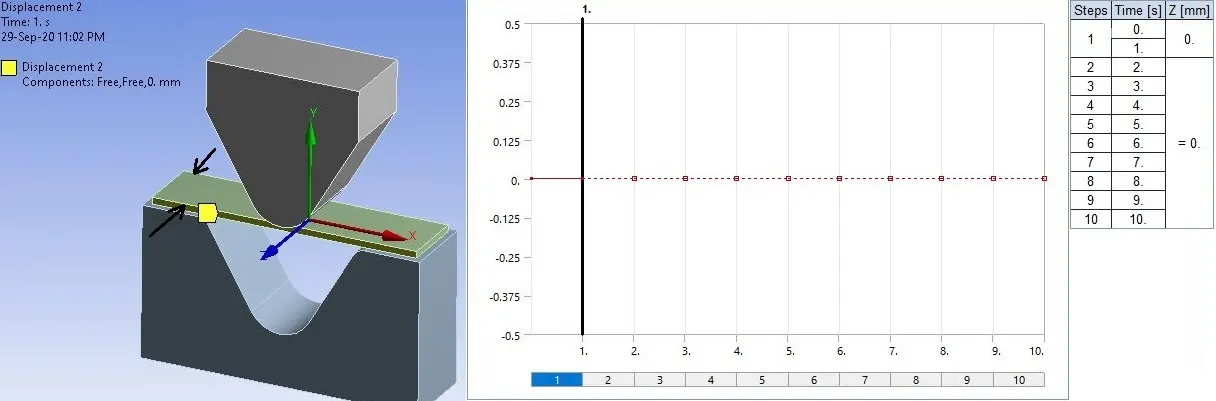
- This is the restriction of movement for Sheet in Z-Direction.
Displacement_3:
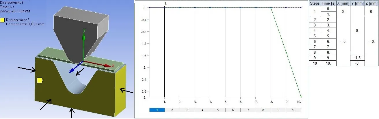
- This is the movement of Die in Y-Direction in last two steps.
Solution:
- After giving proper boundary conditions, create desired solutions for output results.
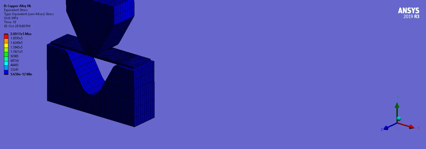
- Create Solutions for “Equivalent (Von Mises) Stress”.
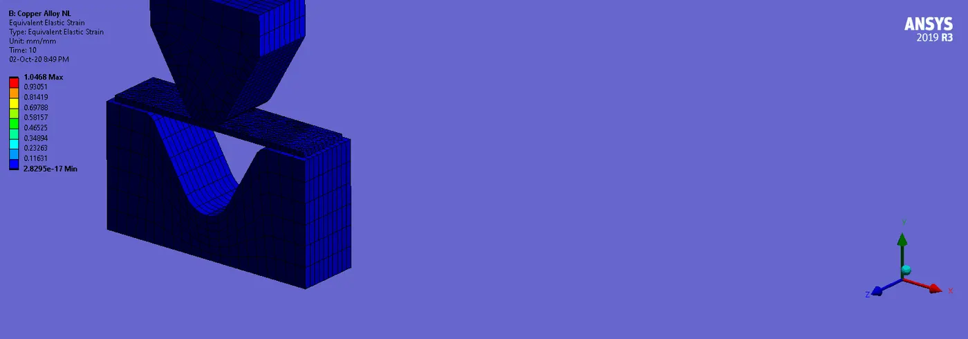
- Create Solutions for “Equivalent (Von Mises) Strain”.
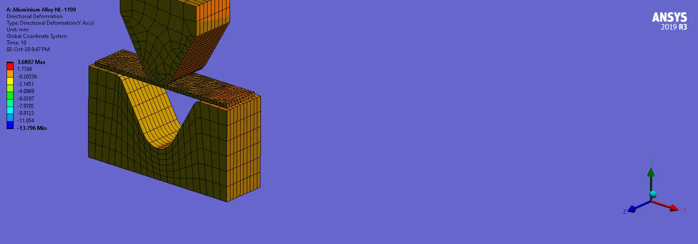
- Create Solutions for “Directional Deformation” and give orientation to Y-Direction for results.
- Solve or Evaluate for solutions.
________________________________________________________________________________________________________________________
Results:
- Now we will see all results with comparison.
Comparison of CASE_1, CASE_2 AND CASE_3:
First of all we will see the results and comparison of Aluminium Alloy 1199, Copper Alloy NL and Magnesium Alloy NL.
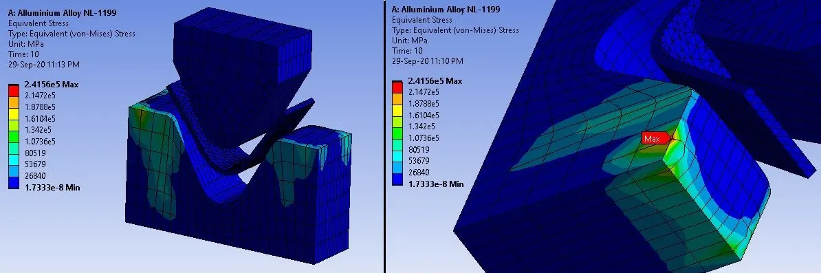
Stress Contours for Aluminium Alloy 1199:
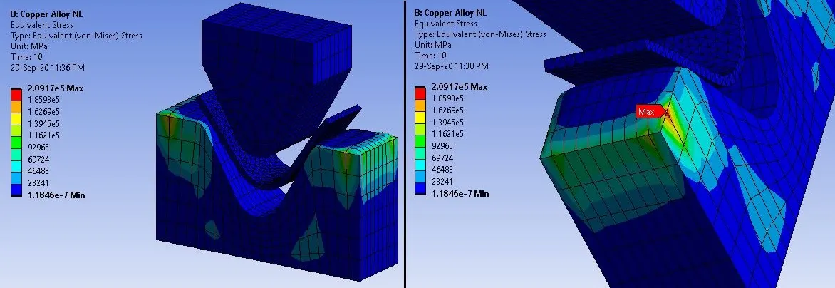
Stress Contours for Copper Alloy NL:
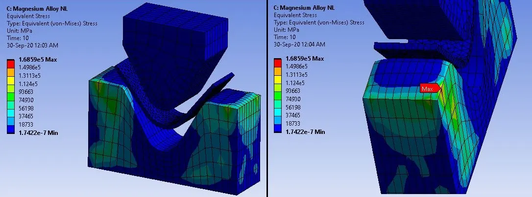
Stress Contours for Magnesium Alloy NL:
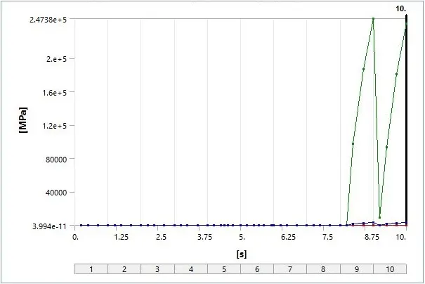
Stress Plot for Aluminium Alloy 1199:
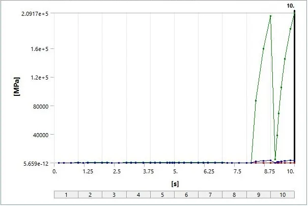
Stress Plot for Copper Alloy NL:
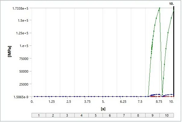
Stress Plot for Magnesium Alloy NL:
Stress Data for Aluminium Alloy 1199, Copper Alloy NL and Magnesium Alloy NL:
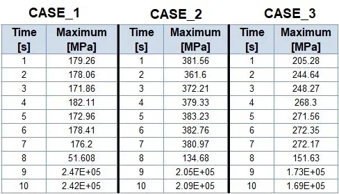
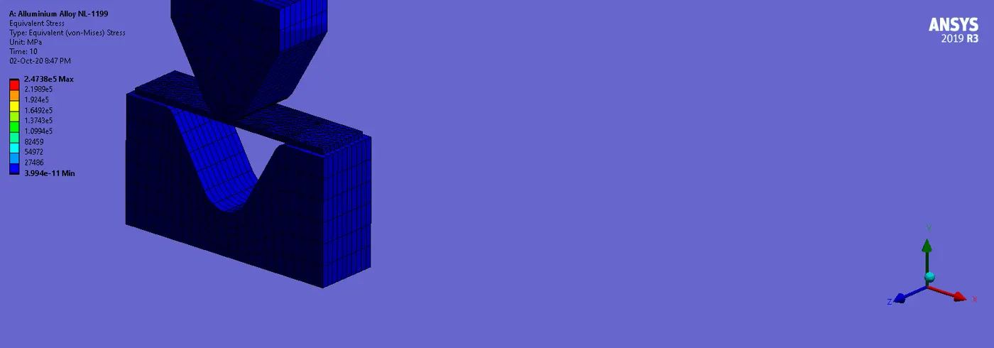
- From the contours, and plots, we can see the maximum stress develops in the Die.
- Also we can see that these stresses are inducing due to removal of load from the Punch, which is noticeable in the last two steps of plot.
- Due to Non-Linear material the stress in the sheet is lower compared to Die.
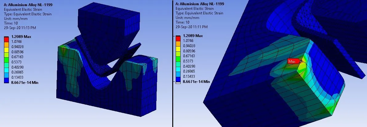
Strain Contours for Aluminium Alloy 1199:
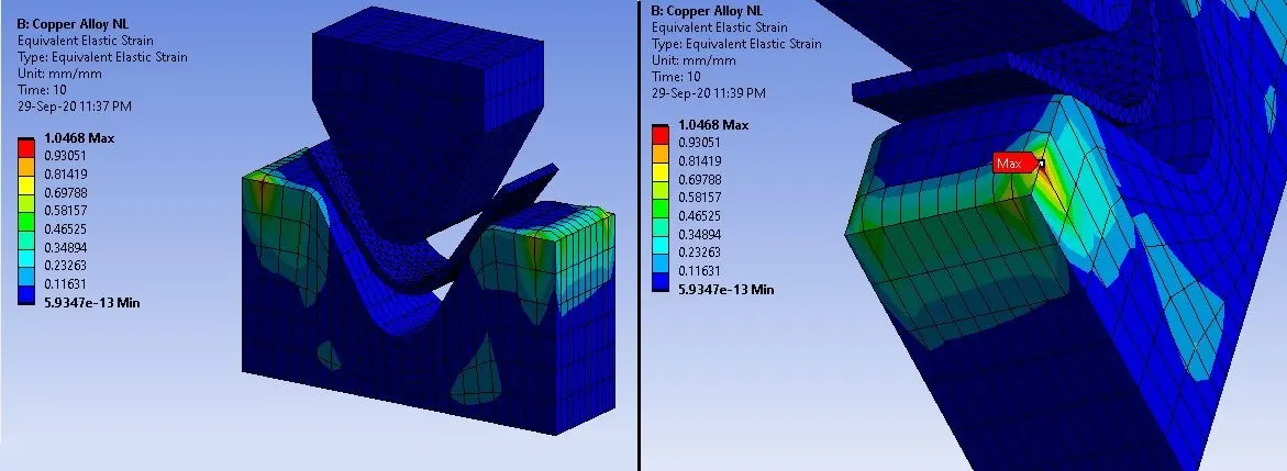
Strain Contours for Copper Alloy NL:
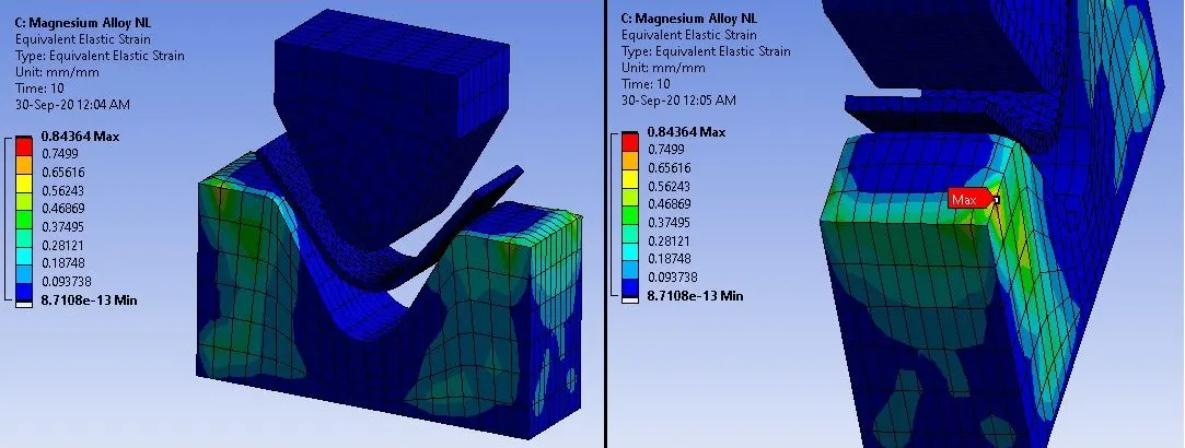
Strain Contours for Magnesium Alloy NL:
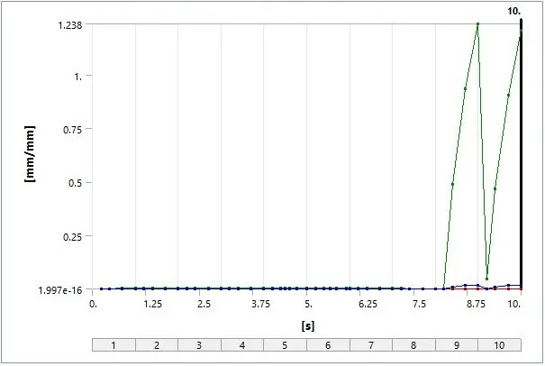
Strain Plot for Aluminium Alloy 1199:
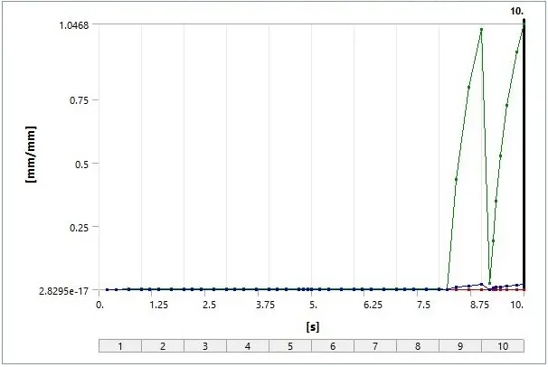
Strain Plot for Copper Alloy NL:
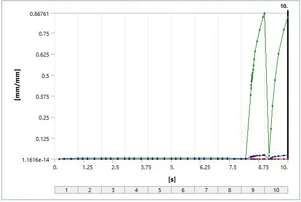
Strain Plot for Magnesium Alloy NL:
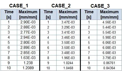
Strain Data for Aluminium Alloy 1199, Copper Alloy NL and Magnesium Alloy NL:
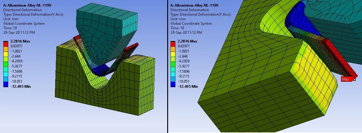
Deformation Contours for Aluminium Alloy 1199:
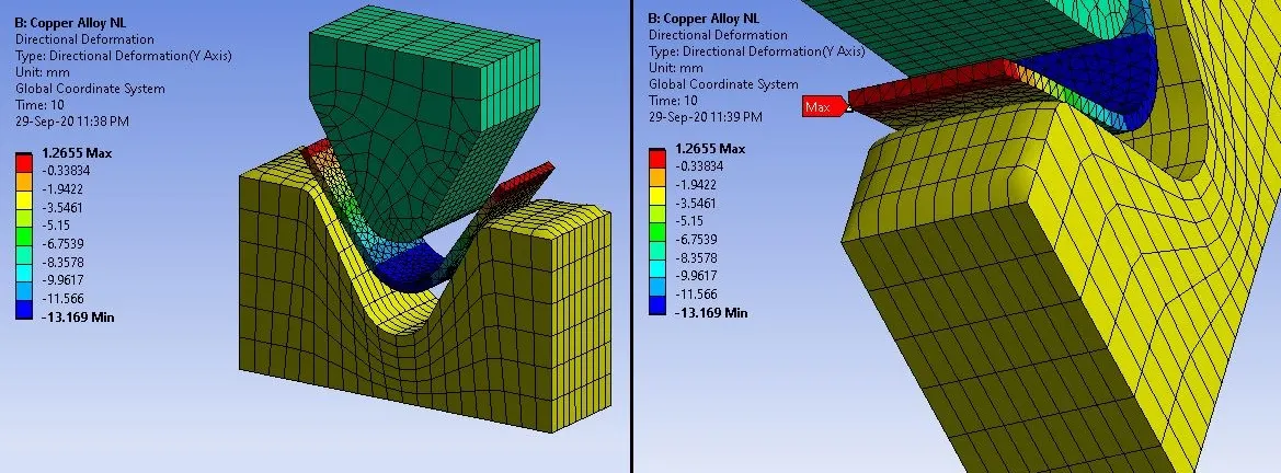
Deformation Contours for Copper Alloy NL:
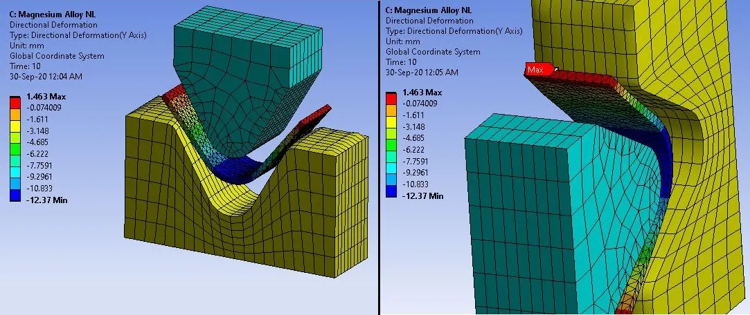
Deformation Contours for Magnesium Alloy NL:
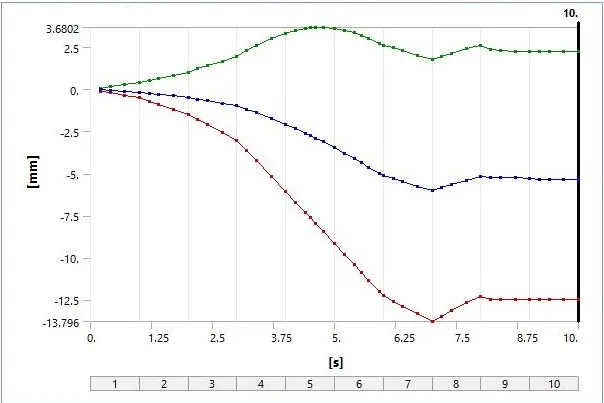
Deformation Plot for Aluminium Alloy 1199:
Deformation Plot for Copper Alloy NL:
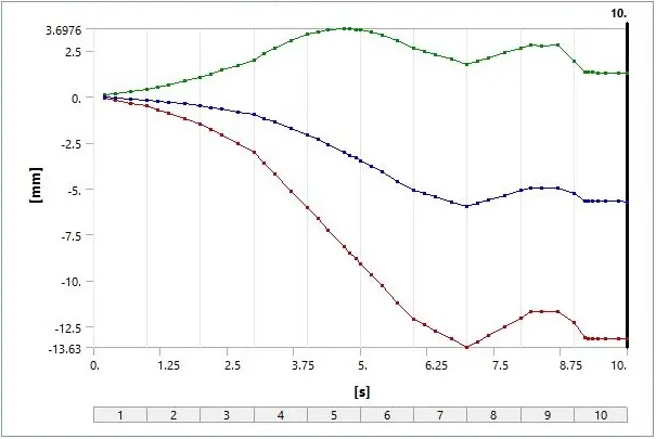
Deformation Plot for Magnesium Alloy NL:
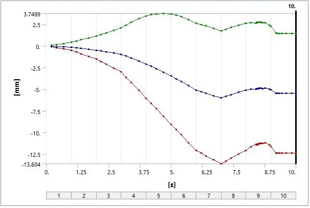
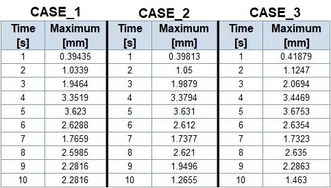
- Maximum deformation is observed at the end portion of the sheet, which is due to large displacement.
Deformation Data for Aluminium Alloy 1199, Copper Alloy NL, and Magnesium Alloy NL:
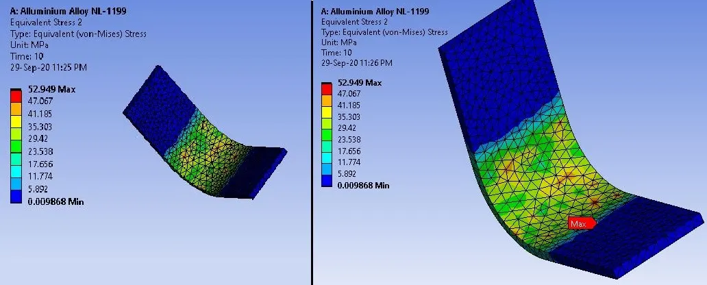
Stress Contours for Aluminium Alloy 1199 Sheet:
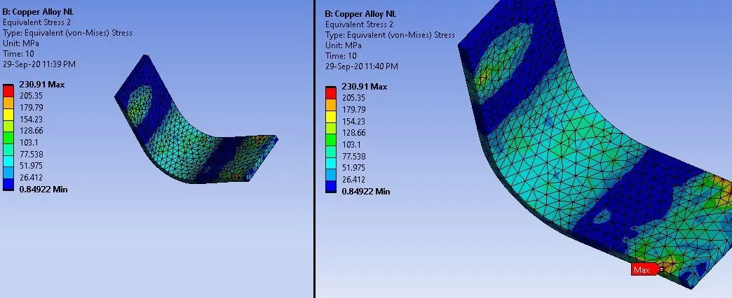
Stress Contours for Copper Alloy NL Sheet:
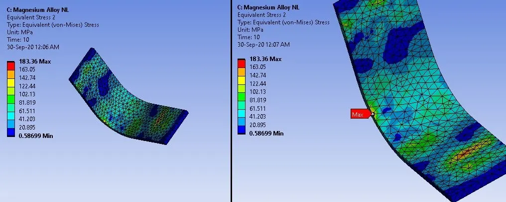
Stress Contours for Magnesium Alloy NL Sheet:
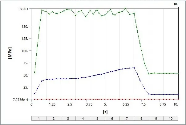
Stress Plot for Aluminium Alloy 1199 Sheet:
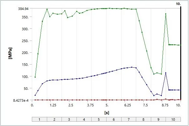
Stress Plot for Copper Alloy NL Sheet:
Stress Plot for Magnesium Alloy NL Sheet:
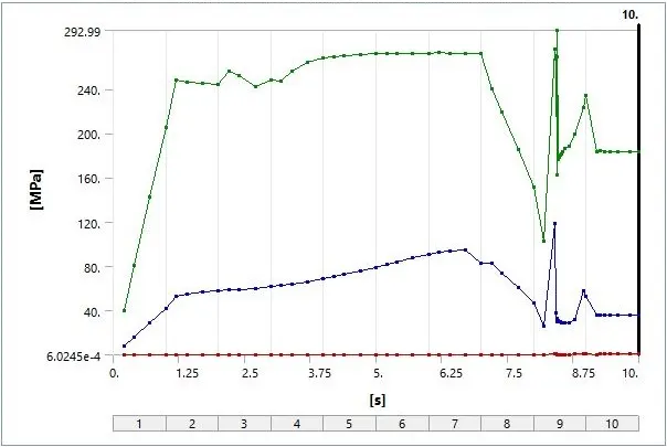
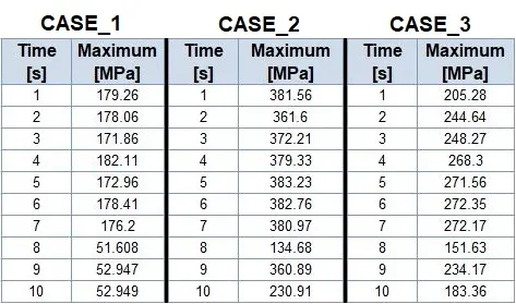
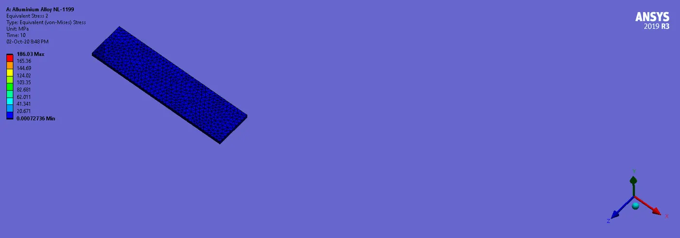
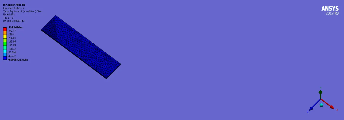
- As per above results of stress , we can see that maximum stress in Aluminium alloy 1199 is 52.949 Mpa, which is less than Copper Alloy NL and Magnesium Alloy NL.
- Also in CASE_1, stress is concentrated at middle portion and in CASE_2 and CASE_3; stress is distributed over entire plate.
- Also plot of Aluminium Alloy 1199 Sheet is becoming stable after 7.5 s. So after that stress is becoming stable and we can see the plastic deformation. But in case of Copper Alloy NL and Magnesium Alloy NL, we can see hikes in plots, which can be due to spring back effect.
Stress Data for Aluminium Alloy 1199, Copper Alloy NL and Magnesium Alloy NL Sheets:
_ _ _ _ _ _ _ _ _ _ _ _ _ _ _ _ _ _ _ _ _ _ _ _ _ _ _ _ _ _ _ _ _ _ _ _ __ _ _ _ _ _ _ _ _ _ _ _ _ _ _ _ __ _ _ _ __ _ _ _ _ _ _ _ _ _ _ _ _ _ __ _ _ _ _ _ _
Comparison of CASE_1 AND CASE_4:
Now we will see the results and comparison of Aluminium Alloy 1199 and Aluminium Alloy (with Coefficient of friction = 0.19):
Stress Contours:
Stress Plot:
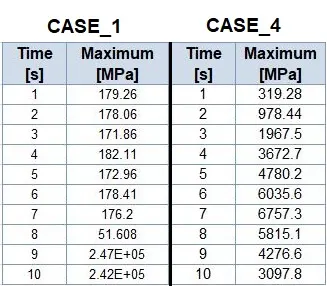
Stress Data:
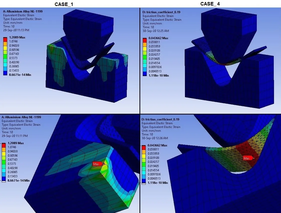
Strain Contours:
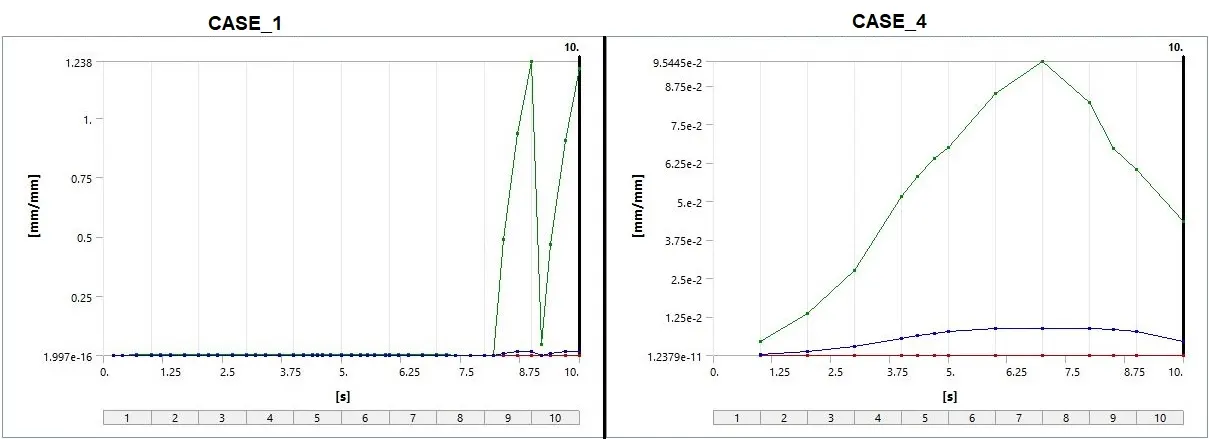
Strain Plot:
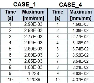
Strain Data:
Deformation Contours:
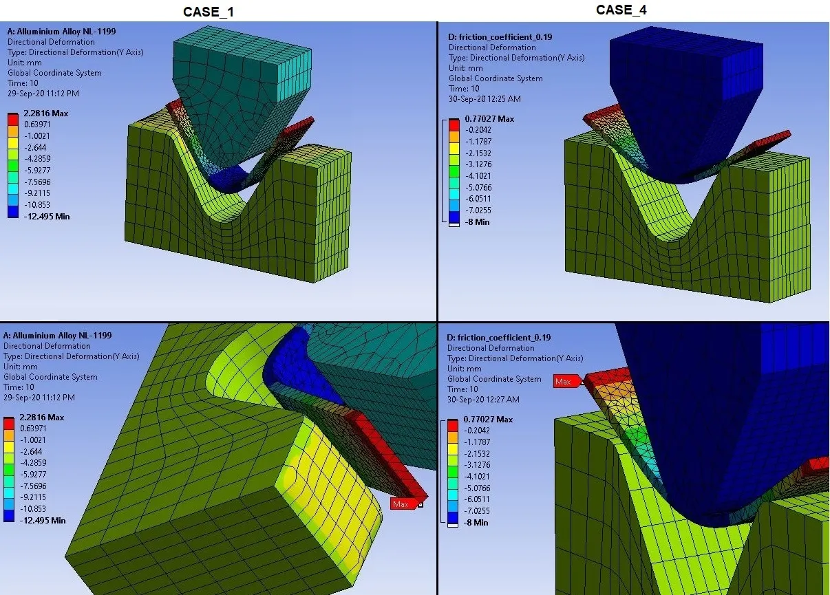
Deformation Plot:
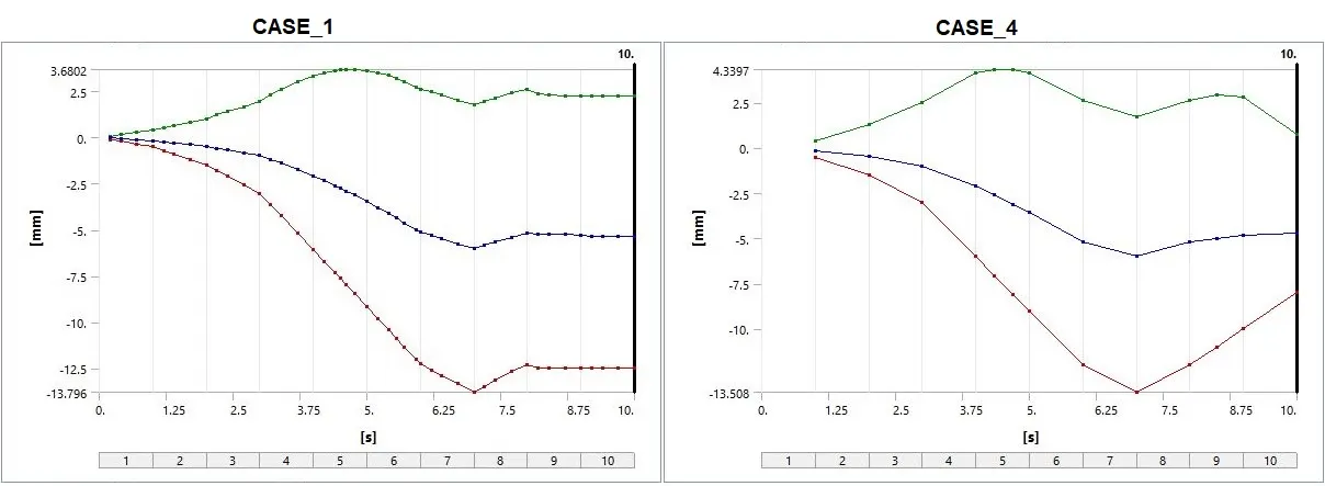
Deformation Data:
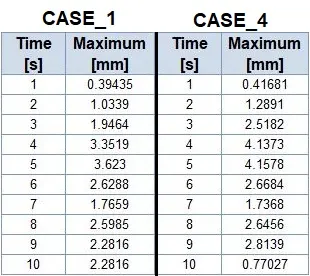
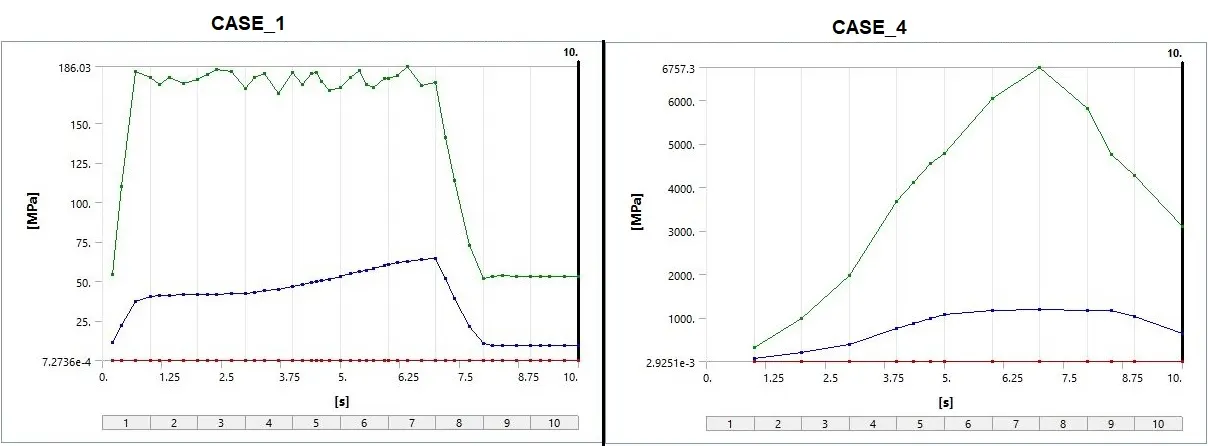
Stress Contours for Sheet:
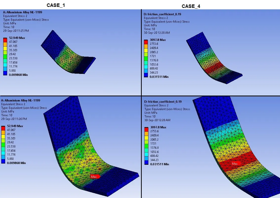
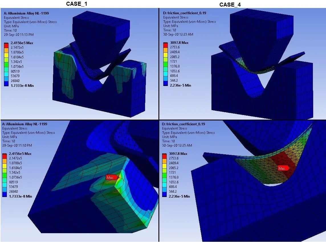
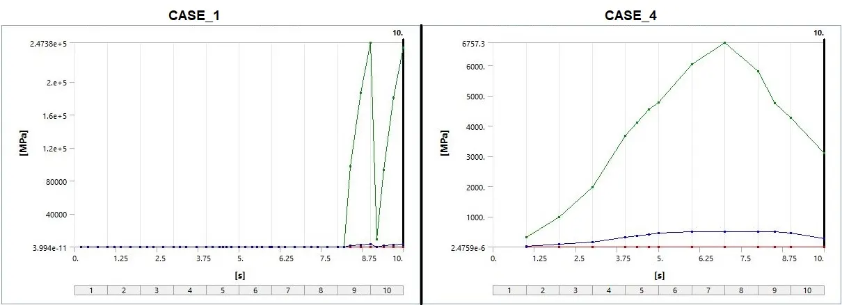
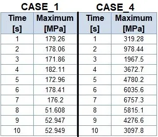
- Here we can see the stress is high in sheet in CASE_1 compared to CASE_1.
- This effect is due to increased friction coefficient from 0.1 to 0.19.
- As coefficient of friction increases, load for punching the sheet will also increases. And due to that, we can observe high stress in sheet.
Stress Plot for Sheet:
Stress Data for Sheet:
_ _ _ _ _ _ _ _ _ _ _ _ _ _ _ _ _ _ _ _ _ _ _ _ _ _ _ _ _ _ _ _ _ _ _ _ __ _ _ _ _ _ _ _ _ _ _ _ _ _ _ _ __ _ _ _ __ _ _ _ _ _ _ _ _ _ _ _ _ _ __ _ _ _ _ _ _
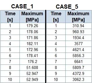
Comparison of CASE_1 AND CASE_5:
Now we will see the results and comparison of Aluminium Alloy 1199 and Aluminium Alloy (with Refined Mesh):
Stress Contours:
Stress Plot:
Stress Data:
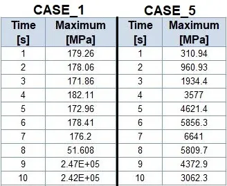
Strain Contours:
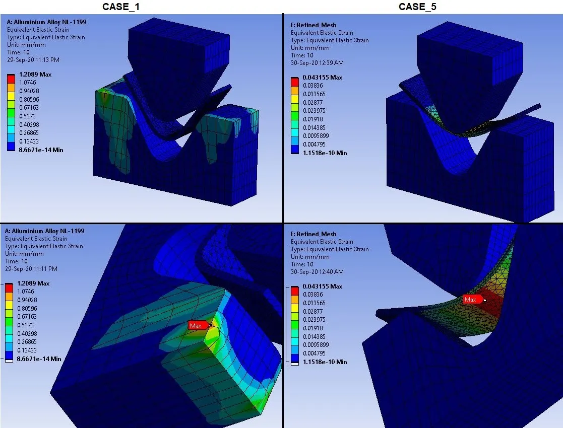
Strain Plot:
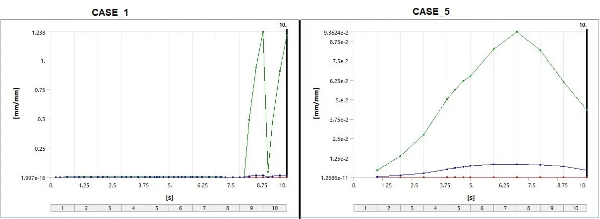
Strain Data:

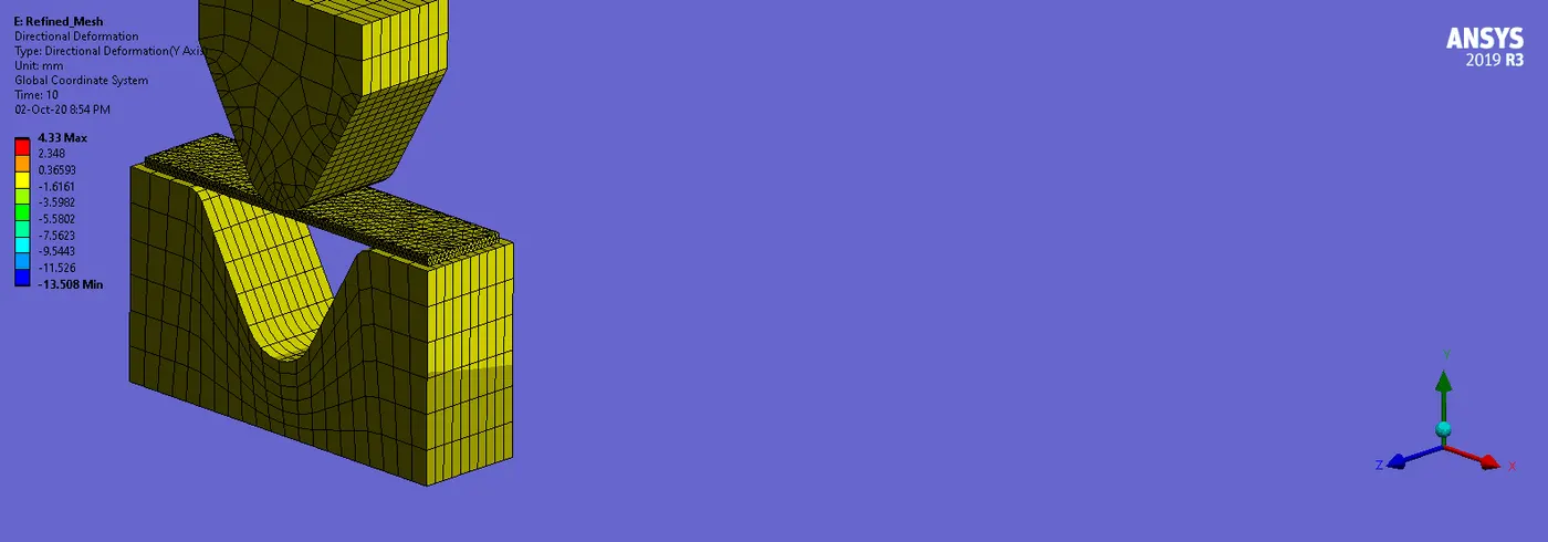
Deformation Contours:
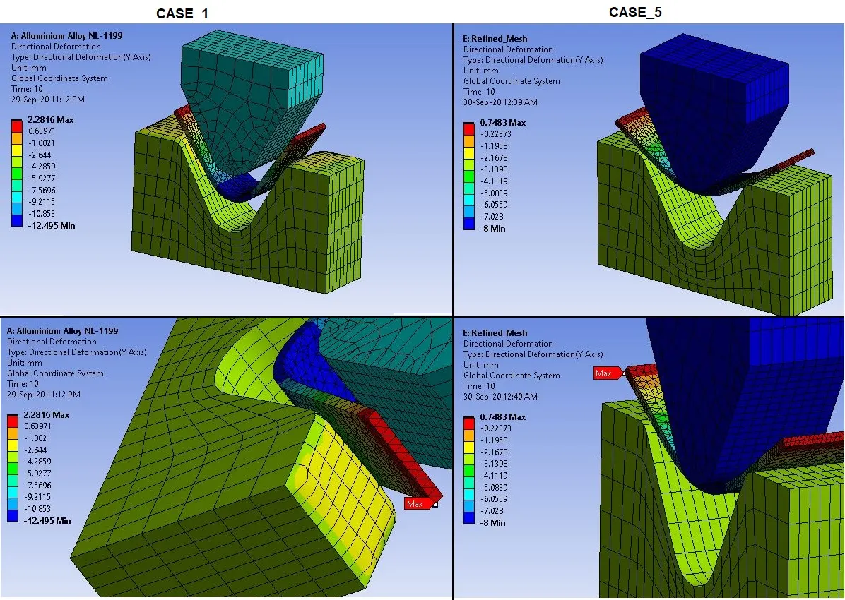
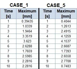
Deformation Plot:
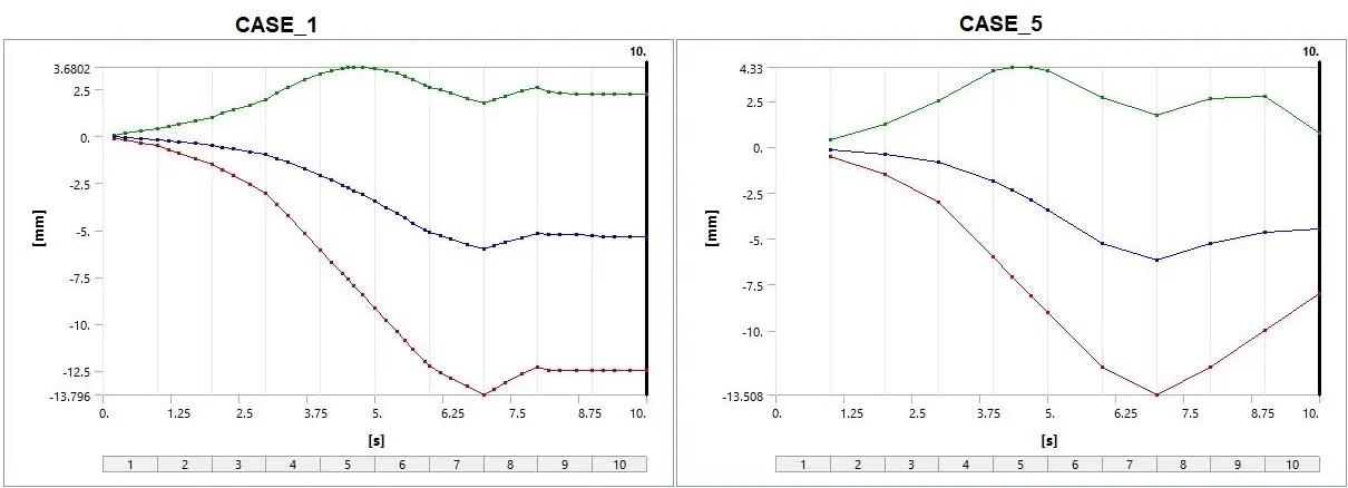
Deformation Data:
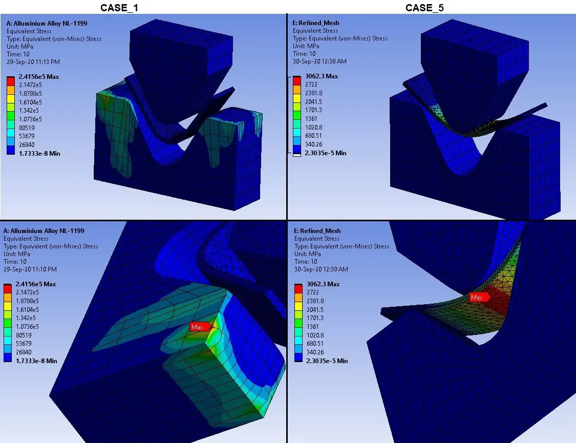
Stress Contours for Sheet:
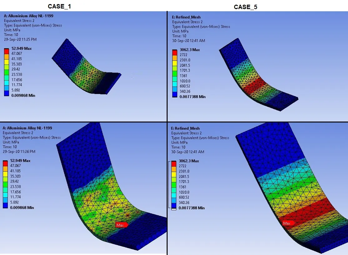
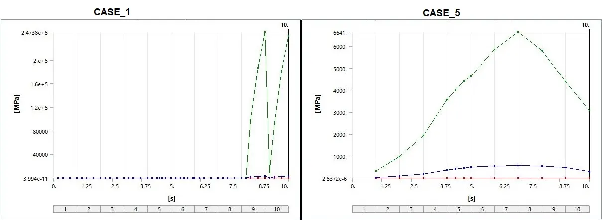
- As in CASE_4 we can observe higher stress values in sheet compared to CASE_1.
- This result gives more accuracy due to refinement of Mesh.
- As higher the refinement of mesh, higher the accuracy of the result.
- Also in CASE_5, material we have used is Aluminium Alloy. This has higher value of Young’s Modulus. And as the Young’s Modulus is higher, stress strain ratio will be higher. So the Value of stress is also higher in CASE_5.
Stress Plot for Sheet:
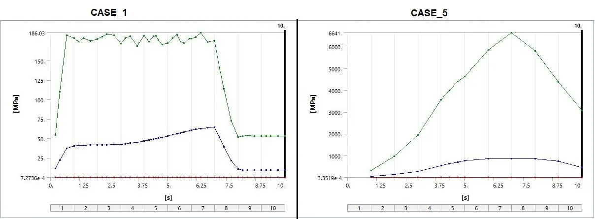
Stress Data for Sheet:
________________________________________________________________________________________________________________________
Conclusion:
- Sheet metal bending process is most effective in ductile material such as Aluminium, copper etc.
- This process also considers the plastic deformation. So the stress would be higher.
- Depending on the stress concentration and properties of material, bending accuracy can be different.
- As we observed in CASE_1, 2 and 3, among which in CASE_1, with Aluminium Alloy 1199 has stress concentration in the middle portion can be noticed. This helps bending more efficient way.
- Also from the plots, we can observe that there can be an effect of spring break.
- From the comparison of CASE_1 & CASE_4, we can conclude that Aluminium Alloy with Coefficient of friction 0.19 give better results than Aluminium Alloy 1199. Because it has higher Young’s Modulus and it can give Elastic-Plastic behavior.
- Also from the comparison of CASE_1 and CASE_5, we can observe that Aluminium Alloy gives better results as there is a higher stress. We can see perfect stress distribution and good bending behavior due to refined mesh.
- If we compare results of Aluminium Alloy with Friction coefficient 0.19 and with Friction coefficient 0.1, we can observe from CASE_4 and CASE_5, that results are very close in both cases.
- Also Aluminium is the most used material for metal forming. So from above all results, we can conclude that Aluminium Alloy is best suited material for Sheet Metal Bending Process.
________________________________________________________________________________________________________________________
References:
- https://en.wikipedia.org/wiki/Bending_(metalworking)
- https://thelibraryofmanufacturing.com/sheetmetal_bending.html
- https://www.sv-jme.eu/?ns_articles_pdf=/ns_articles/files/ojs/383/public/383-3603-1-PB.pdf&id=2938
- https://www.rroij.com/open-access/sheet-metal-forming-analyses-with-springbackdeformation-on-ubends-in-isotropic-plates.pdf
- http://ceb.ac.in/knowledge-center/E-BOOKS/Mechanics%20of%20Sheet%20Metal%20Forming%20-%20Marciniak.pdf
- https://www.smlease.com/entries/sheet-metal-design/sheet-metal-materials/
- https://www.scielo.br/scielo.php?script=sci_arttext&pid=S1678-58782011000100007
- https://web.s-cdn.boostkit.dev/webactions/591c7ba1ee786d2050cb7421_events/module_sheet_metal-59833965ee786c72ac58f7e9-59ad3ba23872832324570ac5.pdf
- https://www.custompartnet.com/wu/sheet-metal-forming
________________________________________________________________________________________________________________________
Animations:
CASE_1 (ALUMINIUM ALLOY 1199):
STRESS:
STRESS ON SHEET:
STRAIN:
TOTAL DEFORMATION IN Y-DIRECTION:
_ _ _ _ _ _ _ _ _ _ _ _ _ _ _ _ _ _ _ _ _ _ _ _ _ _ _ _ _ _ _ _ _ _ _ _ _ _ _ _ _ _ _ _ _ _ _ _ _ _ _ __ _ _ _ _ _ _ _ _ _ _ _ _ _ _ _ _ _ _ _ _ _ _ _ _ _ _ _
CASE_2 (COPPER ALLOY NL):
STRESS:
STRESS ON SHEET:
STRAIN:
TOTAL DEFORMATION IN Y-DIRECTION:
_ _ __ _ _ _ _ _ _ _ _ _ _ _ _ _ _ _ _ _ _ _ _ _ _ _ _ _ _ _ _ _ _ _ _ _ _ _ _ _ _ _ _ _ _ _ _ _ _ _ __ _ _ _ _ _ _ _ _ _ _ _ _ _ _ _ _ _ _ _ _ _ _ _ _ _ _ _
CASE_3 (MAGNESIUM ALLOY ALLOY NL):
STRESS:
STRESS ON SHEET:
STRAIN:
TOTAL DEFORMATION IN Y-DIRECTION:
_ _ _ _ _ _ _ _ _ _ _ _ _ _ _ _ _ _ _ _ _ _ _ _ _ _ _ _ _ _ _ _ _ _ _ _ _ _ _ _ _ _ _ _ _ _ _ _ _ _ _ __ _ _ _ _ _ _ _ _ _ _ _ _ _ _ _ _ _ _ _ _ _ _ _ _ _ _ _
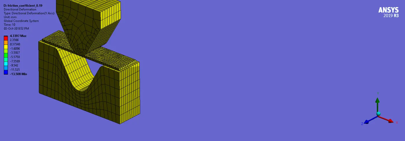
CASE_4 (ALUMINIUM ALLOY , WITH FRICTION COEFFICIENT = 0.19):
STRESS:
STRESS ON SHEET:
STRAIN:
TOTAL DEFORMATION IN Y-DIRECTION:
_ _ _ _ _ _ _ _ _ _ _ _ _ _ _ _ _ _ _ _ _ _ _ _ _ _ _ _ _ _ _ _ _ _ _ _ _ _ _ _ _ _ _ _ _ _ _ _ _ _ _ __ _ _ _ _ _ _ _ _ _ _ _ _ _ _ _ _ _ _ _ _ _ _ _ _ _ _ _
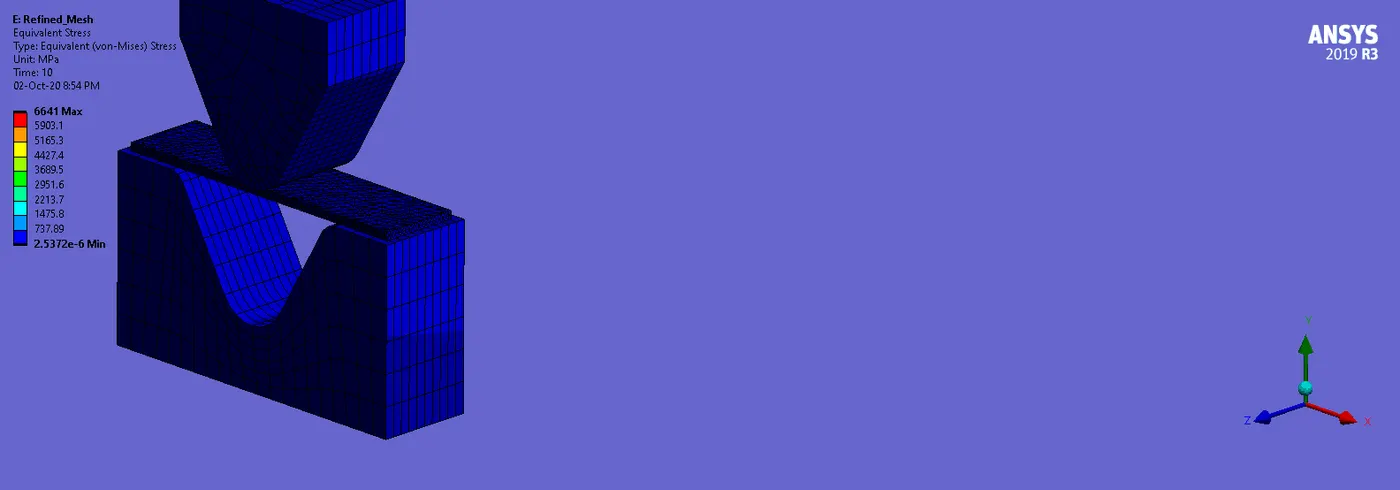
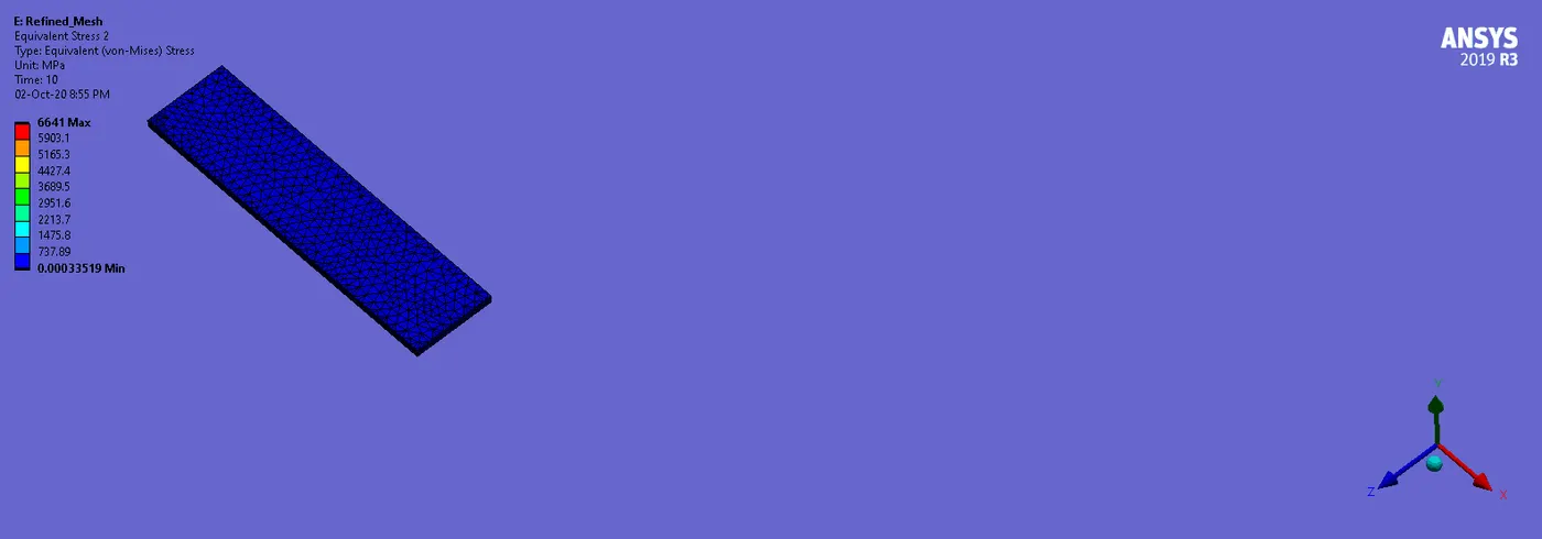
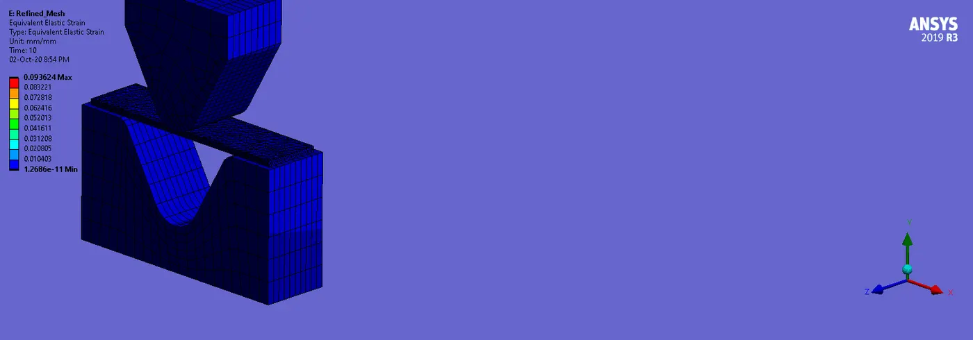
CASE_5 (ALUMINIUM ALLOY , WITH REFINED MESH):
STRESS:
STRESS ON SHEET:
STRAIN:
TOTAL DEFORMATION IN Y-DIRECTION:
________________________________________________________________________________________________________________________
Thanks & Regards,
Dharmesh Joshi