Week 8 Worm Gear Challenge

Introduction:
A worm drive is a gear arrangement in which a worm (which is a gear in the form of a screw) meshes with a worm gear (which is similar in appearance to a spur gear). The two elements are also called the worm screw and worm wheel. The terminology is often confused by imprecise use of the term worm gear to refer to the worm, the worm gear, or the worm drive as a unit.
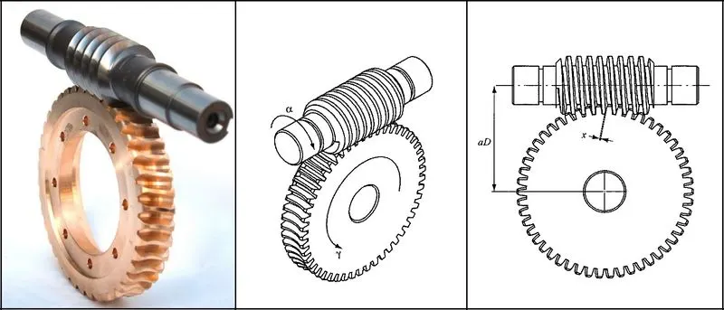
The worm gear or "endless screw" was invented by either Archytas of Tarentum, Apollonius of Perge, or Archimedes, the last one the most probable author. The worm gear later appeared in the Indian subcontinent, for use in roller cotton gins, during the Delhi Sultanate in the thirteenth or fourteenth centuries.
Like other gear arrangements, a worm drive can reduce rotational speed or transmit higher torque. A worm is an example of a screw, one of the six simple machines. One of the major advantages of worm gear drive units is that they can transfer motion in 90 degrees. The worm in the worm gear drive may have single or multiple starts. Each full 360 degree turn of a single start worm advances the gear by one tooth. For a multi start worm the gear reduction equals the number of teeth on the gear divided by the number of starts on the worm. Both the sliding and the rolling actions of the worm and the gear come into play during the meshing of the gears. The sliding contact dominates at high reduction ratios. Much heat is produced due to friction while sliding, which limits the efficiency of worm gears to 30 to 90 percent. The worm and the gear are made of dissimilar metals in order to minimize the friction and loss in efficiency.
Worm gear drives are an established part of the used transmission concepts in the drive train sector. They are used as power transmissions, e.g. in escalators, elevators, and conveyor belts as well as servo-drives in precision applications. In these applications, the advantages of a high transmission ratio in small installation space, low-noise operation, and the possibility of self-breaking and self-locking outweigh the disadvantages of reduced efficiency.
_____________________________________________________________________________________________________________________
Analysis:
- Here we will see the Transient Structural Analysis of Worm Gear, in which there is an assembly of a Worm and Worm gear.
- We will apply the rotation to the Worm and check the deformation, stress etc on transmission of motion from Worm to Worm gear.
- We will track the motion of the Worm and Worm gear with time and see the behavior of the contact and reactions.
_____________________________________________________________________________________________________________________
Geometry & Material Properties:
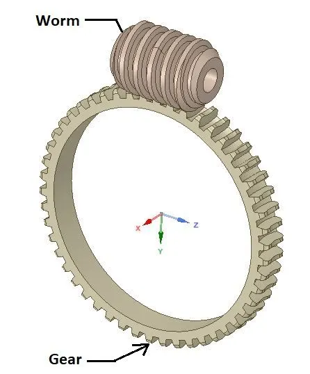
- Here the rotation will be applied to the worm and the motion of the Worm will be transmitted to the Worm gear. Worm and Worm gear are as shown in above image.
Material Specifications for CASE_1,2 &3 :
Structural Steel
Density: 7850 Kg/m3
Young’s Modulus: 2 E+05 MPa
Poisson’s Ratio: 0.3
Tensile Yield Strength: 250 Mpa
Compressive Yield Strength: 250 Mpa
Tensile Ultimate Strength: 460 Mpa
_____________________________________________________________________________________________________________________
Mesh:
Details:
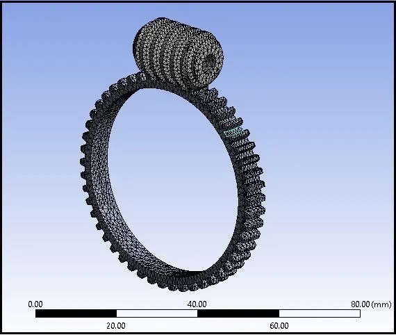
- Global Element Size: 1 mm
- Use Adaptive Sizing: Yes
- Quality: Smoothing= Medium
- Statistics:
No.of Nodes: 43203
No.of Elements: 22891
_____________________________________________________________________________________________________________________
Procedure:
- Import model in Transient Structural in Geometry section.
- Then go to Mechanical model section.
- Check or Rename the Parts of the setup as “Worm”, “Gear_Joint” and “Gear” as shown in above geometry image.
Connections:
Contacts:
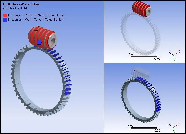
Contact_1: Worm to Gear
Type: Frictionless
Contact Body = Worm
Target Body = Gear
Joints :
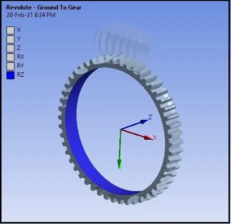
Joint_1
Connection Type: Ground to Gear
Type: Revolute
Body: Gear
Joint_2
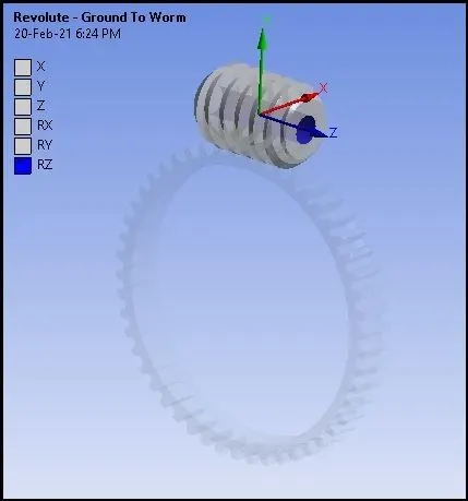
Connection Type: Ground to Worm
Type: Revolute
Body: Worm
Boundary Conditions:
- After meshing as described above, create Boundary Conditions as given below:
Analysis Settings: (For CASE_1 & CASE_2)
- No.of Steps: 15
- Solver Type: Program Controlled
- Weak Springs: Program Controlled
- Large Deflection: ON
- Auto Time Stepping: ON
- Defined By : Time
- Initial Time Step: 2 s
- Minimum Time Step: 0.2 s
- Output Controls: Stress, Strain, Contact Data, Nodal Forces, Volume & Energy, Euler Angles, General Miscellaneous etc. to Yes
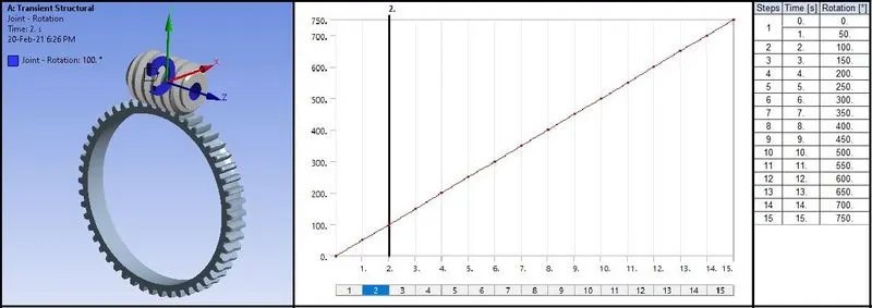
Joint Rotation:
- Apply Joint rotation to Gear at “Ground to Worm” joint in order to transform the rotary motion of the Worm to Gear.
Solution:
- After giving proper boundary conditions, create desired solutions for output results.
- Create Solutions for :
- Equivalent Stress
- Equivalent Elastic Stress
- Total Deformation
- Total Velocity for Crank
- Contact Status
- Contact Pressure
- Force Reaction
- Moment Reaction
_____________________________________________________________________________________________________________________
Results:
- Now we will see all the results for the Worm and Gear motion transmission.
Stress Contours:
Stress Plot & Data:
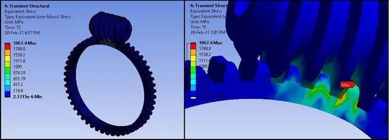
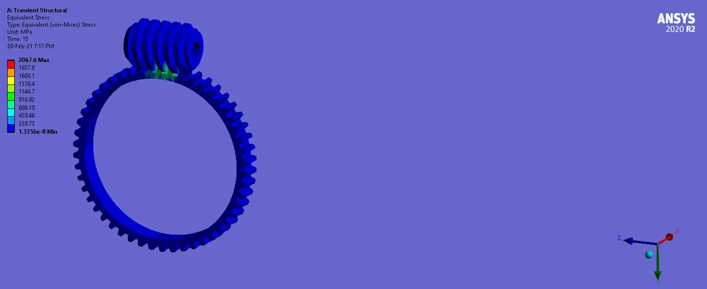
- Here from the contours, plots and data we can see that the stress on the teeth of Worm and Gear is increasing and decreasing in a cyclic form.
- Increase and decrease in the stress is nearly similar.
- The change in this type of stress graph is due to engagement and disengagement of the teeth of the Gear with the Worm.
- Stress is generating very high up to 1967.4 Mpa.
- During the transmission of the motion, higher stress is generating.
- We can see the higher stress are concentrated at the edges or contact portion of the teeth or we can say the contact faces of the Worm and Gear are facing high stress.
- Since the value of the stress is exceeding the Yield Strength of the Structural steel, it can fail.
_ _ _ _ _ _ _ _ _ _ _ _ _ _ _ _ _ _ _ _ _ _ _ _ _ _ _ _ _ _ _ _ _ _ _ _ _ _ _ _ _ _ _ _ _ _ _ _ _ _ _ _ _ _ _ _ _ _ _ _ _ _ _ _ __ _ _ _ _ _ _ _ _ _
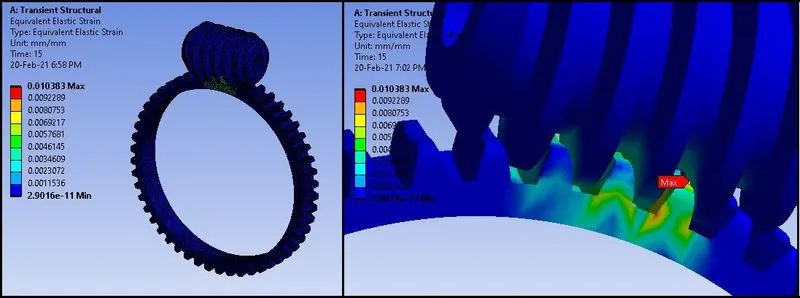
Strain Contours:
Strain Plot & Data:
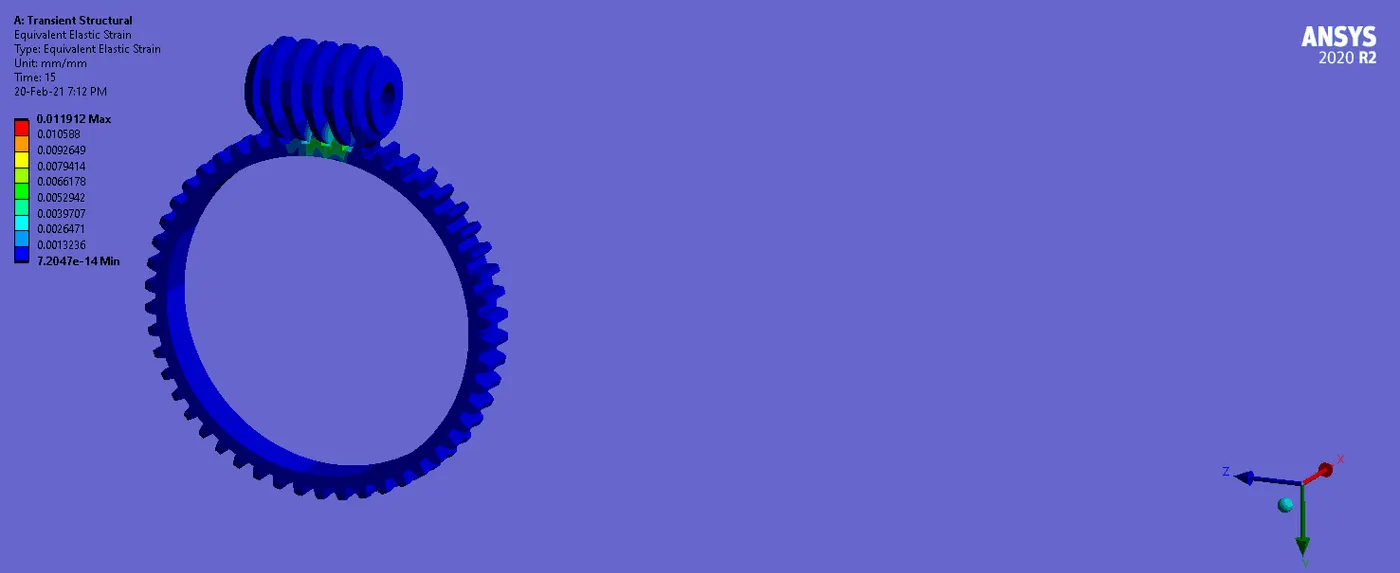
- Here we can see the Max. Strain value is 0.0104.
- Also the rate of the strain is not so high. We can see some spikes in the graph where the strain is increasing, so the amount of percentage elastic strain for failure is low.
- So the failure of the Worm or Gear Teeth is not happening at higher strain rate or due to plastic strain.
_ _ _ _ _ _ _ _ _ _ _ _ _ _ _ _ _ _ _ _ _ _ _ _ _ _ _ _ _ _ _ _ _ _ _ _ _ _ _ _ _ _ _ _ _ _ _ _ _ _ _ _ _ _ _ _ _ _ _ _ _ _ _ _ __ _ _ _ _ _ _ _ _ _
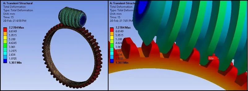
Total Deformation Contours:
Total Deformation Plot & Data:
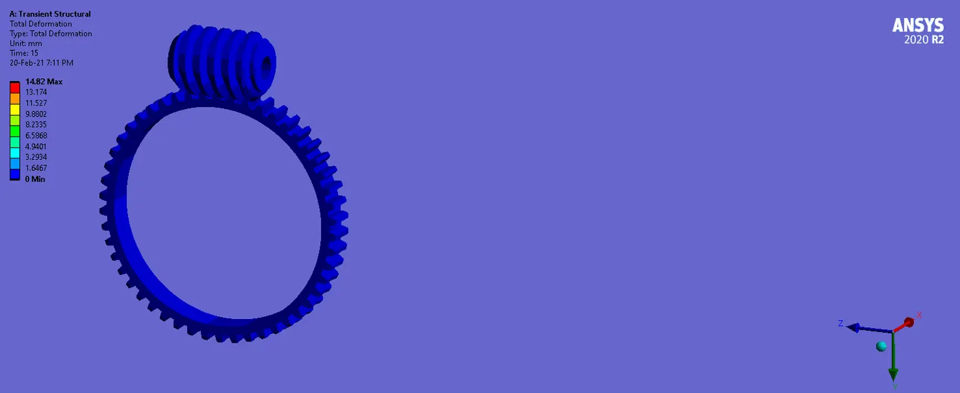
- Here we have applied the rotation to the Worm up to 15 s or up to 750 degree.
- So, the deformation will not be higher for Worm, but higher deformation will take place to the Gear, as it is big in size and for one rotation or 750 degree of the Gear, number of rotation of the Worm will be more, so the larger deformation in terms of displacement can be seen at Gear.
_ _ _ _ _ _ _ _ _ _ _ _ _ _ _ _ _ _ _ _ _ _ _ _ _ _ _ _ _ _ _ _ _ _ _ _ _ _ _ _ _ _ _ _ _ _ _ _ _ _ _ _ _ _ _ _ _ _ _ _ _ _ _ _ __ _ _ _ _ _ _ _ _ _
Contact Status Contours:
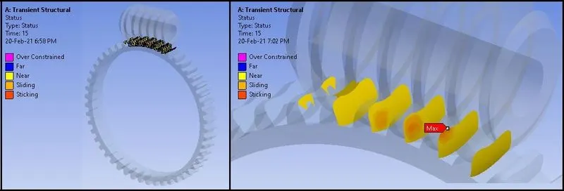
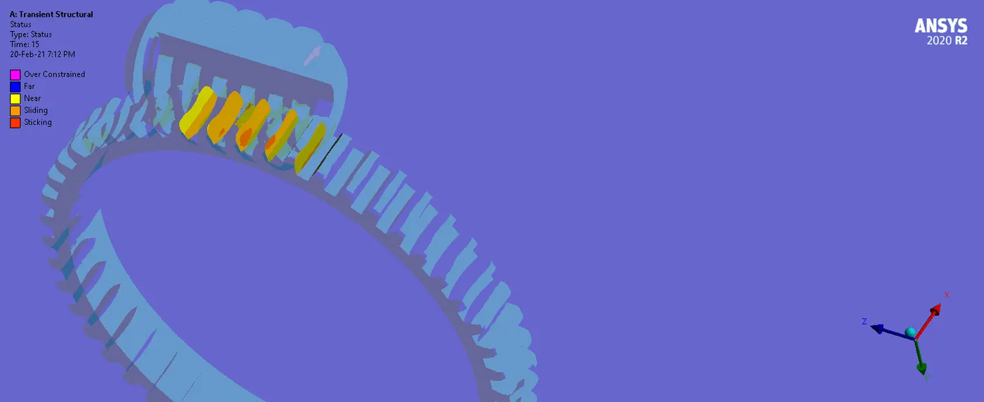
- Here we can see that while rotation of the Worm and Gear or during the transmission of motion from Worm to Gear, contact is happening.
- We can see some sliding areas on the teeth.
- We can also observe that the sliding of the teeth are not uniform, so the motion transmission will not be smooth.
_ _ _ _ _ _ _ _ _ _ _ _ _ _ _ _ _ _ _ _ _ _ _ _ _ _ _ _ _ _ _ _ _ _ _ _ _ _ _ _ _ _ _ _ _ _ _ _ _ _ _ _ _ _ _ _ _ _ _ _ _ _ _ _ __ _ _ _ _ _ _ _ _ _
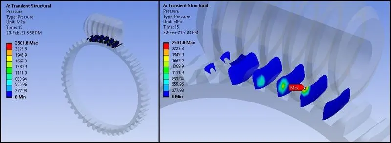
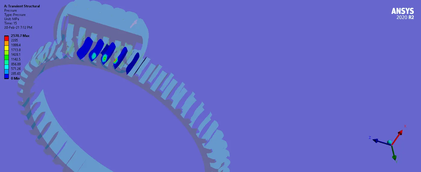
Contact Pressure Contours:
Contact Pressure Plot & Data:
- From the contours, plot and data of the pressure, we can see that the maximum pressure is occurring up to 2501.8 Mpa.
- This level of pressure is very high for the Gear motion transmission.
- Under this much high pressure, gear can break or the teeth of the gears can be worn out early.
_ _ _ _ _ _ _ _ _ _ _ _ _ _ _ _ _ _ _ _ _ _ _ _ _ _ _ _ _ _ _ _ _ _ _ _ _ _ _ _ _ _ _ _ _ _ _ _ _ _ _ _ _ _ _ _ _ _ _ _ _ _ _ _ __ _ _ _ _ _ _ _ _ _
Force & Moment Reactions:
- From the above images of Force reaction and Moment reaction, we can see that the working of the Worm and Gear is in the right way.
- Force and the Moment Reaction is in the perpendicular direction of the contact or in the global Y-Direction, which is correct for the transmission mechanism.
_________________________________________________________________________________________________________
Summary:

_________________________________________________________________________________________________________
Conclusion:
- From the results we can conclude that the Worm and Gear assembly should be made out of different material to minimize the stress and pressure and to reduce the loss of efficiency.
- Generally the Worm and Worm Gear are used with different material to reduce friction and for better transmission.
- Also due to sliding, heat may generate, which reduced the efficiency, so use of dissimilar material is necessary.
- With large number of starts of Worm and comparatively large number of teeth of the gear can improve the transmission ratio very high.
- Shape of the worm is slim compared to Gear, so higher tooth forces lead to higher deflection of the worm shaft, which can have negative consequences for the wear load capacity as well as the efficiency.
- So, for required power density, there should be advancements in bronze material, lubricants and manufacturing quality.
_________________________________________________________________________________________________________
References:
- Worm drive - Wikipedia
- A new approach for the calculation of worm shaft deflection in worm and crossed helical gear drives | Gear Solutions Magazine Your Resource to the Gear Industry
- Worms and worm gears - tec-science (tec-science.com)
- Worm gears: What are they and where are they used? (motioncontroltips.com)
_________________________________________________________________________________________________________
Animations:
Here the animations regarding Stress,Strain, Total Deformation, Pressure etc for Worm and Gear are given as below:
Stress:
Strain:
Total Deformation:
Contact Status:
Contact Pressure:
_________________________________________________________________________________________________________
Thanks & Regards,
Dharmesh Joshi