Week - 5 - Modelling Spotwelds

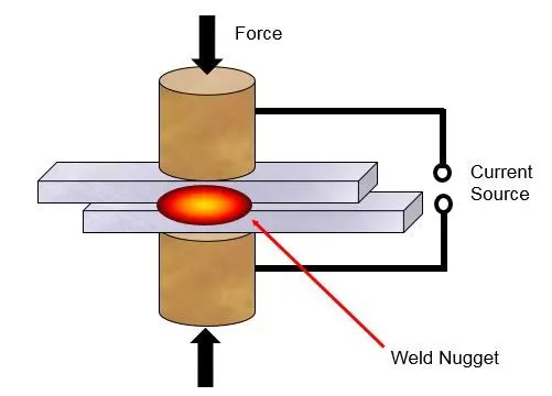
Spot welding (or resistance spot welding]) is a type of electric resistance welding used to weld various sheet metal products, through a process in which contacting metal surface points are joined by the heat obtained from resistance to electric current.
Introduction
The representation of the spotweld in finite element models has been problamatic for a number of years. The simplest representation consists of a rigid link connecting two or more sheets represented with thin shell elements. This method requires the mesh of the different sheets to be aligned, and for complex models, this poses a very difficult logistical problem. This has been addressed by using beam elements using a Tied contact to attatch the beams representing the weld to the sheet. Solid hexahedral elements can also be used in the representation of spotwelds. In this paper, the development and the methodology of applying Beam as well as hexahedral element for spotweld in connection to two different sheets will be presented, which leads to successful application of weld failure.
_______________________________________________________________________________________________________________________________________________________
Analysis
- Here we will see analysis of Spotweld with beam as well as solid (hex) element.
- There will be 7 Spotweld connections with beam as well as solid elements.
We will see two cases for Spotweld failure as given below:
- CASE_1: BEAM_SPOTWELD (Spotweld using Beam element)
- CASE_2: SOLID_SPOTWELD (Spotweld using Solid (Hexa) element)
- Unit system considered here is gm-mm-ms
_______________________________________________________________________________________________________________________________________
Geometry:
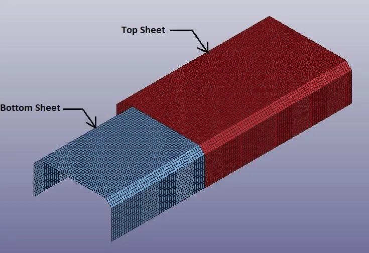
_______________________________________________________________________________________________________________________________________
Procedure:
- First of all open the L S DYNA Keyword file named as “spotweld-assignment.k” in LS-PrePost.
- After importing Crash Box, create appropriate Beam or Solid Spotweld for Top and Bottom sheets as per case.
Modeling of Beams for Spotweld:
Spotweld using Beam elements for CASE: 1
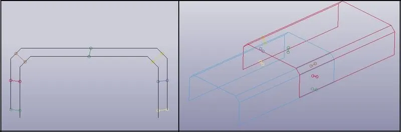
- From Element Generation tools, we can create Beam elements for Spotweld as shown in above image.
Spotweld using Solid (Hexa) elements for CASE: 2
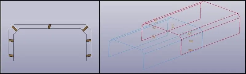
- From Element Editing tools, we can create Solid (Hexa) elements for Spotweld as shown in above image.
_ _ _ _ _ _ _ _ _ _ _ _ _ _ _ _ _ _ _ _ _ _ _ _ _ _ _ __ _ _ _ _ __ _ _ _ _ _ _ _ _ _ _ _ __ _ _ _ _ _ _ _ _ _ _ _ _ _ _ _ _ _ _ _ _ _ _
Material:
- Create material card for Top & Bottom Sheets and Spotwelds as per case.
- Here for both the cases, material for Top & Bottom Sheets as well as for Spotwelds will be same as given below:
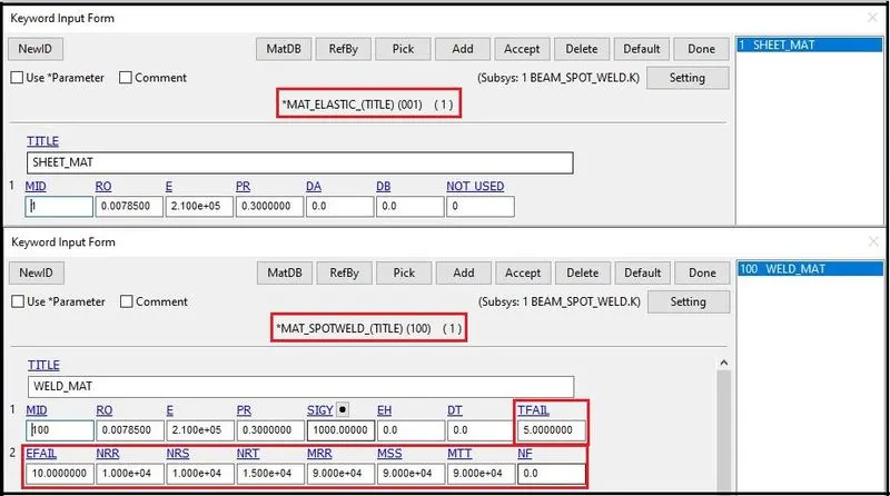
- Here in above image we can see that apart from density, young’s modulus and Poisson’s Ratio, in Spotweld material card, we have defined failure criteria also.
- TFAIL = 5 is given for failure of the Spotweld at the time of 5 ms.
- Also we have given EFAIL = 10 for failure of the Spotwelds at 10% of plastic strain.
- We have also given higher values for axial and shear forces at failure as well as moments at failure, so that we can get failure of Spotwelds either at 10 % of plastic strain or at 5 ms of time.
- When we are not sure about the forces at actual Spotweld failure, then it is good to use time dependent failure.
_ _ _ _ _ _ _ _ _ _ _ _ _ _ _ _ _ _ _ _ _ _ _ _ _ _ _ __ _ _ _ _ __ _ _ _ _ _ _ _ _ _ _ _ __ _ _ _ _ _ _ _ _ _ _ _ _ _ _ _ _ _ _ _ _ _ _
Section:
- After material card, we have to create two different Section cards as per case.
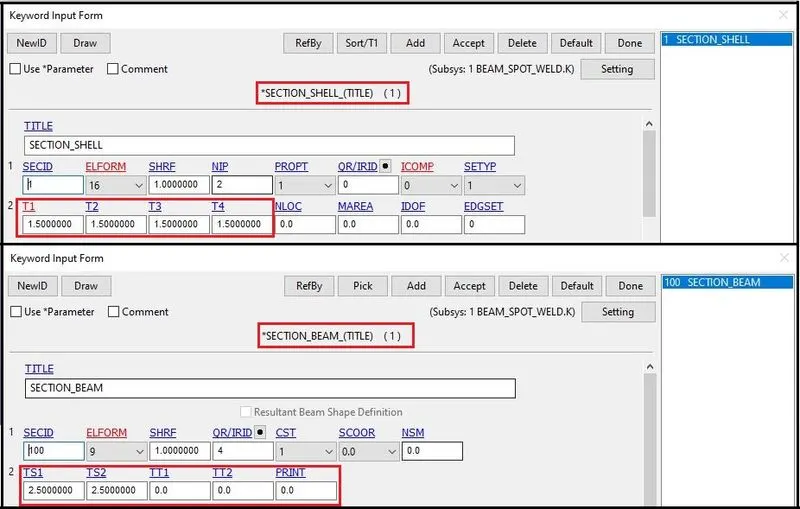
- In CASE_1, there will be section cards for shell part as well as for beam elements.
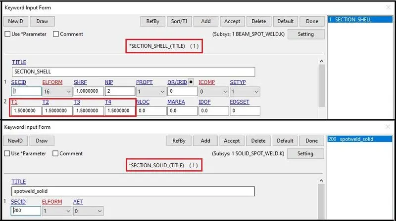
- In CASE_2, there will be section cards for shell part as well as for solid elements.
Section cards as per cases are as given below:
Section cards for CASE_1:
Section cards for CASE_2:
_ _ _ _ _ _ _ _ _ _ _ _ _ _ _ _ _ _ _ _ _ _ _ _ _ _ _ __ _ _ _ _ __ _ _ _ _ _ _ _ _ _ _ _ __ _ _ _ _ _ _ _ _ _ _ _ _ _ _ _ _ _ _ _ _ _ _
Part:
- After creation of Sections and Material, we have to assign it to the Part.
- Assignment of appropriate material as well section in part for both cases will be a given below:
Part Definition for CASE_1:
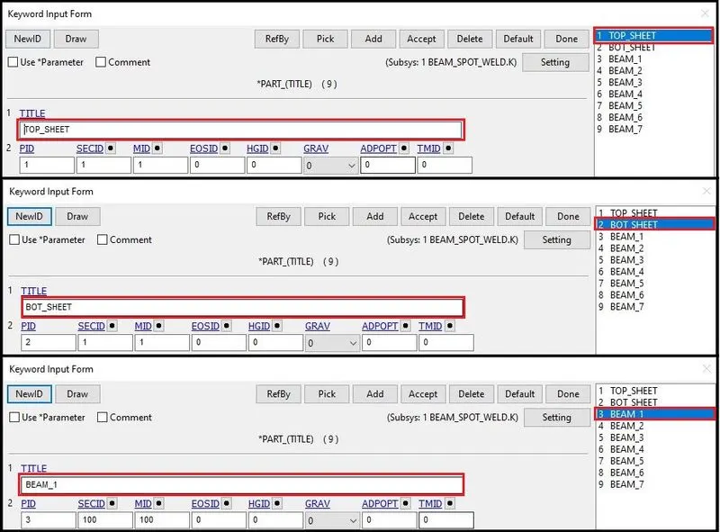
- Here we can see the Top & Bottom sheet as well 7 beam elements are assigned in part definition.
Part Definition for CASE_2:
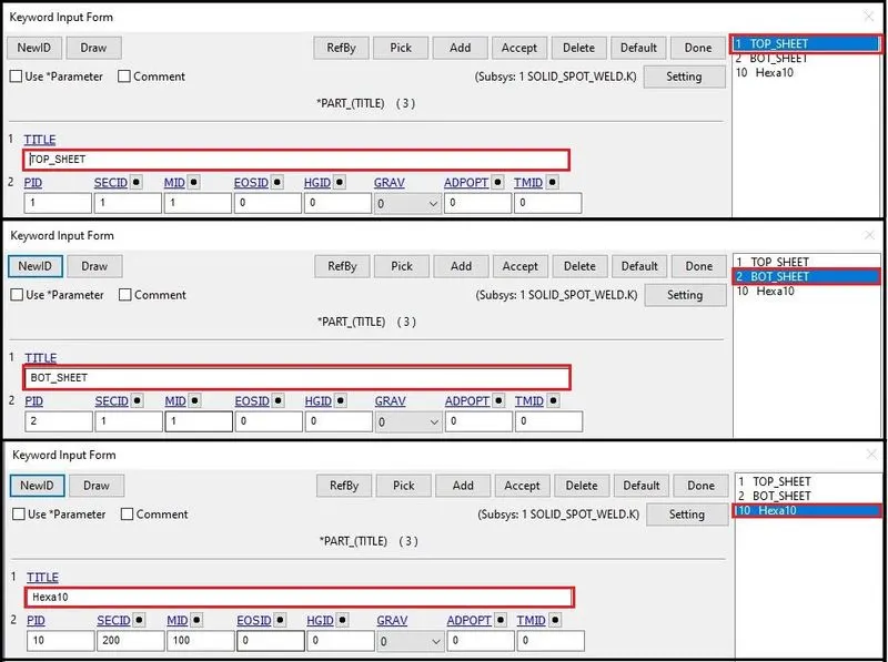
- Here we can see the Top & Bottom sheets as well as Hexa 10 for all solid elements are assigned in part definition.
_ _ _ _ _ _ _ _ _ _ _ _ _ _ _ _ _ _ _ _ _ _ _ _ _ _ _ __ _ _ _ _ __ _ _ _ _ _ _ _ _ _ _ _ __ _ _ _ _ _ _ _ _ _ _ _ _ _ _ _ _ _ _ _ _ _ _
Boundary Conditions:
- Here we will fix the Top Sheet and give the motion to the Bottom Sheet.
- Boundary conditions using single point constrained and prescribed motion have been given as described below:
Single Point Constrained:
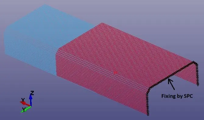
- As shown in above image, with help of Single Point Constrained, motion of the node set of Top Sheet has been locked in all direction.
Prescribed Motion:
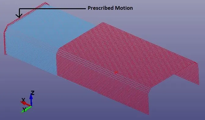
- As per above image, motion is given to the set of node of the Bottom sheet.
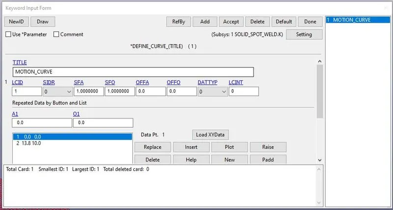
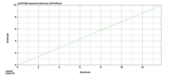
- Motion is given to the node set in the form of curve.
Curve defined for the motion of node set can be described as given below:
_ _ _ _ _ _ _ _ _ _ _ _ _ _ _ _ _ _ _ _ _ _ _ _ _ _ _ __ _ _ _ _ __ _ _ _ _ _ _ _ _ _ _ _ __ _ _ _ _ _ _ _ _ _ _ _ _ _ _ _ _ _ _ _ _ _ _
Contacts:
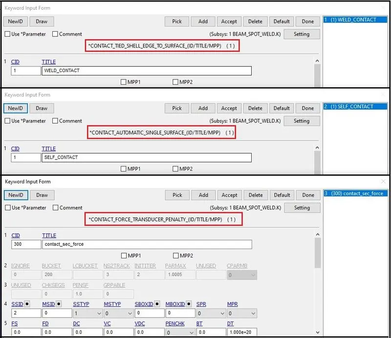
- There are total three contacts defined here.
- CONTACT_TIED SHELL_EDGE_TO_SURFACE, which gives the connection behavior of Spotweld. Here two sheets are defined as master and beam nodes are
- CONTACT_AUTOMATIC_SINGLE_SURFACE, to ensure that after Spotweld breaks, if two sheets come into contact, they should not penetrate each other. Here two sheets are defined as slave. There is no need to define any master.
- CONTACT_FORCE_TRANSDUCER_PANELTY, to get the resultant interface forces. Here all elements or set of shell elements of both sheets are defined as slave. There is no need to define any master.
Contacts are defined as given below:
_ _ _ _ _ _ _ _ _ _ _ _ _ _ _ _ _ _ _ _ _ _ _ _ _ _ _ __ _ _ _ _ __ _ _ _ _ _ _ _ _ _ _ _ __ _ _ _ _ _ _ _ _ _ _ _ _ _ _ _ _ _ _ _ _ _ _
Database:
cross_section_set:
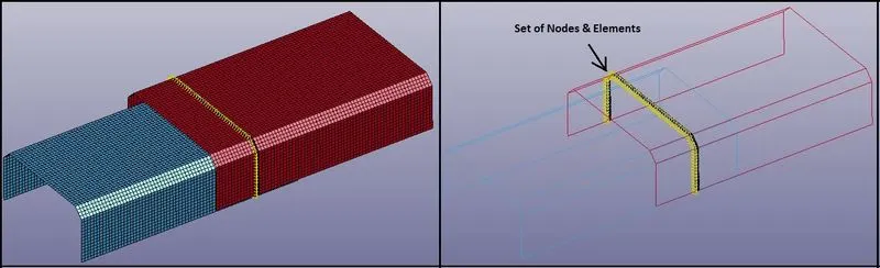
- DATABASE_CROS_SSECTION_SET keyword is used for output of the forces generated at the cross section of the Top Plate at Spotweld connection.
- Here for cross section, SET_SHELL_LIST (SSID) as well as NODE_SET_LIST (NSID) is given for the particular set off shell elements and nodes related to those elements at the Spotweld connection as shown in below image:
HISTORY NODE_set:
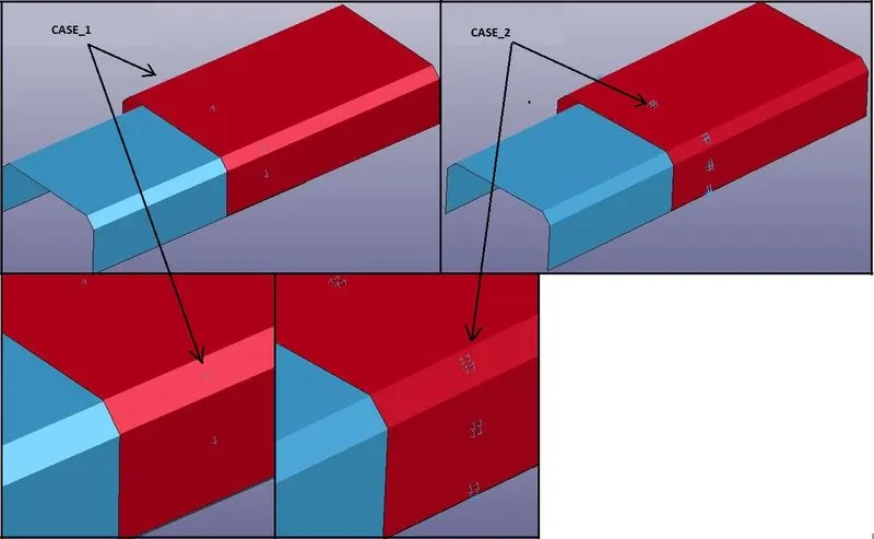
- Here DATABASE_HISTOTY_NODE_SET keyword is used to get the accelerations of the given nodes with help of NODOUT.
- Here the nodes at the Spotweld connections are defined for both of the case for history of the nodes as given below:
Binary option:
- DATABASE_BINARY_D3PLOT keyword id used for post processing data as well as animations.
- Here 1 ms time is given for output update interval.
Ascii option:
- With DATABASE_OPTION keyword, GLSTAT, RCFORC, SLEOUT, SECFORCE and SWFORC OUTPUT files has been created for global statistics, sliding interface energies, resultant interface forces, cross-sectional forces and forces at the Spotweld connections respectively.
- Also for the nodal acceleration of the nodes at Spotweld connections, output is created using NODUOT.
- All ASCII output has been created with 1 ms update interval.
_ _ _ _ _ _ _ _ _ _ _ _ _ _ _ _ _ _ _ _ _ _ _ _ _ _ _ __ _ _ _ _ __ _ _ _ _ _ _ _ _ _ _ _ __ _ _ _ _ _ _ _ _ _ _ _ _ _ _ _ _ _ _ _ _ _ _
Controls:
Energy:
- To get the output for Hourglass energy “CONTROL_ENERGY” keyword is use.
- HGEN =2 is given for computing and including the Hourglass Energy into Energy Balance.
Termination:
- Termination time to end the simulation is defined with “CONTROL_TERMINATION”.
- To see the forces on sheets and failure of Spotwelds, 10ms is given as a Termination time.
_______________________________________________________________________________________________________________________________________________________
Results & Discussion:
CASE_1- (Beam-Spotweld)
Stress:
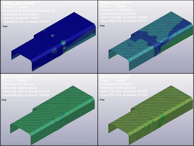
- Here we can see that maximum effective stress is generating at the time of Spotweld failure, which is 812.25 Mpa.
- Also we can observe that lateral stress in Y and Z directions are less compared to longitudinal stress in X direction because the tension is generating due to motion applied in X-direction.
- As the sheet moves, there will be tension at the Spotweld connection, and so the higher stress are generating.
- But at the failure of Spotwelds, most of the energy has been dissipated, and so after the failing of Spotweld, there will be reduction in stress.
Strain:
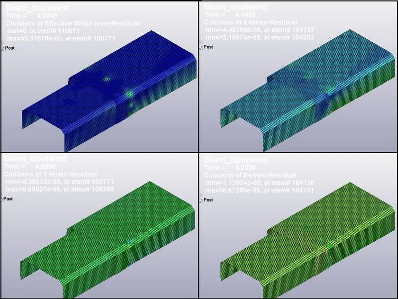
- Here we can see the permanent/ residual strain.
- Maximum residual strain is 3.51976 e-5, which is very low because the sheets are connecting only at the Spotwelds.
- But residual strain in Y and Z direction is lower than in X direction, which shows maximum strain energy dissipation in X-direction.
Global Energies:
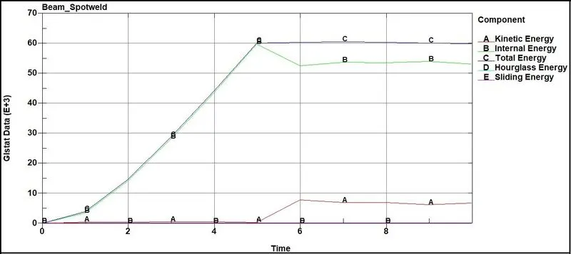
- Here we can observe decrease in kinetic energy due failure of the Spotwelds. Also there is an increase in internal energy at the time of impact at 5 ms.
- We can see some amount of sliding energy due to Spotweld connection. Shearing effect of the sheets at weld connection causes the energy dissipation. So we are getting sliding energy.
- Also Hourglass energy is within the 10% of the internal energy, which is good.
Cross section forces at Weld Connection on Top Sheet:
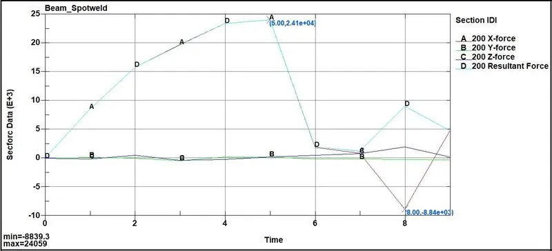
- Maximum force near Spotweld area at Top sheet cross section is 24 KN.
Nodal Acceleration (Node ID: 502731):
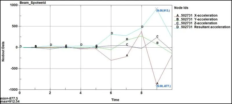
- As shown in above image, nodal acceleration of the node 502731 at Spotweld connection is 913 mm/ms2
Resultant Interface Forces:
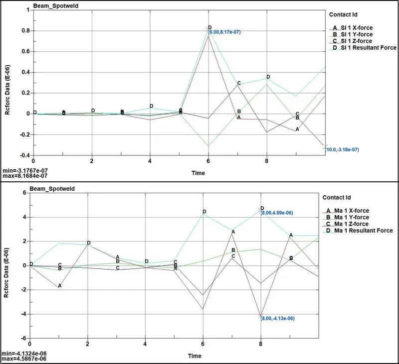
- Here we can see very low interface force on slave as well as master components. Because these are the forces measured for the interfaces and there is no any type of impact in interfaces.
- Also after the failure of the welds, there will be no connections of welds and sheets, so the resultant forces are very low.
Sliding Interface Energy:
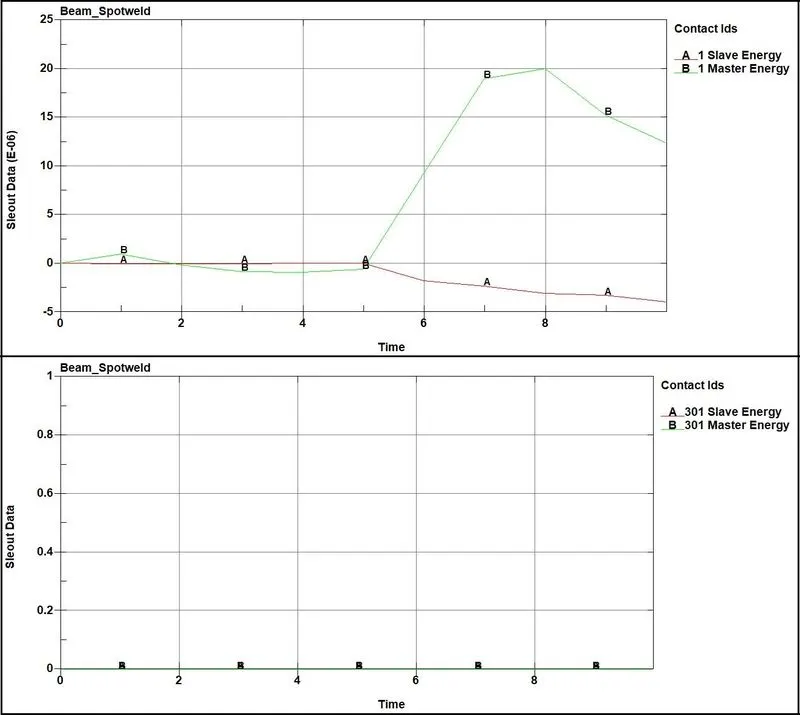
- Both normal and shear forces contribute to sliding or contact interface energy.
- Here friction coefficient is 0. So there will be no frictional energy.
- Also we can see the positive sliding interface energy, which indicates that the Spotweld connection is working well.
- There is no sliding energy in self contact; it means there was no contact between two sheets.
Spotweld Reaction forces:
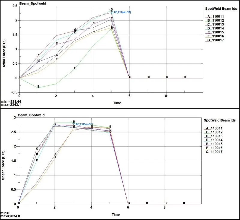
- Here we can see the maximum axial force generated is 2.34KN at 5ms.
- Also maximum shear force is 2.83 KN before the failure.
- Results shows that maximum forces are generating at the time of failure and maximum shear forces are generating before the failure. Before the weld fails, they experience the shearing effects, so shear forces are maximum before failure.
- Here we can observe that some Spotweld have negative force values, which indicates the compressive forces.
_ _ _ _ _ _ _ __ _ _ _ _ _ _ _ _ _ _ _ _ _ _ _ _ _ _ _ _ _ _ _ _ _ _ _ _ _ _ _ _ _ _ _ _ _ _ _ _ _ _ _ _ _ _ _ _ _ _ _ _ _ _ _ _ _ _ _ _ _ _ _ _ _ _
CASE_2- (Solid-Spotweld)
Stress:
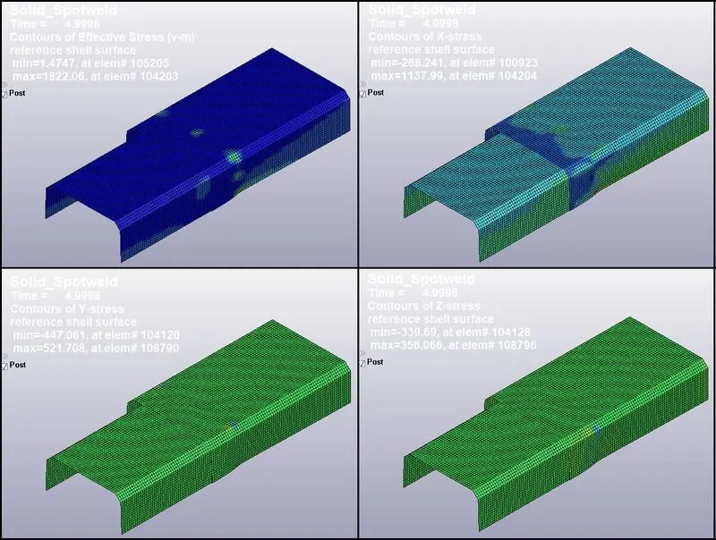
- Here we can see that maximum effective stress is generating at the time of Spotweld failure, which is 1822.06 Mpa.
- Also we can observe that lateral stress in Y and Z directions are less compared to longitudinal stress in X direction because the tension is generating due to motion applied in X-direction.
- As the sheet moves, there will be tension at the Spotweld connection, and so the higher stress are generating.
Strain:
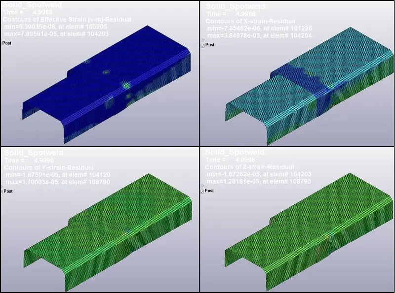
- Here we can see the permanent/ residual strain.
- Maximum residual strain is 7.89561 e-5, which is very low because the sheets are connecting only at the Spotwelds.
- But residual strain in Y and Z direction is lower than in X direction, which shows maximum strain energy dissipation in X-direction.
Global Energies:
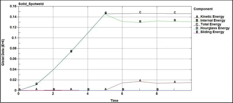
- Here we can observe decrease in kinetic energy due failure of the Spotwelds. Also there is an increase in internal energy at the time of impact at 5 ms.
- We can see some amount of sliding energy due to Spotweld connection. Shearing effect of the sheets at weld connection causes the energy dissipation. So we are getting sliding energy.
- Also Hourglass energy is within the 10% of the internal energy, which is good.
Cross section forces at Weld Connection on Top Sheet:
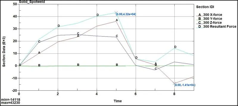
- Maximum force near Spotweld area at Top sheet cross section is 43 KN.
Nodal Acceleration (Node ID: 502731):
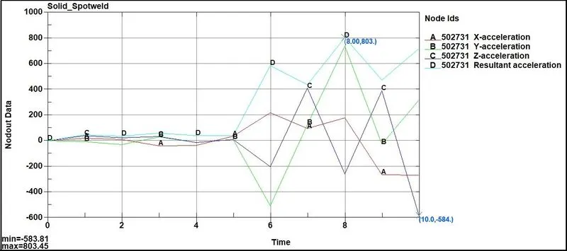
- As shown in above image, nodal acceleration of the node 502731 at Spotweld connection is 803 mm/ms2
Resultant Interface Forces:
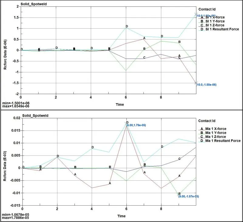
- Here we can see very low interface force on slave as well as master components. Because these are the forces measured for the interfaces and there is no any type of impact in interfaces.
- Also after the failure of the welds, there will be no connections of welds and sheets, so the resultant forces are very low.
Sliding Interface Energy:
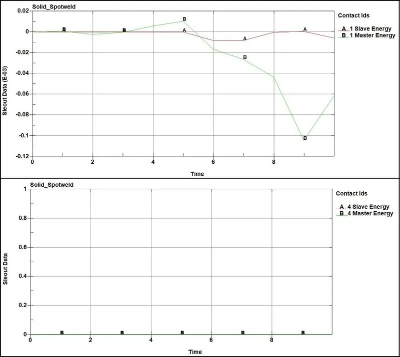
- Both normal and shear forces contribute to sliding or contact interface energy.
- Here friction coefficient is 0. So there will be no frictional energy.
- Also we can see the positive sliding interface energy, which indicates that the Spotweld connection is working well. But there is also negative energy is observed. But it is negligible.
- There is no sliding energy in self contact; it means there was no contact between two sheets.
Spotweld Reaction forces:
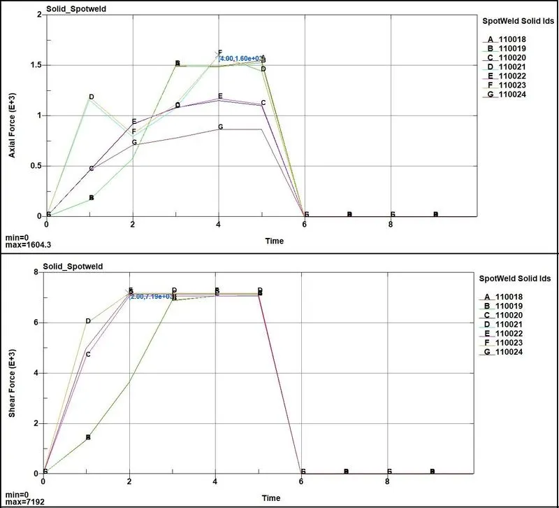
- Here we can see the maximum axial force generated is 1.6 KN at 5ms.
- Also maximum shear force is 7.19 KN before the failure.
- Results shows that maximum forces are generating at the time of failure and maximum shear forces are generating before the failure. Before the weld fails, they experience the shearing effects, so shear forces are maximum before failure.
- Here we can observe that some Spotweld have negative force values, which indicates the compressive forces.
- Here the solid Spotweld are reacting well with shearing effect. We are getting higher shear forces compared to axial forces, which is due to element type for the Spotweld used is Solid.
_ _ _ _ _ _ _ _ _ _ _ _ _ __ _ _ _ _ _ _ _ _ _ _ _ _ _ _ _ _ _ _ _ _ _ _ _ _ _ _ _ _ _ _ _ _ _ _ _ _ _ _ _ __ _ _ _ _ _ _ _ _ _ _ _ _ _
Failure of Spotweld in CASE_1 & CASE_2:
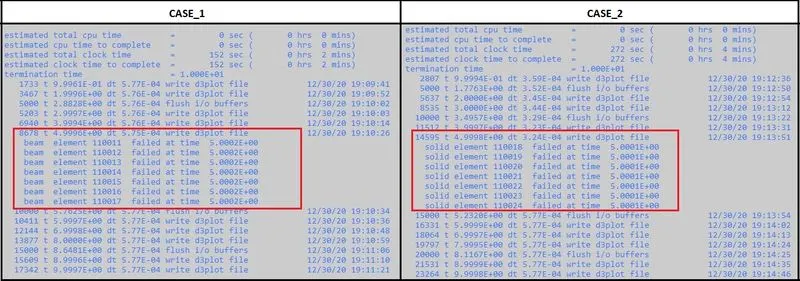
- Here we can see the Spotweld failure at 5 ms.
- In CASE_1, Beam elements are failing at 5 ms and in CASE_2, Solid elements are failing at 5 ms.
_______________________________________________________________________________________________________________________________________________________
Comparison:


- From above comparison, we can see that stresses and strains are higher in CASE_2 (Solid Spotweld).
- But the Solid Spotweld is stiffer than Beam Spotweld, so there are more cross sectional forces.
- Also there is less nodal acceleration of the node creating the Solid Spotweld compared to Beam Spotweld.
- We can observe higher axial forces in Beam Spotweld, because Beam elements can give better accuracy for axial forces.
- But Beam elements can only give accurate results for axial forces, and not able to capture shear forces.
- So we are getting higher Shear forces in Solid Spotwelds, which can give accurate results for shearing effect.
- Less Hourglass energy is generating in CASE_2, compared to CASE_1, BECAUSE OF SOLID ELEMENTS.
- Computational time can be little higher in CASE_2 due to increased number of nodes for the Spotweld connection.
_______________________________________________________________________________________________________________________________________________________
Conclusion:
- We can conclude that in order to get robust contact, solid elements are needed to represent the weld.
- Also Hex elements provide significantly improved performance over a beam element.
- We can observe the failure of e Spotwelds at the 5 ms, though we have defined percentage Plastic strain failure at 10%.
- It means the Plastic strain value does not increase more than 10 % up to 5 ms, and the Spotweld are failing due to Time dependent failure.
- When we have no accurate or standard data for the Axial & Shear forces at failure, than we can use the Time dependent failure to get the results at which the Spotwelds are failing, and for that we have to run the simulation for more longer time dependent failure or we can also use plastic strain failure also.
- From overall results, we can conclude that Solid elements are more robust and can give more accurate results and are more preferable. Though in some cases, where only axial forces are more important, or for more faster results, Beam elements can be used.
_______________________________________________________________________________________________________________________________________________________
References:
- https://en.wikipedia.org/wiki/Spot_welding#:~:text=Spot%20welding%20(or%20resistance%20spot,from%20resistance%20to%20electric%20current.
- https://app.aws.org/wj/supplement/WJ_2008_04_s96.pdf
- https://www.dynalook.com/conferences/european-conf-2001/66.pdf
- https://iopscience.iop.org/article/10.1088/1757-899X/283/1/012021/pdf
- https://www.sae.org/publications/technical-papers/content/2009-01-0354/
_______________________________________________________________________________________________________________________________________________________
Animations:
CASE_1:
Stress:

Strain:
_ _ __ _ _ _ _ _ _ _ _ __ _ _ _ _ _ _ _ _ _ _ _ _ _ _ _ _ _ _ _ _ _ _ __ _ _ _ _ _ _ _ _ _ _ _ _ _ _ _ _ _ _ _ _ _ _ _ _ _ _ _ _ _ _ _
CASE_2:
Stress:
Strain:
_______________________________________________________________________________________________________________________________________
Thanks & Regards,
Dharmesh Joshi