Week 7-Long Piston With Cam

Introduction
A Cam is a mechanical device used to transmit motion to a follower by direct contact. The driver is called the Cam and the driven member is called the follower. In a Cam-Follower pair, the Cam normally rotates while Follower may translate or oscillate. A familiar example is the crankshaft of an automobile engine, where the cams drive the push rods, where push rods are followers to open and close the valves in synchronization with the motion of pistons. Design of Cam is difficult and tough job for a design engineer as each and every competitor in industry market always looks for the better performance of mechanical system. So, a design engineer has to look for objective mechanism. Also it is important to look for better performance in actual loading conditions. With transient structural analysis we can get the idea and the behavior of the mechanism with different results such as deformation, stress ,strain etc. with respect to time.
______________________________________________________________________________________________________________________________________
Analysis
Here we will perform the Transient Structural analysis with Long Piston Cam-Follower mechanism.
We will do it with three different cases with respect to behavior of contact friction.
Cases for different contact friction behavior are describes as given below:
- CASE_1: Frictionless
- CASE_2:Friction Coefficient: 0.1
- CASE_3: Friction Coefficient: 0.2
______________________________________________________________________________________________________________________________________
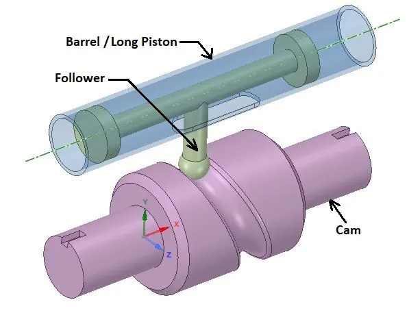
Geometry:
________________________________________________________________________________________________________________________
Material:
- Material Specifications for CASE_1:
Structural Steel
Density: 7850 Kg/m3
Young’s Modulus: 2 E+05 MPa
Poisson’s Ratio: 0.3
Tensile Yield Strength: 250 Mpa
Compressive Yield Strength: 250 MPa
Tensile Ultimate Strength: 460 MPa
______________________________________________________________________________________________________________________________________
Mesh:
Details:
- Global Element Size: Default
- Body Sizing: 3mm
- Face sizing: 1.5 mm
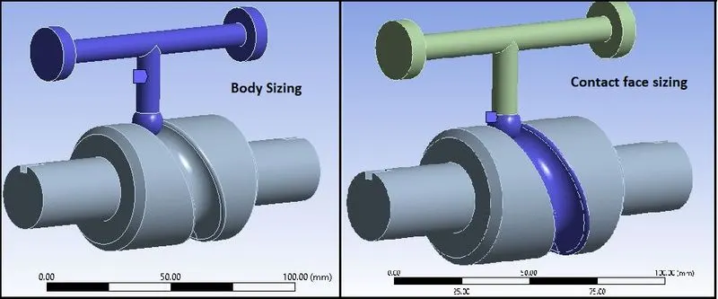
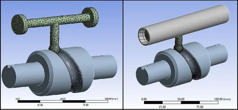
- No. of Nodes: 14620
- No. of Elements: 6977
________________________________________________________________________________________________________________________
Procedure:
- Import model in Transient Structural in Geometry section.
- Then go to Mechanical model section.
- Check or Rename the Parts of the setup as “Barrel”, “Cam” and “Follower” as shown in above geometry image.
Connections:
Contact_1:
Contact Body = Follower
Target Body = Barrel
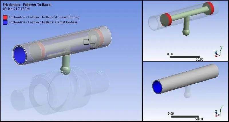
Contact_2:
Contact Body = Follower
Target Body = Cam
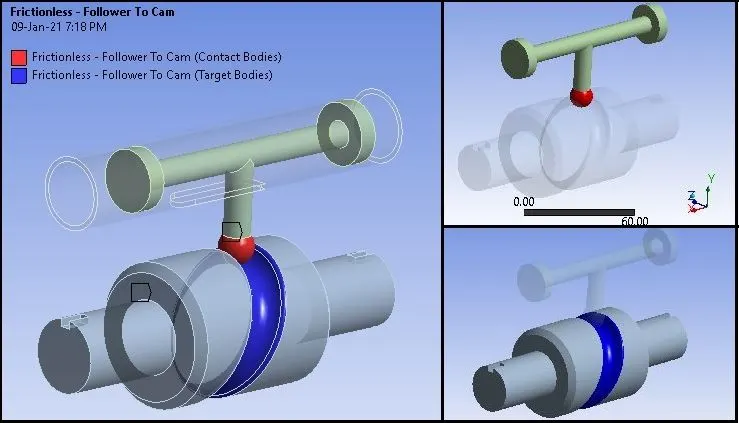
Settings for both Contacts:
For CASE_1:
- Type: Friction less
For CASE_2:
- Type: Frictional , Friction Coefficient = 0.1
For CASE_3:
- Type: Frictional , Friction Coefficient = 0.2
Joints:
Joint_1
Connection Type: Body-Ground
Type: Fixed
Body: Barrel
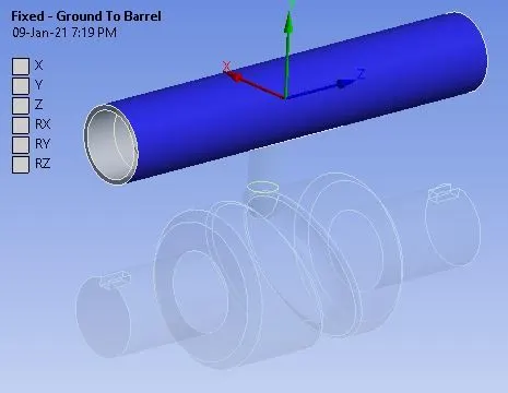
Joint_2
Connection Type: Body-Ground
Type: Revolute
Body: Cam
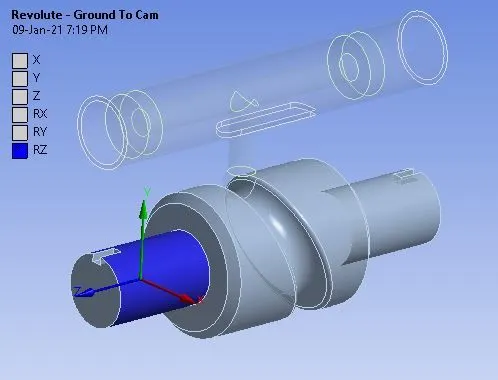
- Make sure that the Z-axis is the axis of rotation as shown in above image.
Joint_3
Connection Type: Body-Ground
Type: Translational
Body: Follower
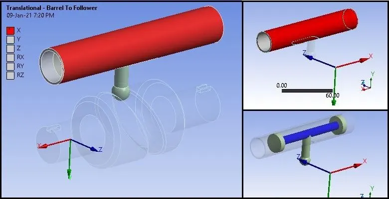
- Make sure that X-axis is the axis of translation as shown in above image.
Boundary Conditions:
- After meshing as described above, create Boundary Conditions as given below:
Analysis Settings:
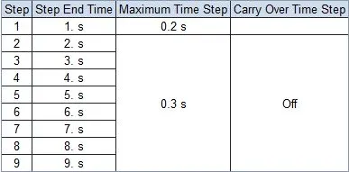
- No. of Steps: 9
For 1st Step:
- Solver Type: Program Controlled
- Weak Springs: Program Controlled
- Large Deflection: ON
- Auto Time Stepping: ON
- Defined By : Time
- Initial Time Step: 1 s
- Minimum Time Step: 5e-5 s
- Maximum Time Step: 0.2 s
- Nonlinear Controls:
- Stabilization: Constant
- Method: Energy
- Energy Dissipation Ratio: 0.1
- Update at each iteration: Yes
For 2nd to 9th t Step:
- Solver Type Program Controlled
- Weak Springs: Program Controlled
- Large Deflection: ON
- Auto Time Stepping: ON
- Defined By : Time
- Initial Time Step: 1 s
- Minimum Time Step: 5e-5 s
- Maximum Time Step: 0.3 s
- Nonlinear Controls:
- Stabilization: Constant
- Method: Energy
- Energy Dissipation Ratio: 0.1
- Update at each iteration: Yes
Joint Rotation:
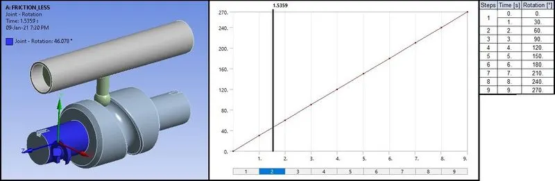
Apply Joint rotation to rotate the cam and thus the follower will follow the motion.
Solution:
- After giving proper boundary conditions, create desired solutions for output results.
- Create Solutions for :
- Equivalent Stress
- Equivalent Strain
- Directional Deformation for Follower
________________________________________________________________________________________________________________________
Results:
- Now we will see all results with comparison.
Results & Comparison of CASE_1, CASE_2 AND CASE_3:
Stress Contours:
CASE_1:
CASE_2:
CASE_3:
Stress Plots:
CASE_1:
CASE_2:
CASE_3:
Stress Data:
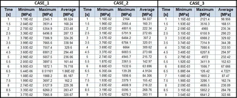
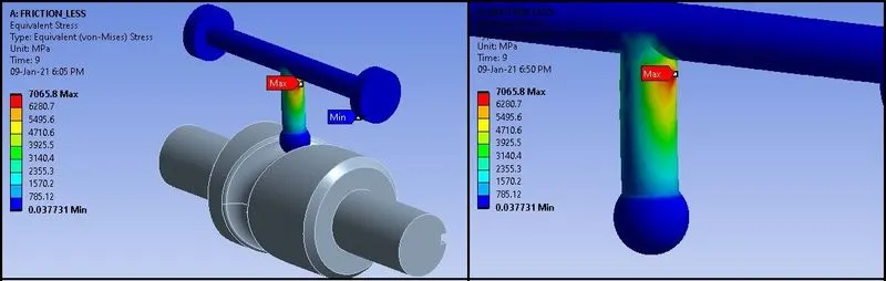
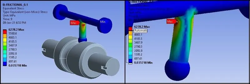
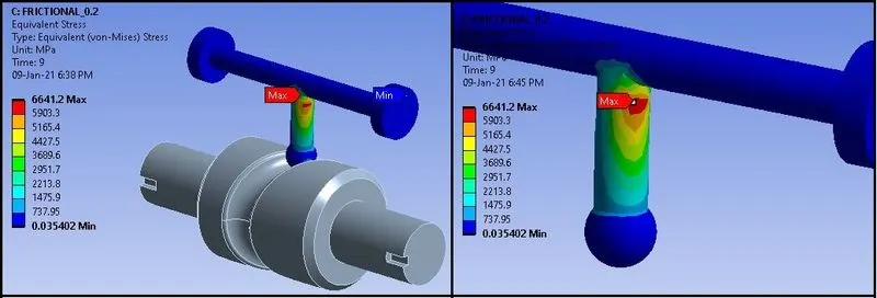
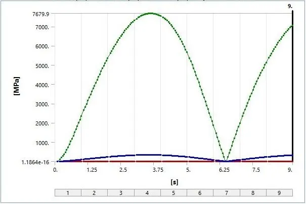
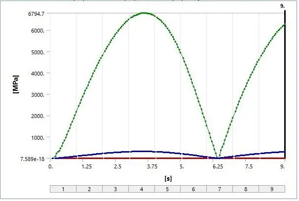
- As Per above results, we can see that stress in CASE_1 (Friction less) , is higher compared to CASE_2(friction coefficient = 0.1).
- Maximum stress occurring at the neck portion or at the right angle of the follower.
- In frictionless contact, follower can move along the cam without friction and fast. So more torque will be transferred to the follower and due to easy translation, maximum stress is generation at the right angle of follower.
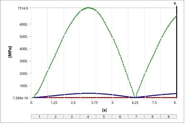
- But in CASE_3, where the friction coefficient is 0.2, maximum stress is higher compared to CASE_2. Because the increased friction, increase in stress can be observed.
- Also we can see that at the time 3.5 to 4 s, where the cam rotates from 90 to 120 degree, stress is Maximum.
- It means, maximum bend or torque is generated between 90 to 120 degree and at the 3.5 to 4 s.
_ _ _ _ _ _ _ _ _ _ _ _ _ _ _ _ _ _ _ _ _ _ _ _ _ _ _ _ _ _ _ _ _ _ _ _ _ _ __ _ _ _ _ _ _ _ _ _ _ _ _ _ _ _ __ _ _ _ _ _ _ _ _ _ _ _ _ __ _ _ _ _ _ _ _ _ _ _ _
Strain Contours:
CASE_1:
CASE_2:
CASE_3:
Strain Plots:
CASE_1:
CASE_2:
CASE_3:
Strain Data:
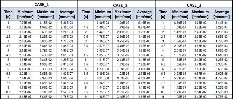
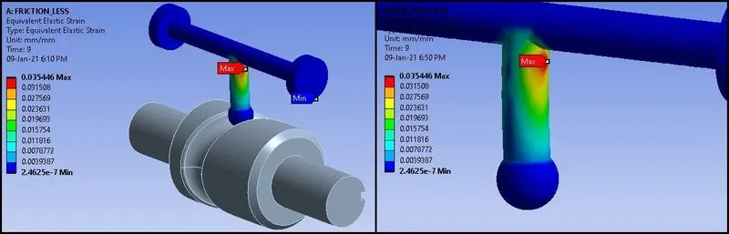
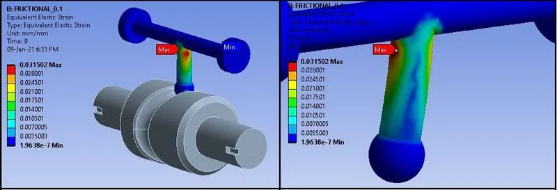
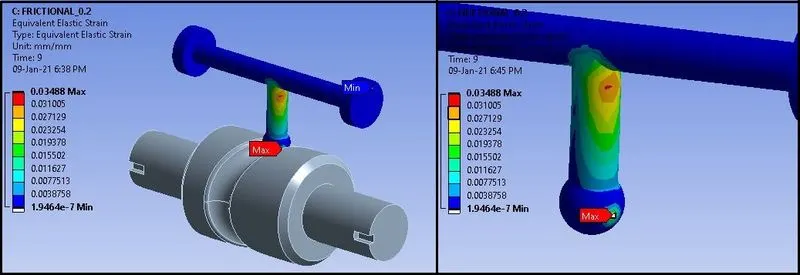
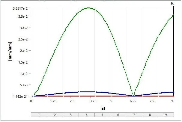
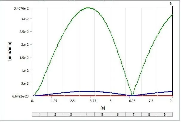
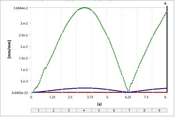
- As we know than maximum bending of follower is occurring between 90 to 120 degree of the cam rotation, we can see the maximum strain is also between the 3.5 to 4 s.
- Maximum strain is observed in CASE_3, due to higher friction compared to other cases.
_ _ _ _ _ _ _ _ _ _ _ _ _ _ _ _ _ _ _ _ _ _ _ _ _ _ _ _ _ _ _ _ _ _ _ _ _ _ __ _ _ _ _ _ _ _ _ _ _ _ _ _ _ _ __ _ _ _ _ _ _ _ _ _ _ _ _ __ _ _ _ _ _ _ _ _ _ _ _
Deformation Contours:
CASE_1:
CASE_2:
CASE_3:
Deformation Plots:
CASE_1:
CASE_2:
CASE_3:
Deformation Data:

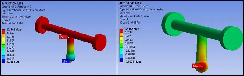
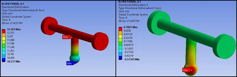
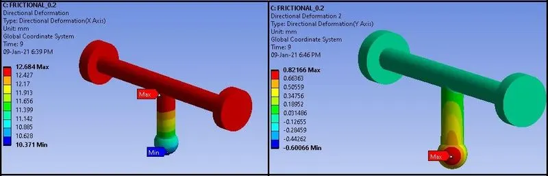
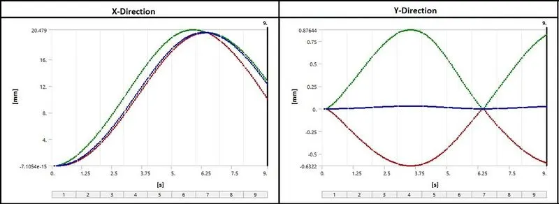
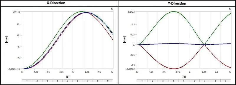
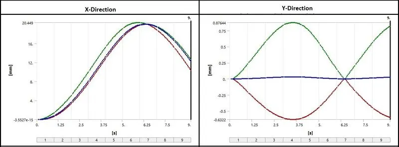
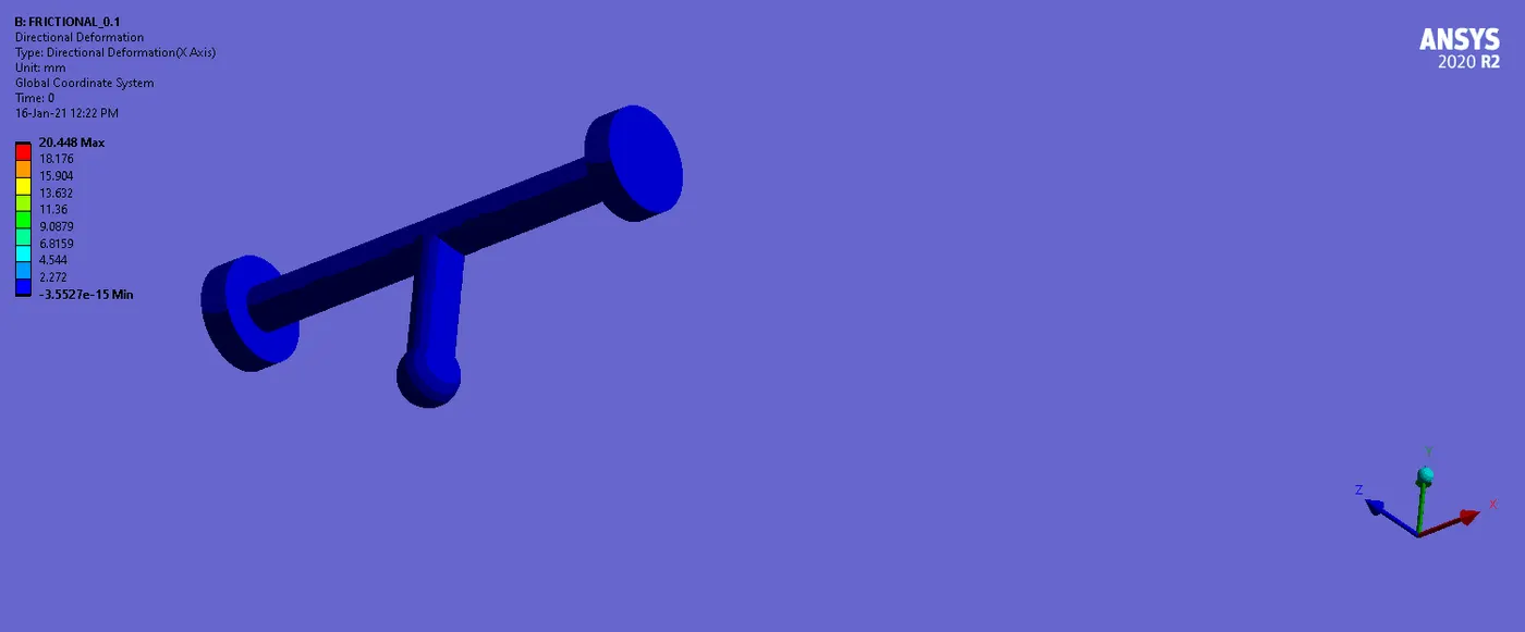
- Here we can observe the maximum deformation in X direction has very small change in all cases.
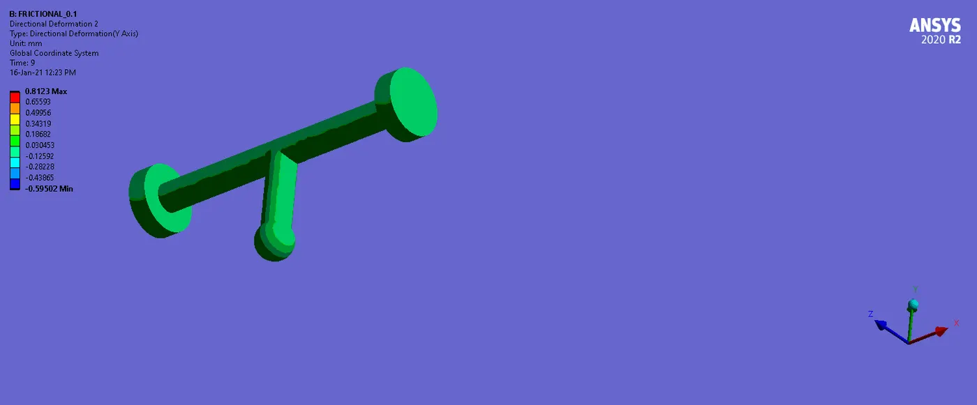
- Also due to higher pressure and repetition of acceleration as well as deceleration, there is some deformation in Y Direction also.
- This deformation is due to bending of the follower during sliding on the cam.
- Maximum deformation in Y Direction can be observed in CASE_3, which is due to higher friction.
- We can see that due to contentious acceleration and deceleration, there is maximum deformation in Y direction occurs at 3.5 s and then it decreases and also becomes maximum at 9s.
- In X direction, the follower is translating, so we can observe the maximum deformation or displacement of the follower at the 6 s, where the cam rotates about 180 degree.
______________________________________________________________________________________________________________________________________
Summary:

________________________________________________________________________________________________________________________
Conclusion:
- As we know that it is never possible to have complete frictionless contact between cam and follower.
- So, minimum friction is desired for any mechanisms.
- As per results, we can observe that as the friction increases, stress and strain values increases and deformation due to higher pressure also increases.
- When friction is higher, pressure on the tip of the follower, where it is in contact with cam, gets deformation. It can bend or twist due to the following path of the cam.
- So, minimum friction between cam & follower gives better results as in CASE_2.
- Friction coefficient plays the important role in cam & follower because of the transmission of the rotary motion to translation motion. Also the following path is also important.
- In barrel type of cam, there can be number of turns which are followed by the follower, so by minimizing the friction, we can achieve better results in terms of proper transmission and it the mechanism can work longer.
______________________________________________________________________________________________________________________________________
References:
- Cam follower - Wikipedia
- Lubrication and frictional analysis of cam–roller follower mechanisms - Shivam S Alakhramsing, Matthijn de Rooij, Dirk Jan Schipper, Mark van Drogen, 2018 (sagepub.com)
- Types of cams and followers - mech4study
- US6549341B2 - Mechanism for rotating a cam barrel of a zoom lens - Google Patents
- Characteristics of friction, wear and scuffing for cam and follower-investigating tribotechnology to improve performance and reliability for engines | Request PDF (researchgate.net)
________________________________________________________________________________________________________________________
Animations:
Animations regarding the analysis are given below.
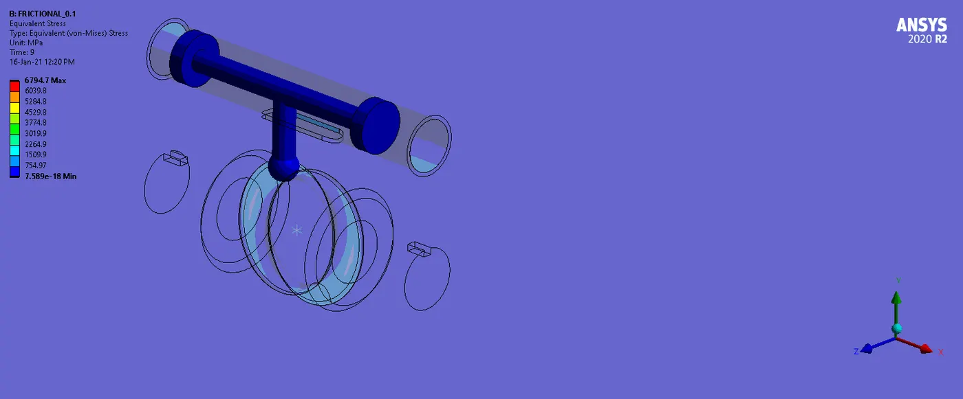
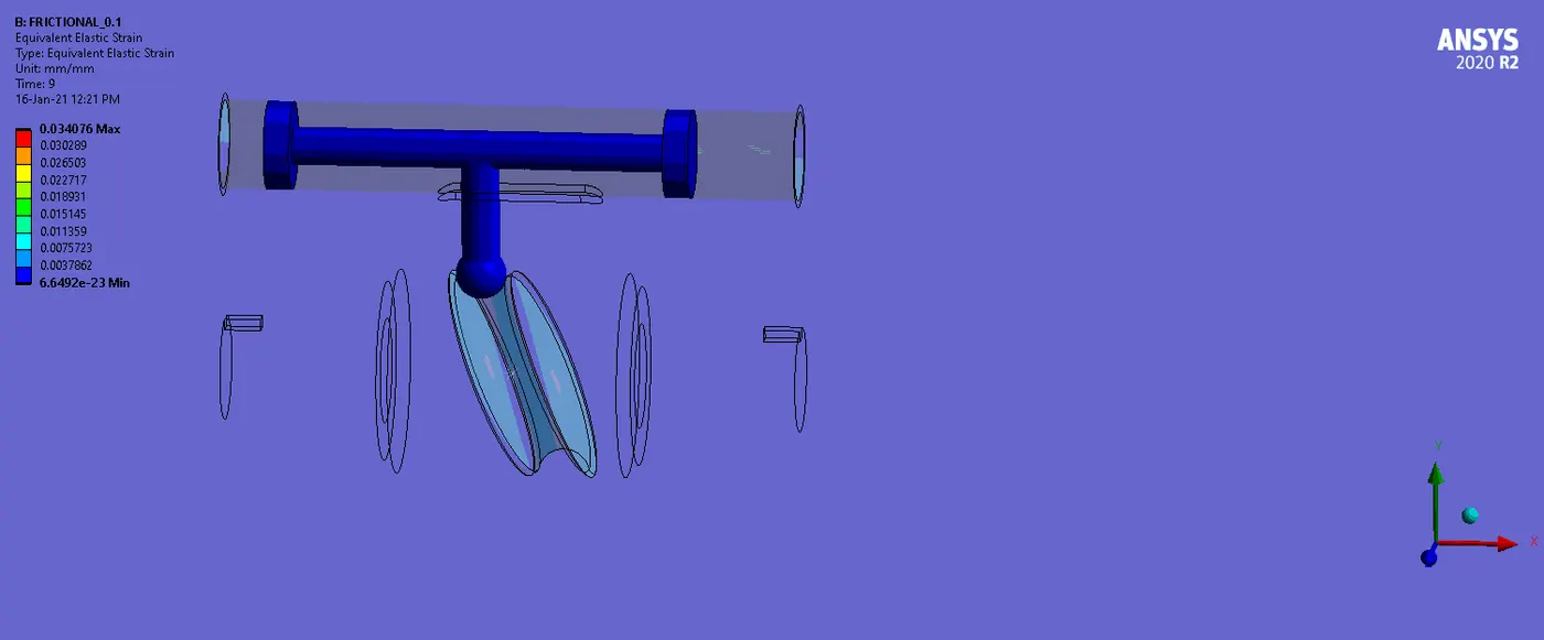
Here I have given the animations for Stress , Strain and Deformations for CASE_2 (Friction Coefficient:0.1)
Stress:
Strain:
Directional Deformation (X-Direction):
Directional Deformation (Y-Direction):
______________________________________________________________________________________________________________________________________
Thanks & Regards,
Dharmesh Joshi