Week 8 - Universal Joint

Introduction:
A universal joint (universal coupling, U-joint, Cardan joint, Spicer or Hardy Spicer joint, or Hooke's joint) is a joint or coupling connecting rigid rods whose axes are inclined to each other, and is commonly used in shafts that transmit rotary motion. It consists of a pair of hinges located close together, oriented at 90° to each other, connected by a cross shaft. The universal joint is not a constant-velocity joint.
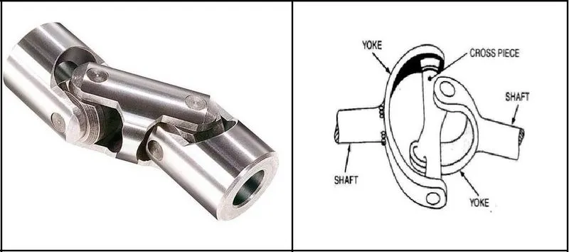
A Simple Universal joint does not transmit the motion uniformly when shafts are operating at an angle.
Because of this, two universal joints are used in a vehicle, one between the Gearbox & Propeller Shaft and other between the Propeller Shaft and the Differential Pinion Shaft.
_____________________________________________________________________________________________________________________
Analysis:
- Here we will see the Transient Analysis of a double universal joint, in which one of the shafts is attached to the spring. The spring is fixed and the rotation is transferred from one joint to another and hence the tension or compression can happen in the spring.
- So, we will see the behavior of the spring attached to the shaft or one of the joint.
- Here we will discuss the three different cases based on the material difference of the shaft attached to the spring, which have the universal joint.
Different cases as per the material difference for the shaft or spring joint are given as below:
CASE_1: Structural Steel
CASE_2: Stainless Steel
CASE_3: Titanium Alloy
_________________________________________________________________________________________________________
Geometry:
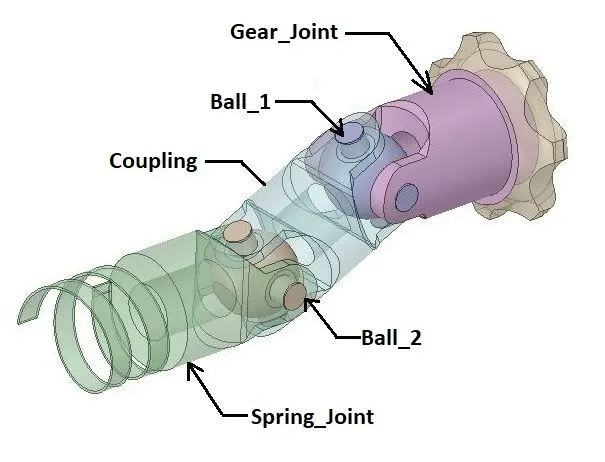
- Here we have two universal joints. One shaft is named as Gear joint, which is attached to the Gear.
- Another Shaft is named as spring joint, which is attached to the spring.
- Here we have two ball structure as a cross piece for transmission of the motion.
- Also for transmission of the motion from one joint to another, we have a coupling containing the two balls as a cross piece.
_________________________________________________________________________________________________________
Material Properties:
Material Specifications for CASE_1,2 &3 :
Structural Steel
Density: 7850 Kg/m3
Young’s Modulus: 2 E+05 MPa
Poisson’s Ratio: 0.3
Tensile Yield Strength: 250 Mpa
Compressive Yield Strength: 250 Mpa
Tensile Ultimate Strength: 460 Mpa
Stainless Steel
Density: 7750 Kg/m3
Young’s Modulus: 1.93E+05 MPa
Poisson’s Ratio: 0.31
Tensile Yield Strength: 207 Mpa
Compressive Yield Strength: 207 Mpa
Tensile Ultimate Strength: 586 Mpa
Titanium Alloy
Density: 4620 Kg/m3
Young’s Modulus: 96000 MPa
Poisson’s Ratio: 0.36
Tensile Yield Strength: 930 Mpa
Compressive Yield Strength: 930 Mpa
Tensile Ultimate Strength: 1070 Mpa
_________________________________________________________________________________________________________
Mesh:
Details:
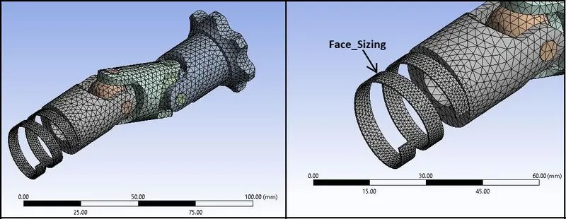
- Global Element Size: 2.5 mm
- Face Sizing: Spring =1 mm
- Use Adaptive Sizing: No
- Quality: Smoothing= Medium
- Statistics:
No.of Nodes: 43690
No.of Elements: 24521
_________________________________________________________________________________________________________
Procedure:
- Import model in Transient Structural in Geometry section.
- Then go to Mechanical model section.
- Check or Rename the Parts of the setup as “Spring_Joint”, “Gear_Joint”, “Ball_1”, “Ball_2” and “Coupling” as shown in above geometry image.
Connections:
Joints (For CASE_1, 2 & 3):
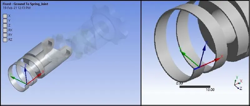
Joint_1:
Connection Type: Ground to Spring_Joint
Type: Fixed
Body: Spring_Joint
Joint_2:
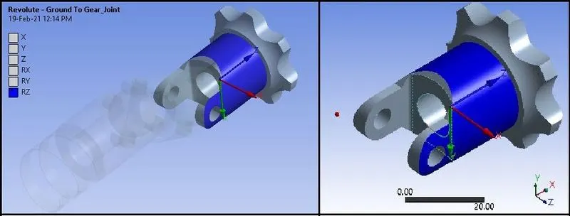
Connection Type: Ground to Gear_Joint
Type: Revolute
Body: Gear_Joint
Joint_3:
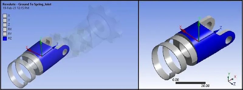
Connection Type: Ground to Spring_Joint
Type: Revolute
Body: Spring_Joint
Joint_4, 5, 6, 7:

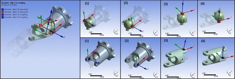
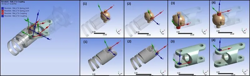
Joint_8, 9, 10, 11:

Boundary Conditions:
- After meshing as described above, create Boundary Conditions as given below:
Analysis Settings: (For CASE_1 , CASE_2 & CASE_3)
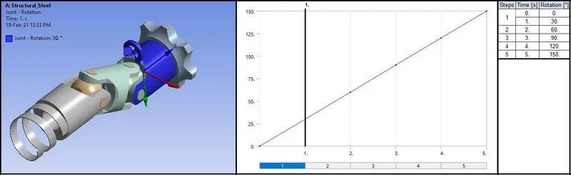
- No.of Steps: 5
- Solver Type: Program Controlled
- Weak Springs: Program Controlled
- Large Deflection: ON
- Auto Time Stepping: OFF
- Defined By : Time
- Time Step: 1 s
- Time Integration: ON
- Output Controls: Stress, Strain, Contact Data, Nodal Forces, Volume & Energy, Euler Angles, Contact Miscellaneous General Miscellaneous etc. to Yes
Joint Rotation:
- Apply Joint rotation to Gear_Joint at “Ground to Gear_Joint” joint in order to transform the rotary motion of the Gear_Joint shaft from one universal joint to another universal joint and from there to the Spring_Joint shaft and at last to the spring attached to the Spring_Joint.
Solution:
- After giving proper boundary conditions, create desired solutions for output results.
- Create Solutions for :
- Equivalent Stress
- Total Deformation
_________________________________________________________________________________________________________
Results:
- Now we will see all results and comparison for CASE_1, CASE_2 & CASE_3.
Stress Contours:
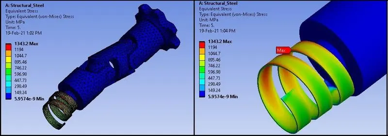
CASE_1: Structural Steel:
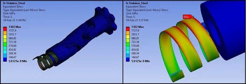
CASE_2: Stainless Steel:
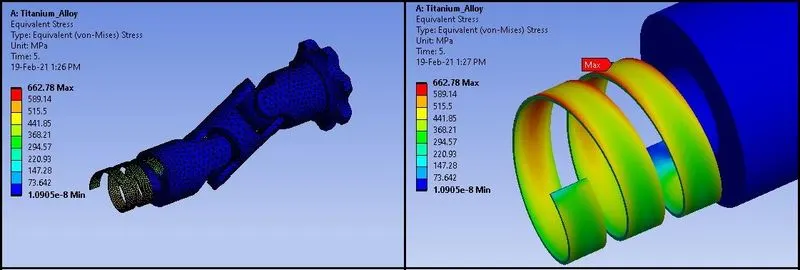
CASE_3: Titanium Alloy:
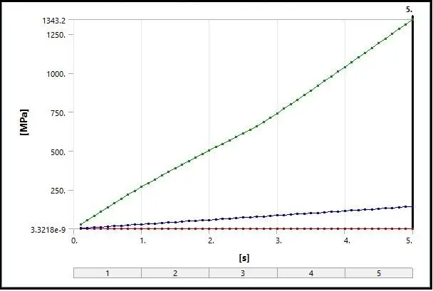
- Here we can see that the Stress in CASE_1 is highest as 1343.2 Mpa,.
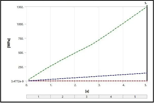
- In CASE_2, stress is little reduced as 1302 Mpa.
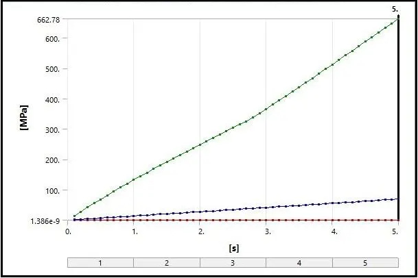
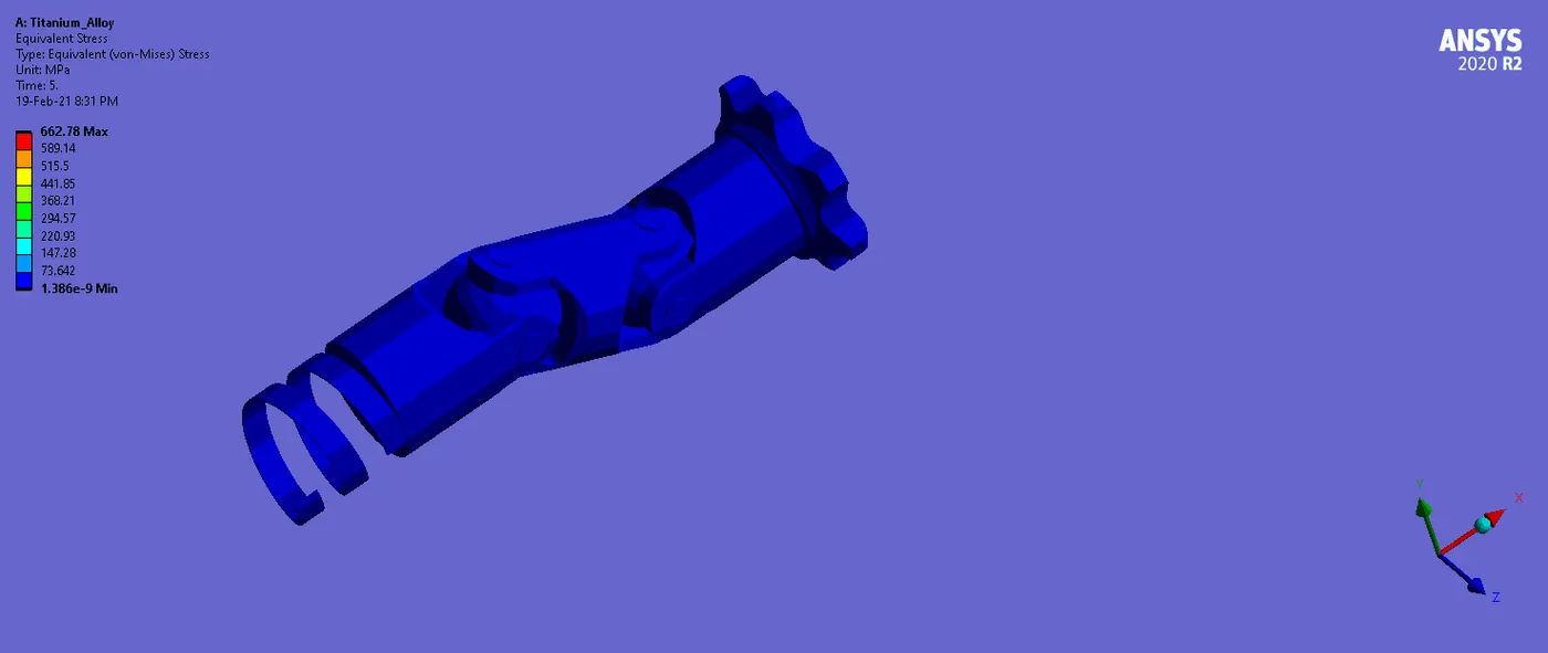
- In CASE_3, minimum stress among all the cases is 662.78 Mpa.
- Maximum stress is occuring in the Spring_Joint at the spring area.
Stress Plots:
CASE_1: Structural Steel:
CASE_2: Stainless Steel:
CASE_3: Titanium Alloy:
Stress Data:
CASE_1, 2 & 3:
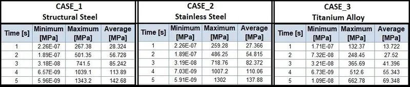
- Here from the plots and the tabular data, we can observe that the stress is increasing with the degree of rotation from 90 to 150.
- Minimum stress is at 1s or from 0 to 90 degree and maximum stress is generating at 150 degree or at 5s.
- As we know that with the rotation of the joint, the spring is getting pressed or twisted.
- So, with increase in rotation of the joint, we can see the tension in the spring and hence the value of the stress is increasing accordingly.
_ _ _ _ _ _ _ _ _ _ _ _ __ _ _ _ _ _ _ _ _ _ __ _ _ _ _ __ _ _ _ _ _ _ _ _ _ _ _ _ _ _ _ _ _ _ _ _ _ _ _ _ _ _ _ _ _ _ _ _ _ _ _ _ _ _ _ _ _ _ _ _ _
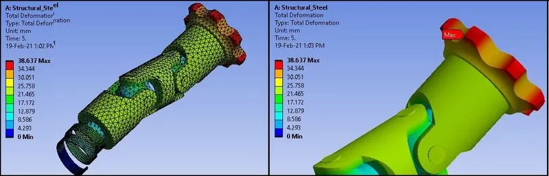
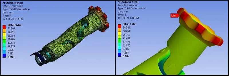
Total Deformation Contours:
CASE_1: Structural Steel:
CASE_2: Stainless Steel
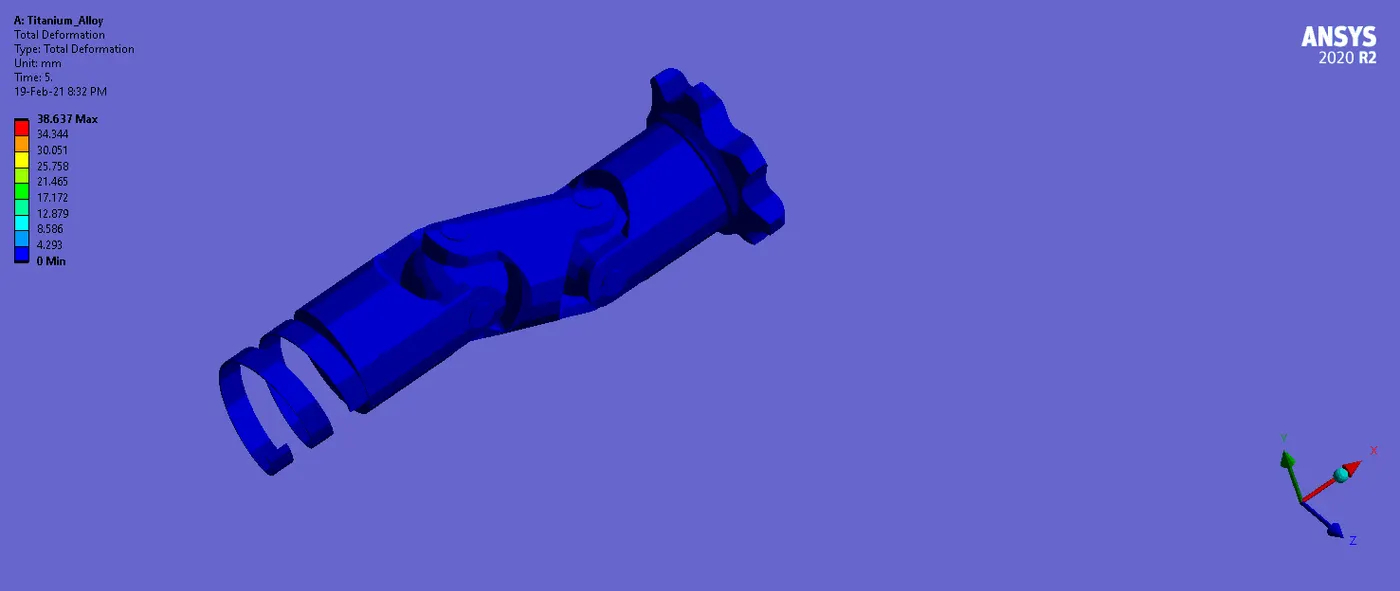
CASE_3: Titanium Alloy:
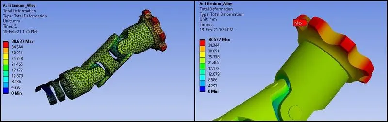
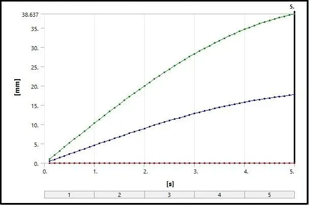
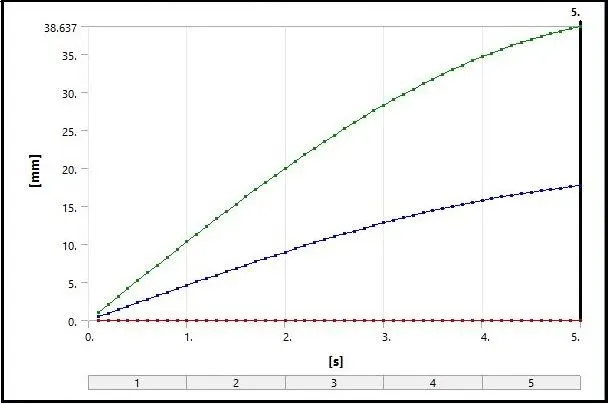
- Here the maximum total deformation can be seen by the rotation of the joint.
- Here the rotation of the joint given is the same for all the cases, so we are getting same deformation for all cases.
- Also minimum deformation can be observed at spring, because we have fixed the end of the spring.
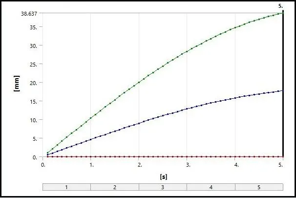
Total Deformation Plots:
CASE_1: Structural Steel:
CASE_2: Stainless Steel
CASE_3: Titanium Alloy:
Total Deformation Data:
CASE_1, 2 & 3:
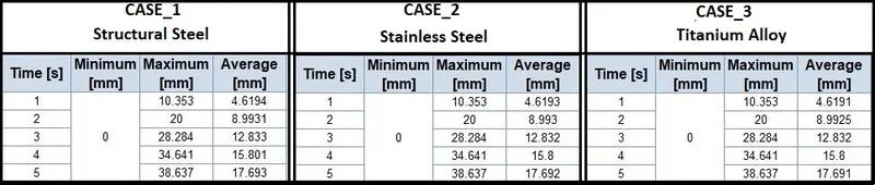
- From the plots and the tabular data, we can see that the deformation is increases as the degree of rotation increases in gradual manner.
- Here by the rotation up to 150 degree, we are getting 38.637 mm deformation for all cases.
_____________________________________________________________________________________________________________________
Summary:

_________________________________________________________________________________________________________
Conclusion:
- From the results, we can observe that the Structural Steel gives higher stress than Stainless steel and Titanium Alloy has the lowest stress.
- As we know that Titanium Alloy has the density nearly half of the Structural Steel, so it is light weight compared to Structural Steel and Stainless Steel, and so it is more flexible.
- Also the Tensile Yield Strength and Tensile Ultimate Strength of the Titanium Alloy are highest among the all material. So it has more elastic region and can regain the original shape easily and also can withstand to higher loads.
- Also in CASE_1 and CASE_2, maximum stress is exceeding the value of the yield Strength, so there is plastic deformation, but in CASE_3, maximum stress is well below the yield strength.
- Also the Ultimate strength of the Titanium Alloy is very high, so the structure is safe compared to other materials.
- So from the results and observation, we can conclude that the Titanium Alloy is very safe and effective material, which can give high performance and the mechanism of the Double Universal Joint, will be safe and can work longer.
- Thus, the alloy of the Titanium material can give good results for Universal Joint and it the best suited material.
_________________________________________________________________________________________________________
Animations:
Here the animations of Double Universal Joint of Equivalent Stress and Total Deformations for Titanium Alloy (CASE_3) , are given as below:
Equivalent Stress:
Total Deformation:
_________________________________________________________________________________________________________
Thanks & Regards,
Dharmesh Joshi