Neon Frontal Crash

Here we will perform crash analysis on neon frontal crash model and observe the different sectional forces,
Energies, forces, accelerations and displacements.
______________________________________________________________________________________________________________________________________
Procedure:
- Open given “neon_front_0000.rad” file in Hypermesh and Hypercrash.
- Check unit system: Keep the unit system as 'KN mm ms kg' in Hypercrash.
- Check components: There are 75 components.
- Check material and Properties: Material & Properties for shell as well solids are as given below:
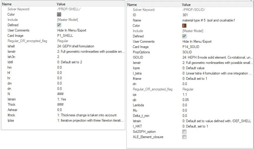
- Give ishell = 24 for QEPH shell formulation and ISOLID = 24 FOR HEPH 8-node solid element.
- Run the model checker in Hypercrash and do the changes in Hypermesh.
- If there are any errors, then make corrections as per suggested.
- Also read warnings and if there is any problematic warning, then correct it.
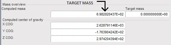
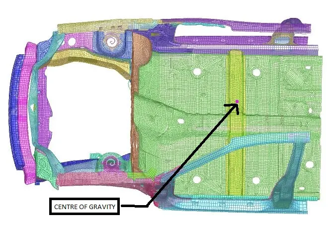
ADDED MASS: The initial weight of the model was 188kg. To reach the target weight of 700kg, extra weight was added with mass balancing on the base of the car so that the center of gravity of the vehicle was in the line with the driver and below it.
- For that, we have to delete pre-defined extra masses and add some masses on the lower part of the model as per requirement.
- We can see Target mass value and CG. Of the model as given below:
- Delete all interfaces if there are created before.
- Create an interface Type 7. Parameters of interface are as given below:
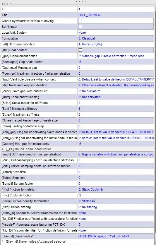
From above image, we can see the recommended parameters are as below:
Card image Type 7
Igap 3
Fscalegap 0.8
Istif 4
Idel 2
Gapmin 0.5
Stmin 1
Inacti 6
Fric 0.2
Iform 2
- Apply interface Type 7 to full body.
- In Master as well as slave, there will be the whole model.
- PENETRATIONS AND INTERSECTIONS CHECKS: Before running the model all penetrations and intersections were removed by selecting the nodes and moving manually.
- REVIEWING PARTS FOR CONNECTIONS: Connections between parts were checked and any floating spring or objects were removed.
- RIGID WALL CREATION: An infinite plane rigid wall (default) was created in front of the car in x-axis with Dsearch= 1000 and friction 0.1.
- BOUNDARY CONDITIONS: In Hypercrash create boundry condition, in which keep all the the translation abd rotational degrees free. So that we can see the full defotmation or crash with all possibilities.
- INITIAL VELOCITY: Initial velocity of 15.56mm/ms was given to all nodes of the model in x-direction.
As velocity is given in mph and unit system is in “Kg, mm, ms KN”,
So, 35 mph = 15.65 mm/ms.
We can see Rigid wall and Initial velocity as given below:
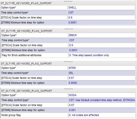
- TIME STEP CONTROL: Apply recommended parameters for controlling time step in control card in Hypercrash as given below:
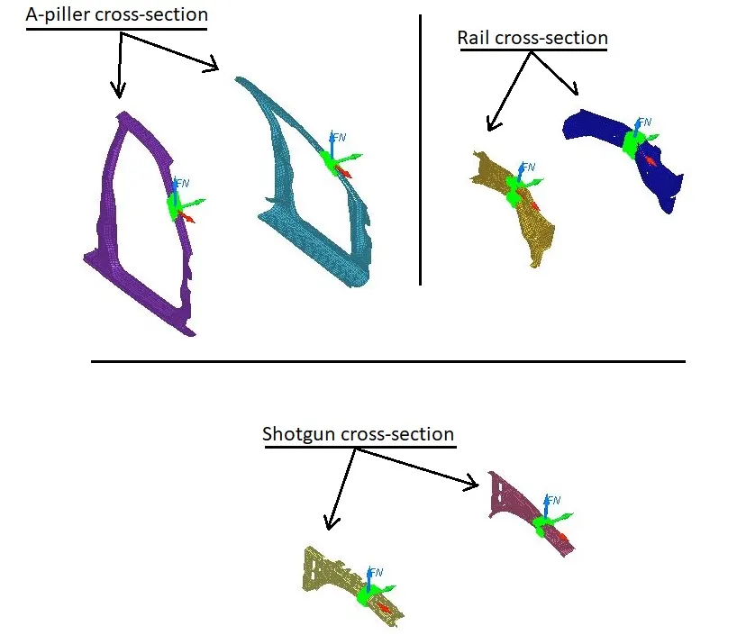
CROSS-SECTION CREATION: Create cross-sections on rails, A-piller, and Shotgun on both , left portion as well as right portion of the model on same parts as given below:
- We can create cross sections in hypermesh or hypercrash as per convenience.
- In creation of cross sections, we have to give some nodes as well as elements regarding the section.
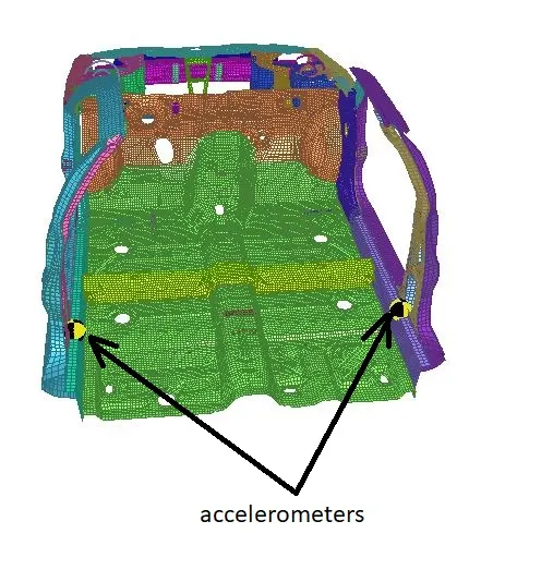
Accelerometers CREATION: Create an accelerometer on the base of the B-pillar rocker on both the side. We can see in image as below:
CREATION OF INTRUSION ON DASH WALL OF NODES 66695 & 66244:
- For intrusion of node ID 66695 , we have to create a reference frame on node ID 121739.
- For intrusion of node ID 66244 , we have to create a reference frame on node ID 122048.
- In hypermesh we can create TH file for node and for reference skew system, we can apply created frame system for intrusions.
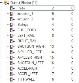
OUTPUT REQUESTS AND TH FILES: For Required output results, we have to give some requests in output block of model.
- We have to create an Output block for each and every output results which we want.
- Create output block for all sections we have created.
- Create output block for interface we have created.
- Create output block for sensors (accelerometers) we have created.
- Create output block for intrusions we have created.
We can see the output requests in output block as given below:
Analysis control card:
- Termination / Run Time = 80
- Animation output frequency = 5
- Time history Output frequency = 0.5
- After creation of all sections, accelerometers, sections, intrusions, interfaces, Rwall, Initial velocity, boundry conditions, and timestep control parameters, we have also given animation and run time and frequency for analysis.
- Now in hypermesh , in Analysis, select Radioss button and Run the Analysis.
______________________________________________________________________________________________________________________________________
Results:
- After successful run, check the elapsed time and cycles.
- Also check if the termination is normal or not.
- ELAPSED TIME =1744.69 s
0:29:04
- TOTAL NUMBER OF CYCLES : 80001
ENERGY ERROR & MASS ERROR CHECK:
See the image given below:
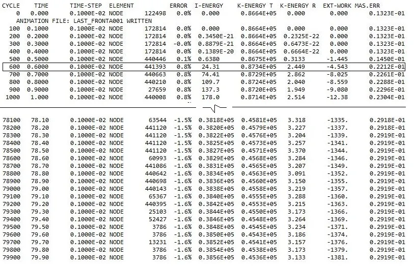
- As we can see in above image, at time 0.6 ms, mass is added, and the same time, increase in kinetic energy we can see as per Newton’s law.
- There is also high internal energy, which is due to impact of frontal portion to the rigid wall.
- Maximum Energy Error is -1.6%, which is below the limiting value.
- Also Mass addition percentage is also 2.9%, which is below 3%. This is because of controlling the time step.
SECTIONAL FORCES IN THE RAILS AT LOCATION OF INDICATED NODE 174247 (LEFT & RIGHT):
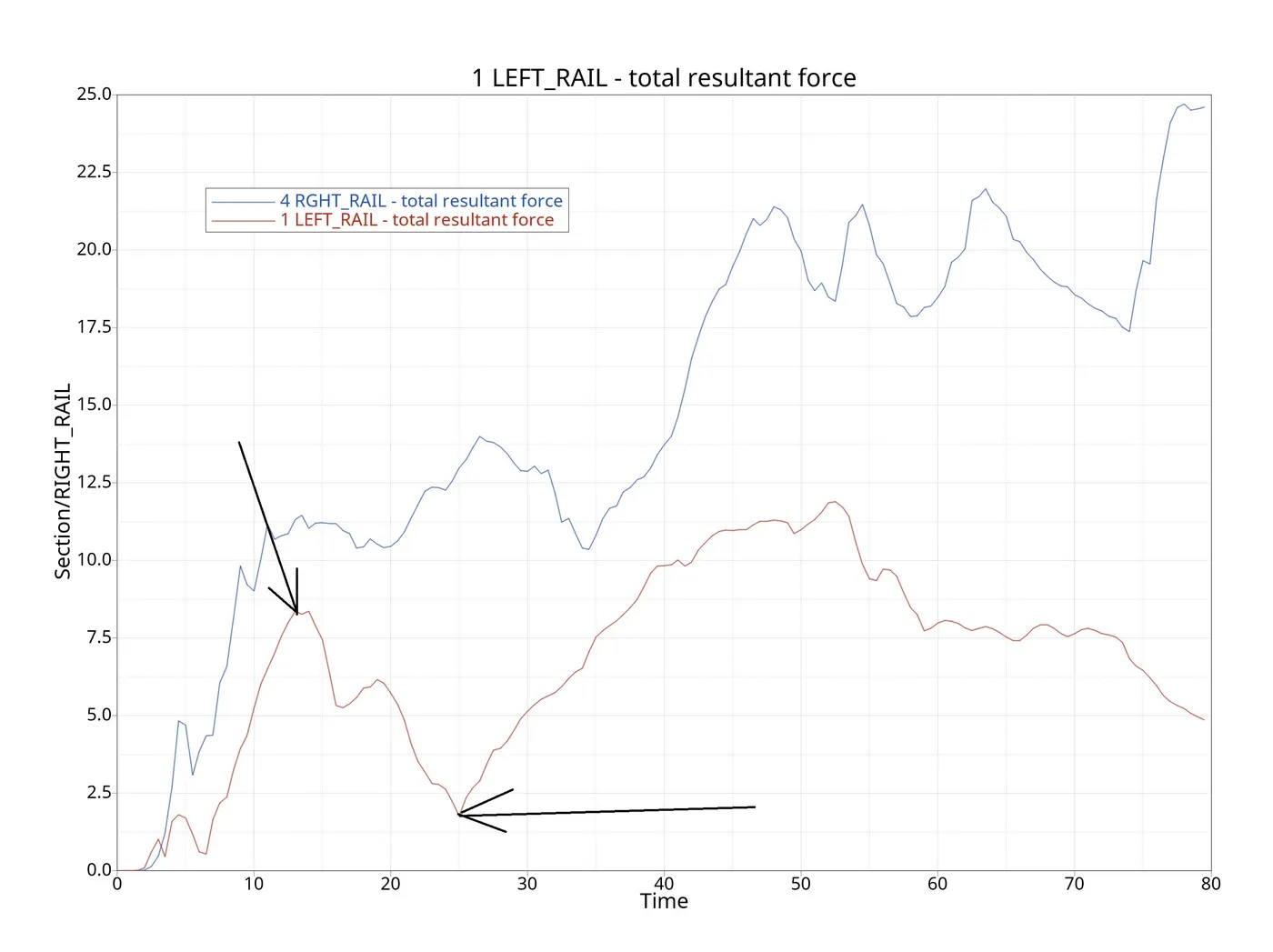
- As we can see in above image the difference resultant forces at indicated node, in left and right portion.
- We can see max force on the rail components is 21KN around 15 milliseconds. After this, there is a large deformation around node 174247 in left portion.
- During the deformation phase from 15 to 30 milliseconds, the sectional force dropped gradually. After the collision, the least force across the section was observed at 25 milliseconds.
- Maximum force observed in right rail is 24.6 KN at 79.5ms.
SECTIONAL FORCES IN THE SHOTGUN (LEFT & RIGHT):
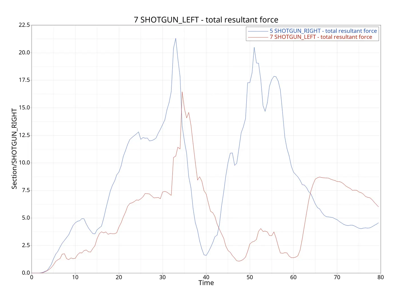
- The above graph shows the sectional force received by a shotgun. The maximum force for the right section, during the collision, is 21.3 KN at 33 ms. We can see that initially right shotgun experiences high force then as time passes force on right shotgun decreases and force on left shotgun starts increasing.
SECTIONAL FORCES IN A – PILLER (LEFT & RIGHT):
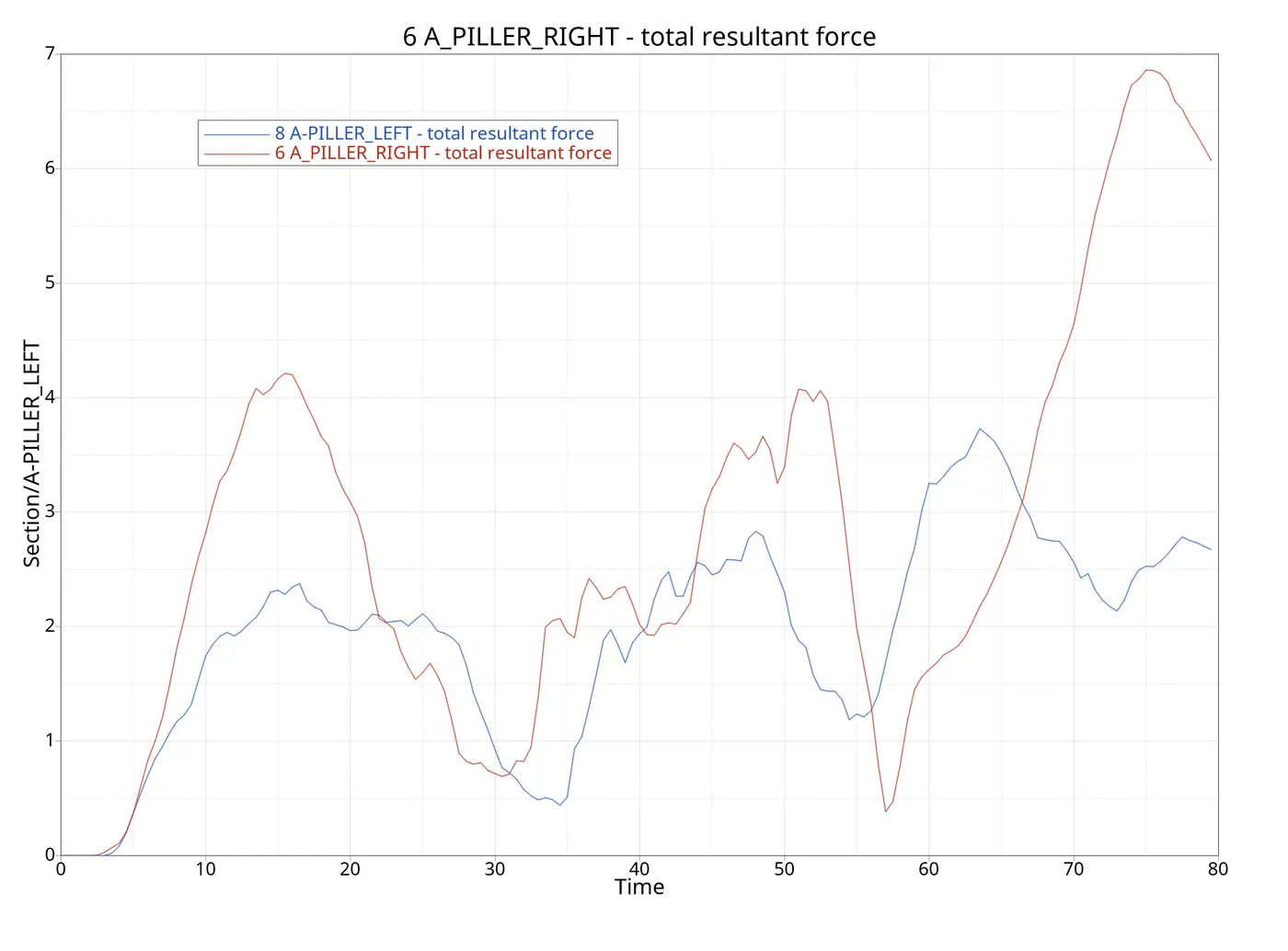
- In below plot we can see that right pillar experiences more force than left pillar but the forces are very less when compared with the shotgun and rail forces.
- The result of less force due to crash first bumper hits the object where there is high force and then gradually decreases as the energy dissipates.
ACCELERATION IN ACCELEROMETERS (LEFT & RIGHT):
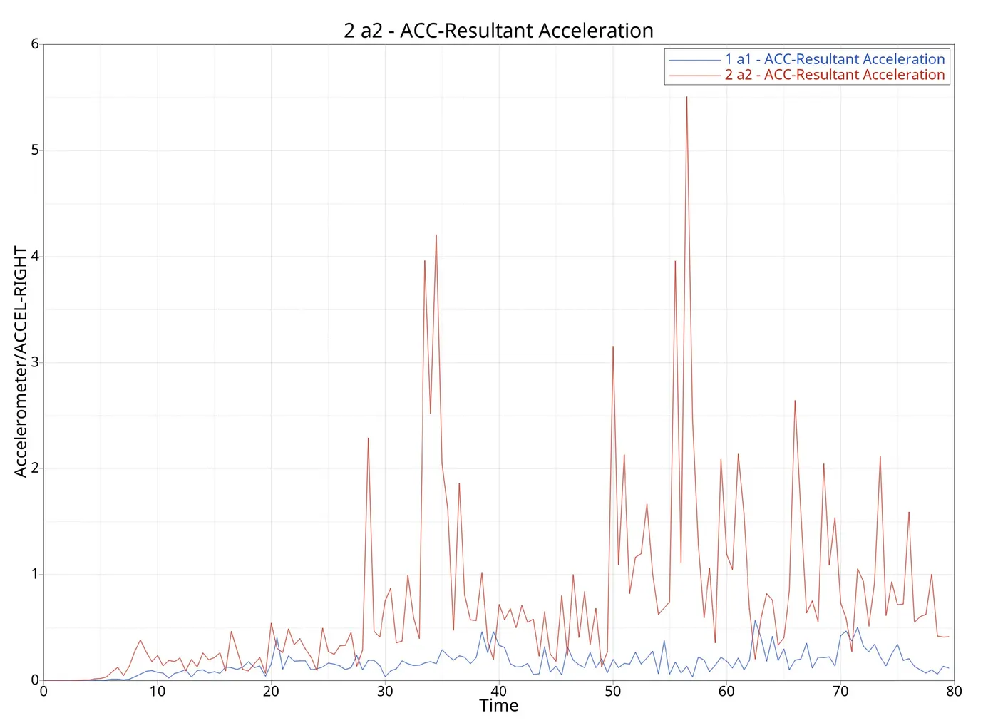
- Two accelerometers were placed at the bottom of B-pillar (B-pillar rocker) to measure the accelerations.
- We can see the acceleration of both left and right accelerometers.
INTRUSIONS ON DASH WALL ( 66695 & 66244):
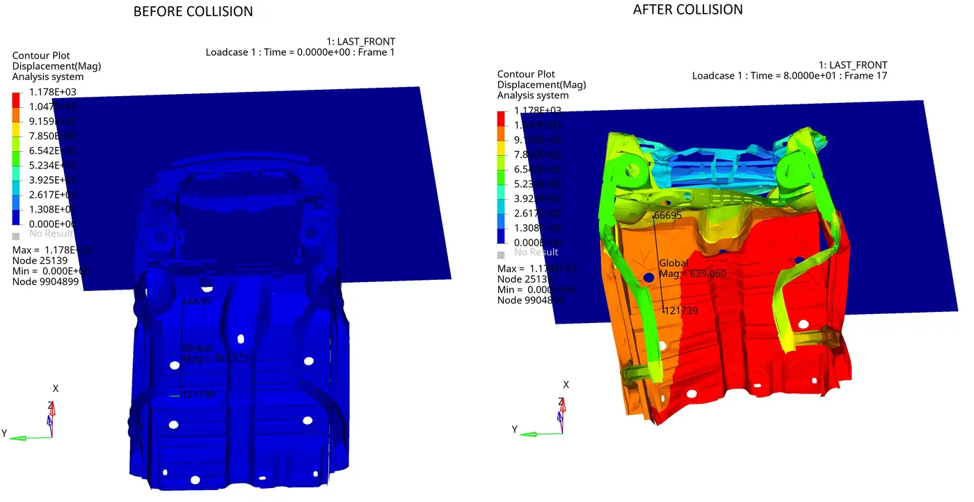
- INTRUSION 1 = Intrusion of node 66695 with respect to node 121739
Initial distance was 767.575 mm and then it decreased after collision to 639.060 mm.
So intrusion of 66695 = 767.575 – 639.060 = 128.515 mm
- INTRUSION 2 = Intrusion of node 66244 with respect to node 122048
Initial distance was 781.808 mm and then it decreased after collision to 632.505 mm.
So intrusion of 66695 = 781.808 – 632.505 = 149.303 mm
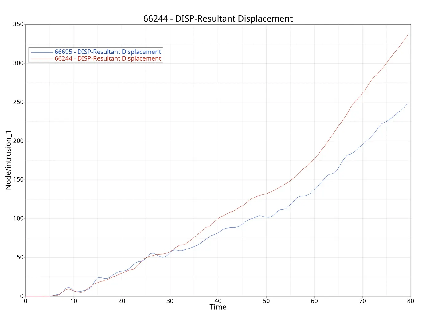
- Intrusion 1 is less then Intrusion 2.
- Lower the Intrusion, higher will be the safety.
We can see the intrusions as given below:
Intrusion 1:
Intrusion 2:
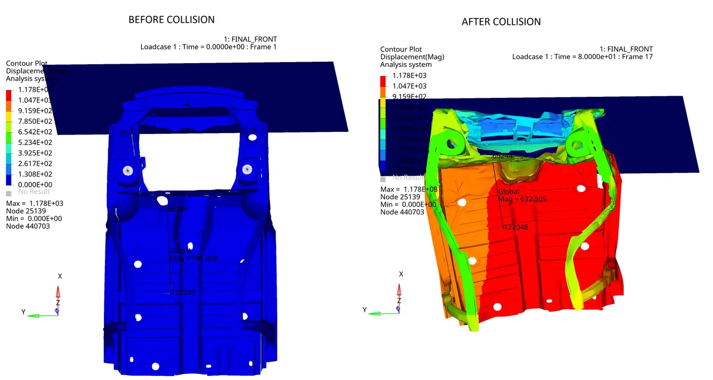
Displacement due to intrusion:
GLOBAL ENERGY GRAPHS:
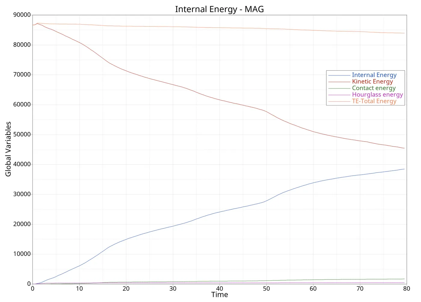
- We know that K.E. coverts to I.E. during the crash as elements get deformed and absorbs the energy. If more energy is absorbed then fewer elements will get deformed.
- Total energy remains same. Here we can see slight decrease in total energy, which is because of energy loss. There is some extra work done happening, which is not considered in total energy.
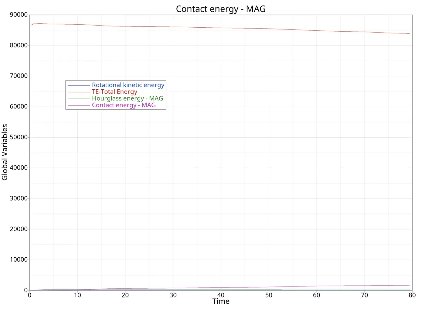
- In above image, we can see the graph of total energy, hourglass energy and contact energy.
- As per recommendation, hourglass energy + contact energy is less the 15% of total energy.
- Low hourglass energy is due to physical stabilization of hourglass deformation by QEPH shell formulation.
STRESS & STRAIN RESULTS:
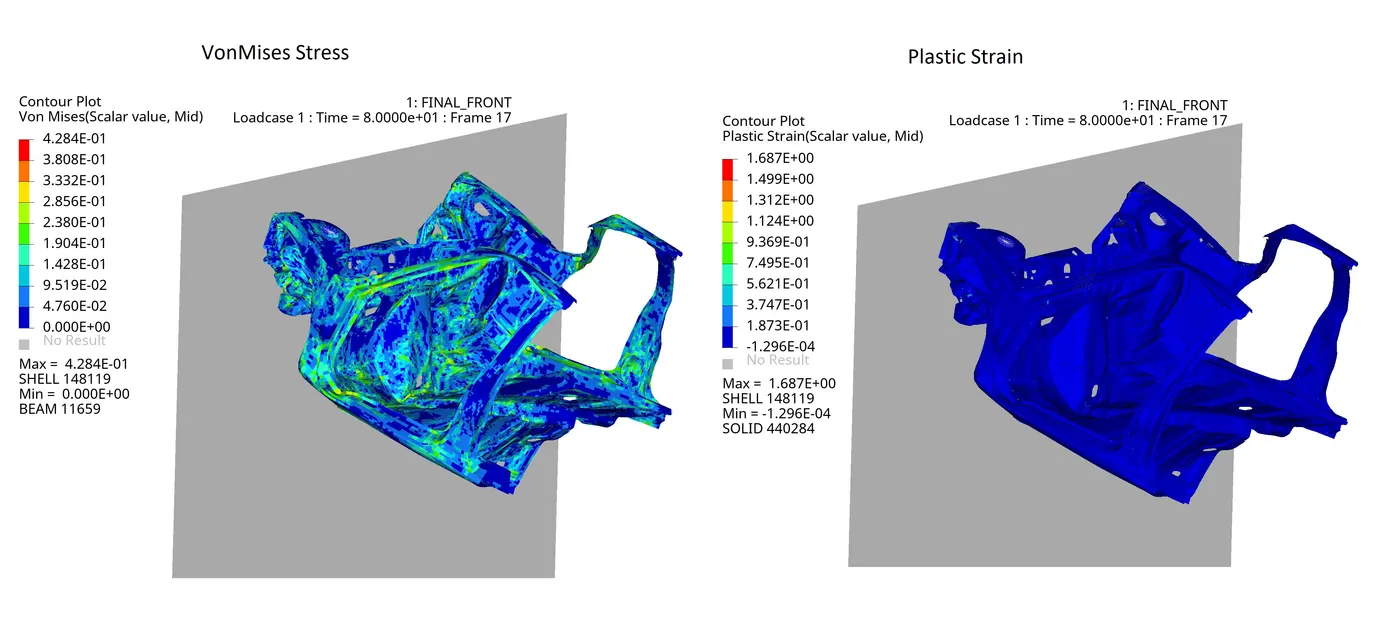
- We can see the results of VonMises stress and plastic strain as given below:
________________________________________________________________________________________________________________________
Summary :
Max force for a cross-section of A-pillar (right) = 6.85 KN
Max force for a cross-section of A-pillar (left) = 3.72 KN
Max force for shotgun cross-section (right) = 21.3 KN
Max force for shotgun cross-section (left) = 16.5 KN
Max force for shotgun rail (right) = 24.5 KN
Max force for shotgun rail (left) = 11.9KN
Displacement of 66695 node =128.515 mm
Displacement of 66244 node =149.303 mm
Maximum VonMises Stress = 428.4 Mpa
Maximum Plastic Strain = 1.687
______________________________________________________________________________________________________________________________________
Conclusion:
- G. of a car is very important, so additional mass should be added in a realistic way.
- More forces are acting on the right side of the car, because C.G. lies in the right portion of the car below the driver.
- Maximum forces are transferred to rails and shotgun components compare to A-pillar, which shows that these components are more strengthen than A-pillar.
- From observation, we can see the addition of mass is done while controlling the time step.
- Also during the mass addition, we can see increase in K.E. also.
- QEPH for shell and HEPH for solid help in decreasing the hourglass energy with friction penalty formulation with stiffness.
- Normal termination, less energy error up to -1.6% and DM/M les then 3% are good for accurate analysis.
- We can observe no energy error in starting of run, due to solved zero intersections and penetrations on model, so there is no energy need to depanetrate them.
- Due to first impact of bumper to the wall, more of the energy can be absorbed by it and the less damage to the rest of the body.
- Also plastic strain is also below 30% of total strain.
______________________________________________________________________________________________________________________________________
Regards,
Dharmesh Joshi