Week 3 Verification of Weld Joints

Introduction:
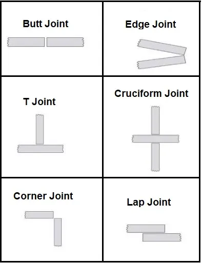
A welding joint is a point or edge where two or more pieces of metal or plastic are joined together. They are formed by welding two or more workpieces (metal or plastic) according to a particular geometry. There are five types of joints referred to by the American Welding Society: butt, corner, edge, lap, and tee. These configurations may have various configurations at the joint where actual welding can occur.
The complete Welded Joint may be referred as a Weldment.
Common Joint Configuration:
- Butt Joint
- T Joint
- Corner Joint
- Edge Joint
- Cruciform Joint
- Lap Joint
Images for the Joint configuration are as given below:
Types of Welding Joints:
Based on Configuration:
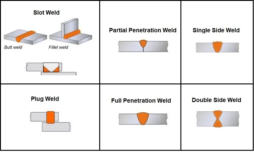
- Slot Weld
- Plug Weld
Based on Penetration:
- Full Penetration Weld
- Partial Penetration Weld
Based on Accessibility:
- Single Side Weld
- Double Side Weld
Images for the Weld Joints are as given below:
______________________________________________________________________________________________________________________________________
Analysis:
Structural verification of Weld Joints Model will be categorized in 3 different cases with some changes of Material for Weldments, Plates and Ribs as given below:
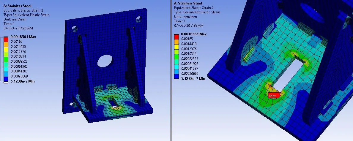
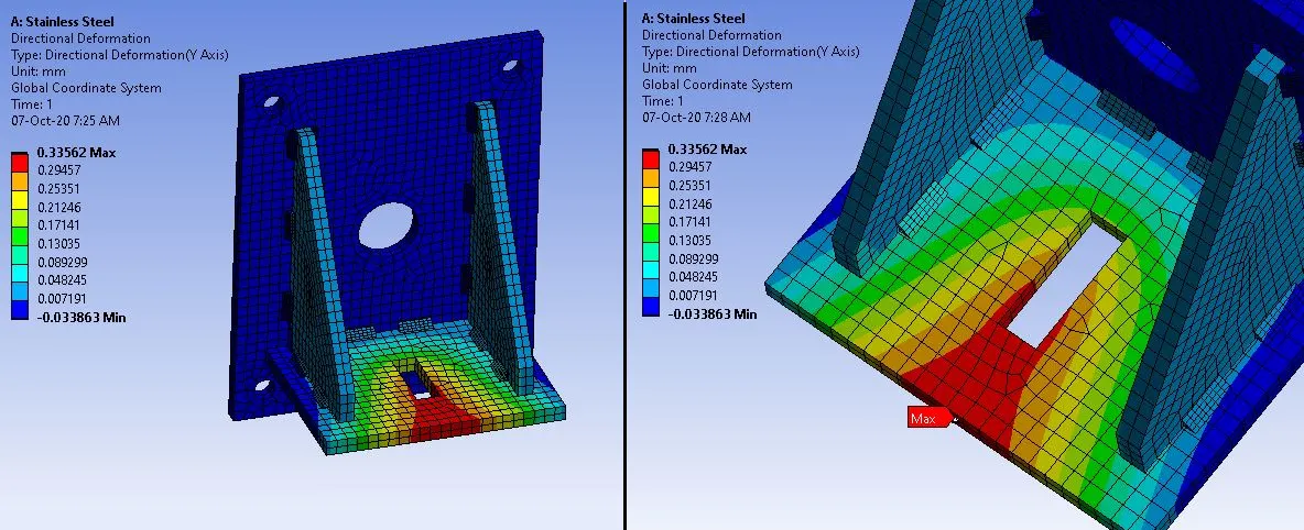
Case_1: Stainless Steel (for Plates, Ribs and Weldments)
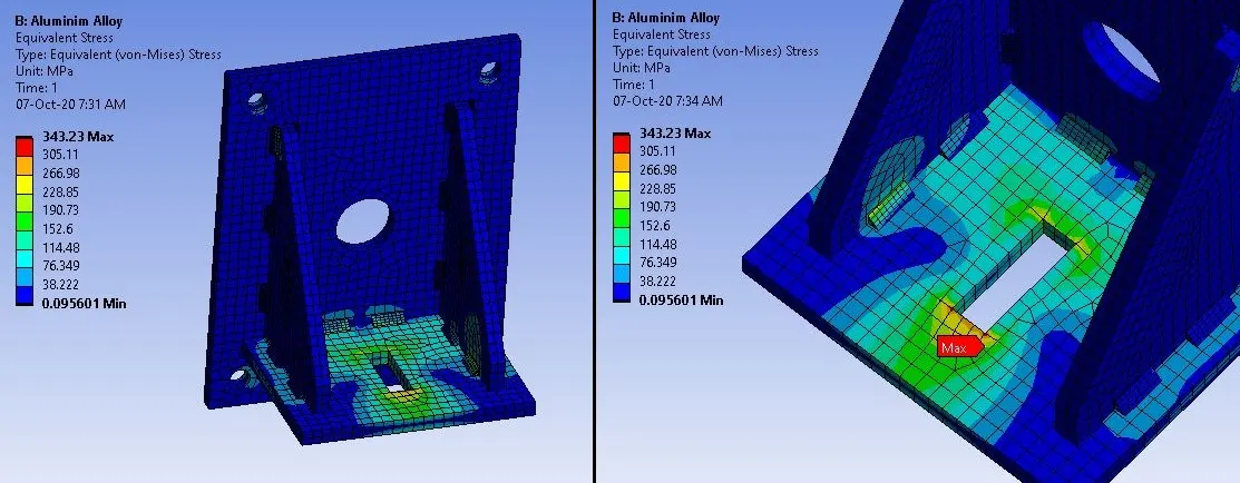
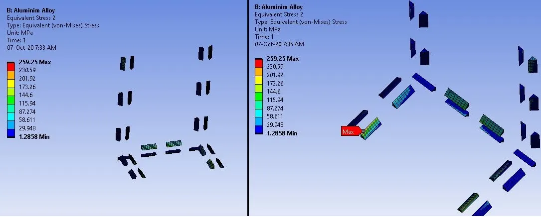
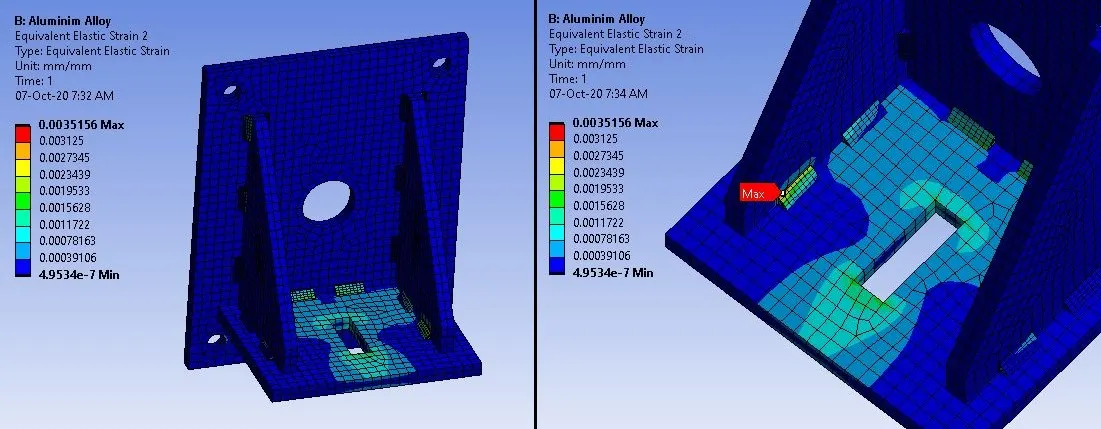
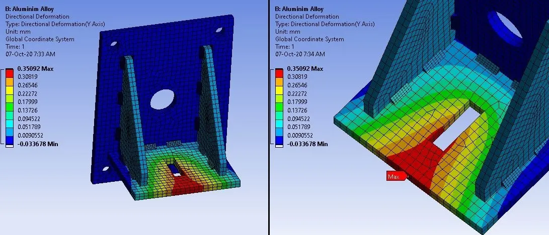
Case_2: Aluminium Alloy (high strength, wrought) for Weldments, (Stainless Steel for Plates & Ribs)
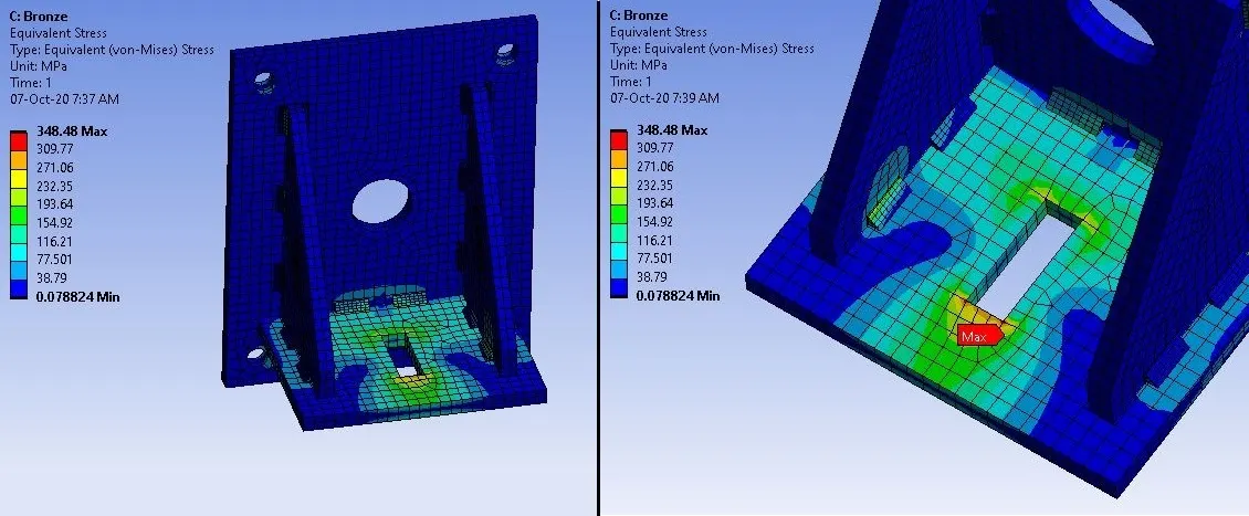
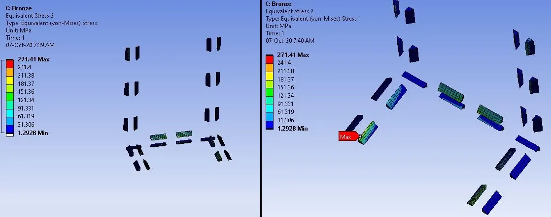
Case_3: Bronze Cast for Weldments (Stainless Steel for Plates, Copper Cast for Ribs)
______________________________________________________________________________________________________________________________________
Geometry:
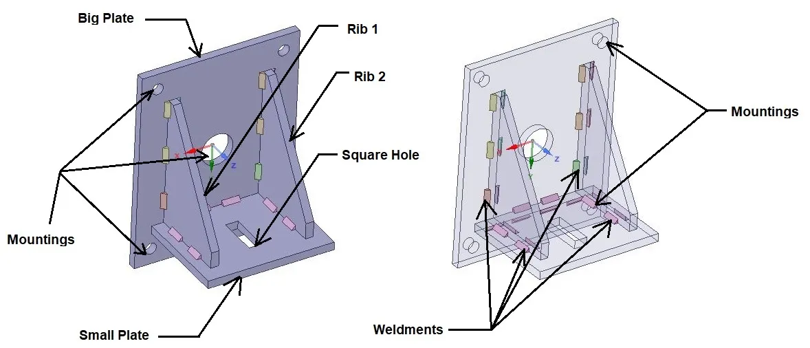
- Plates, Ribs, Weldments and mountings are described for geometry as given below:
______________________________________________________________________________________________________________________________________
Material Specifications:
Stainless Steel:
Density: 7750 Kg/m3
Young’s Modulus: 193000 MPa
Poisson’s Ratio: 0.31
Tensile Yield Strength: 207 MPa
Tensile Ultimate Strength: 586 Mpa
Aluminium Alloy (high strength, wrought):
Density: 2770 Kg/m3
Young’s Modulus: 73800 MPa
Poisson’s Ratio: 0.337
Tensile Yield Strength: 363 MPa
Tensile Ultimate Strength: 449 Mpa
Copper Cast:
Density: 8940 Kg/m3
Young’s Modulus: 125000 MPa
Poisson’s Ratio: 0.345
Tensile Yield Strength: 33.5 MPa
Tensile Ultimate Strength: 152 Mpa
Bronze Cast:
Density: 8810 Kg/m3
Young’s Modulus: 80000 MPa
Poisson’s Ratio: 0.345
Tensile Yield Strength: 144 MPa
Tensile Ultimate Strength: 267 Mpa
______________________________________________________________________________________________________________________________________
Mesh:
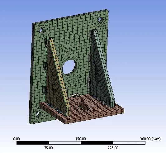
Details:
- Global Element Size: Default
- Body Sizing : Big Plate & Small Plate
Element Size = 7 mm
- Body Sizing : Ribs
Element Size = 7 mm
- No. of Nodes: 30011
- No. of Elements: 4858
______________________________________________________________________________________________________________________________________
Procedure:
- Import model in Static Structural named as “Skill_lync_Welding.stp” in Geometry section.
- Then go to Mechanical model section.
- Rename plates and ribs as Big Plate, Small Plate, Rib 1 and Rib 2 as shown above in geometry.
Connections:
- Delete automatically created contacts and create new contacts as given below:
Contact_1:
Contact Body = Big_Plate
Target Body = Small_Plate
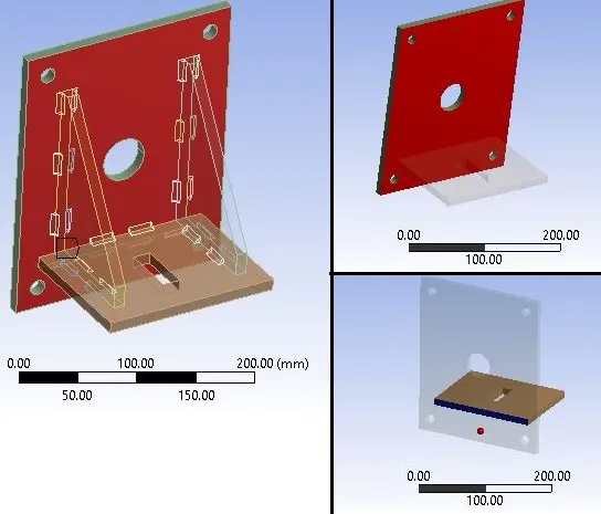
Contact_2:
Contact Body = Big_Plate
Target Body = Rib_1
Contact_3:
Contact Body = Big_Plate
Target Body = Rib_2
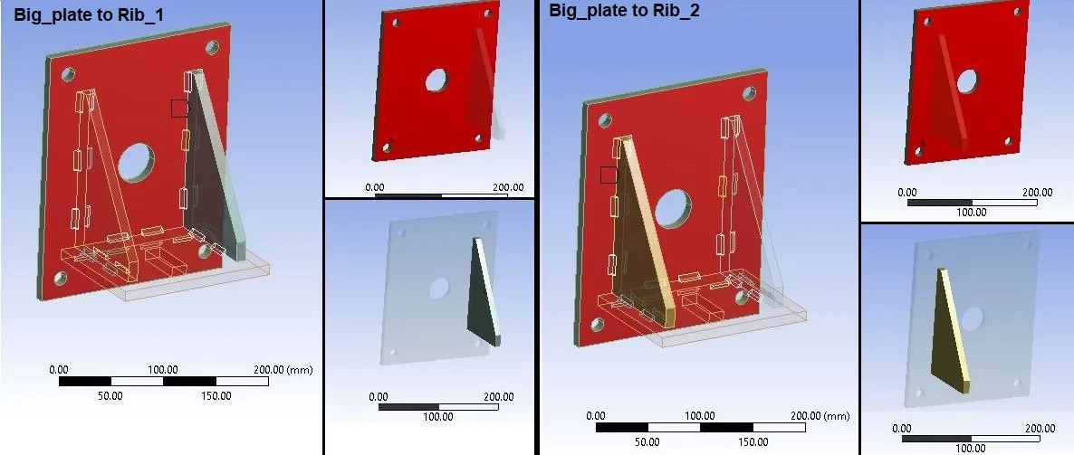
Contact_4:
Contact Body = Small_Plate
Target Body = Rib_1
Contact_5:
Contact Body = Small_Plate
Target Body = Rib_2
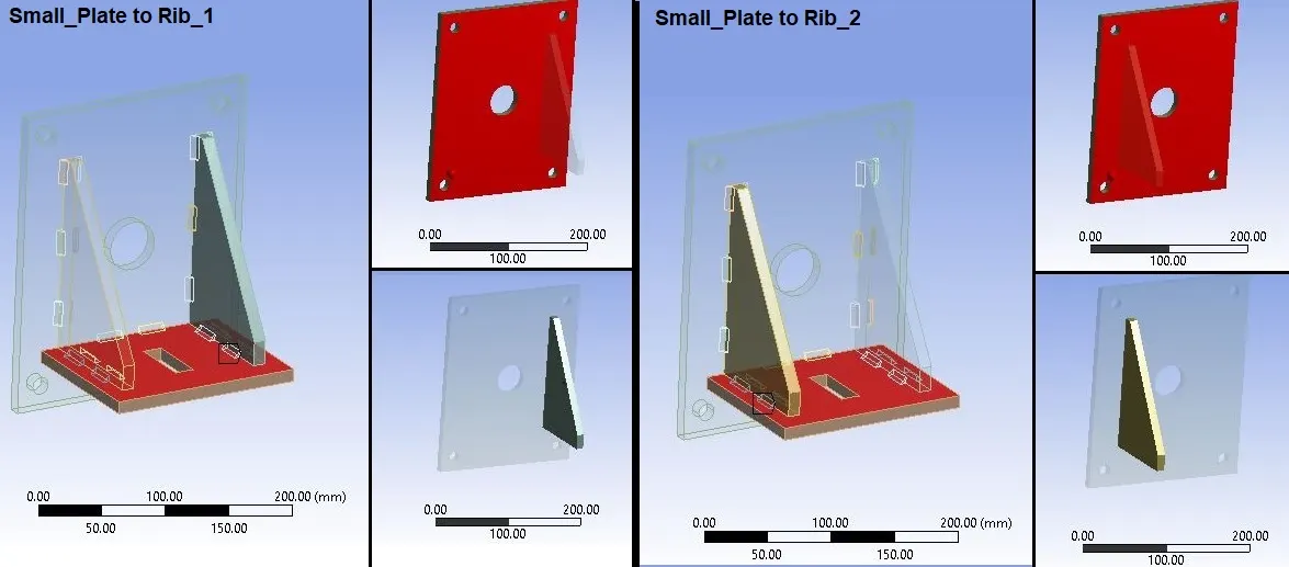
Settings for all Plates and Ribs Contacts:
Type: Frictional
Friction Coefficient: 0.2
Other Contacts:
Contact Body = Assembly
Target Body = Welds
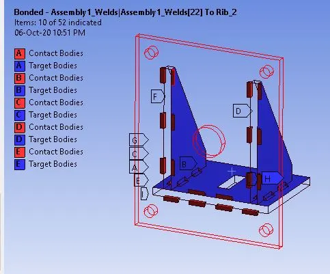
Settings for Weld Contacts:
Type: Bonded
Boundary Conditions:
- After meshing as described above, create Boundary Conditions as given below:
Analysis Settings:
- Auto Time Stepping : Program Controlled
- Solver Type: Program Controlled
- Large Deflection: ON
Here, “Large Deflection = on”, in case we move to non-linear region. So we will be able to capture non-linearities in the model.
Fixed Support:
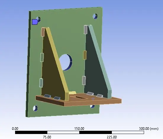
- Apply fixed support to 4 small round holes and 1 big hole as shown in below image:
Force:
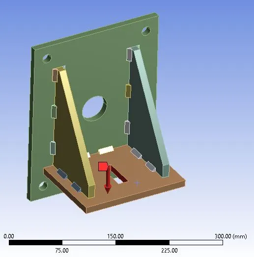
- Apply force to the Square hole in Small Plate of 15000 N (Ramped) in Y-Direction as shown in below image:
Solution:
- After giving proper boundary conditions, create desired solutions for output results.
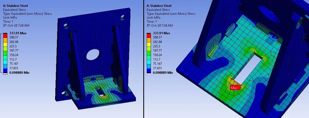
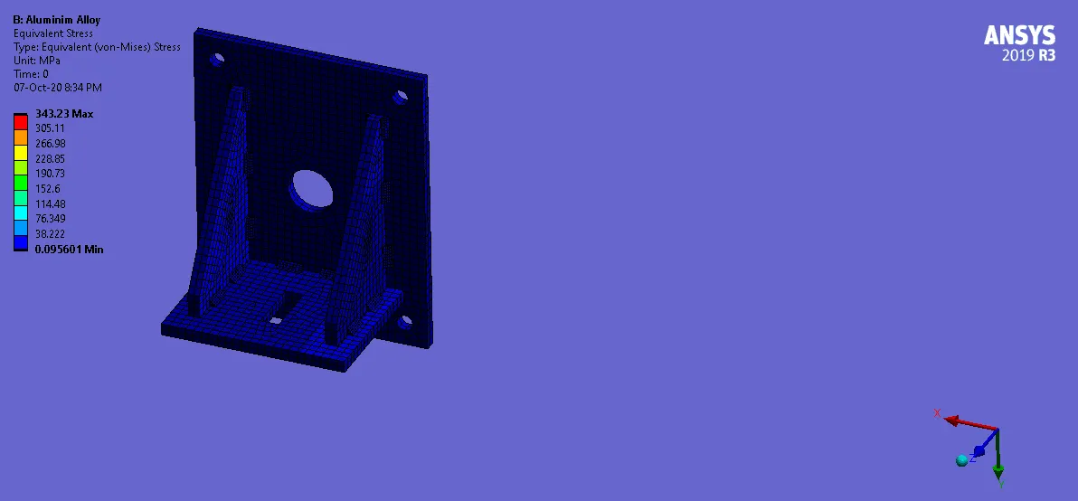
- Create Solutions for “Equivalent (Von Mises) Stress” for all bodies.
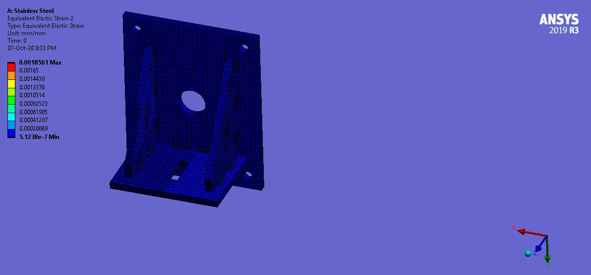
- Create Solutions for “Equivalent (Von Mises) Strain” for all bodies.
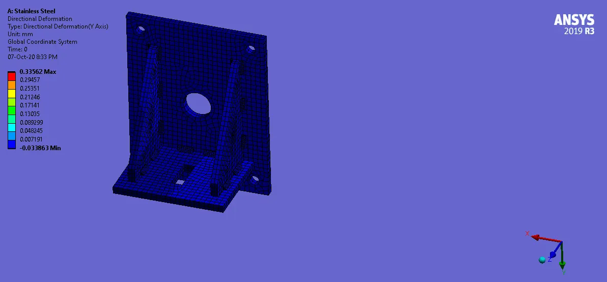
- Create Solutions for “Directional Deformation” and give orientation to Y-Direction for results for all bodies.
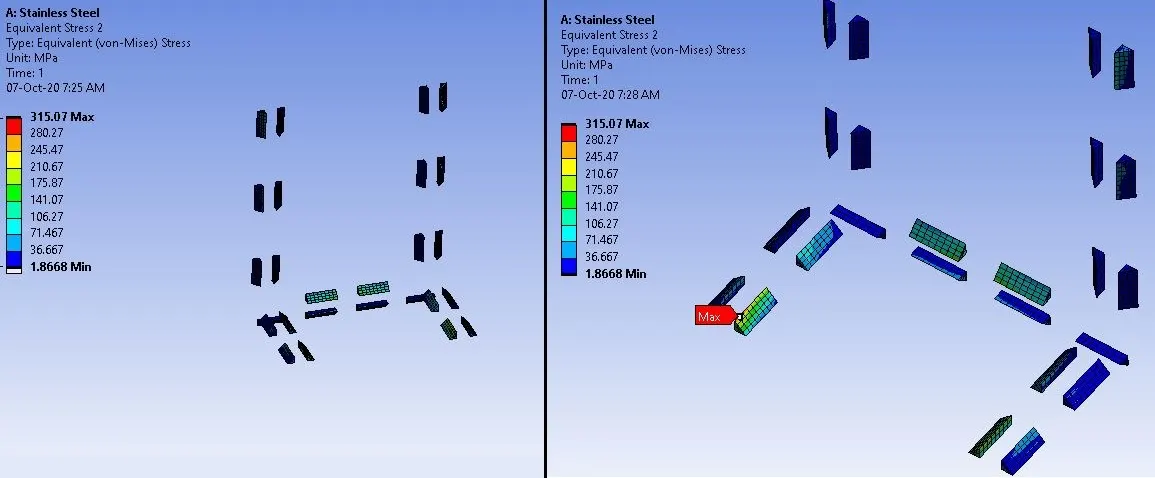
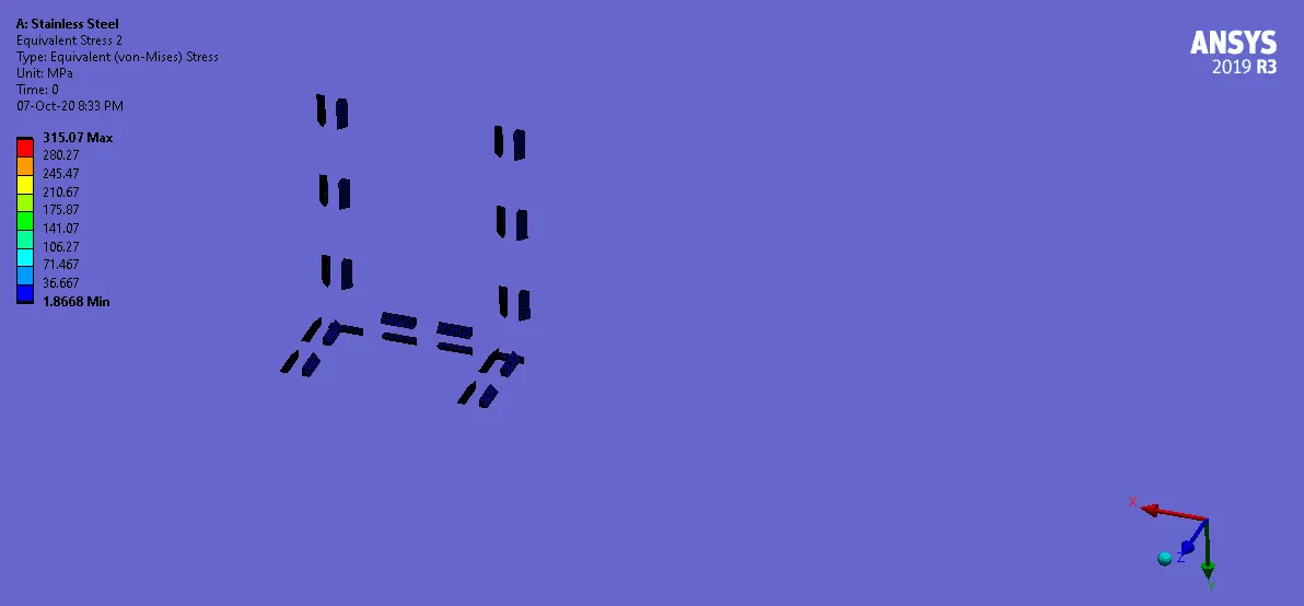
- Create Solutions for “Equivalent (Von Mises) Stress” for all Weldments.
- Solve or Evaluate for solutions.
______________________________________________________________________________________________________________________________________
Results:
- Now we will see the results for all three cases.
CASE_1:
Stress Contours:
Stress Contours for Weldments:
Strains:
Deformation in Y-Direction:
_ _ _ _ _ _ _ _ _ _ _ _ _ _ _ _ _ _ _ _ _ _ _ _ _ _ _ _ _ _ _ _ _ _ _ _ _ _ _ _ _ _ _ _ _ _ _ _ _ _ _ _ _ _ _ _ _ _ _ _ _ _ _ _ _ _ _ _ _ _ _ _ _ _ _ _ _ _ _ _ _
CASE_2:
Stress Contours:
Stress Contours for Weldments:
Strains:
Deformation in Y-Direction:
_ _ _ _ _ _ _ _ _ _ _ _ _ _ _ _ _ _ _ _ _ _ _ _ _ _ _ _ _ _ _ _ _ _ _ _ _ _ _ _ _ _ _ _ _ _ _ _ _ _ _ _ _ _ _ _ _ _ _ _ _ _ _ _ _ _ _ _ _ _ _ _ _ _ _ _ _ _ _ _ _
CASE_3: (Brazing)
Stress Contours:
Stress Contours for Weldments:
Strains:
Deformation in Y-Direction:
______________________________________________________________________________________________________________________________________
Comparison:
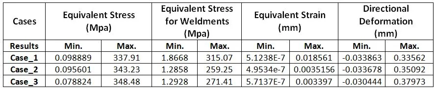
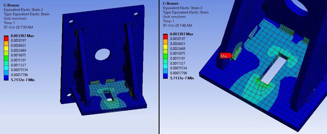
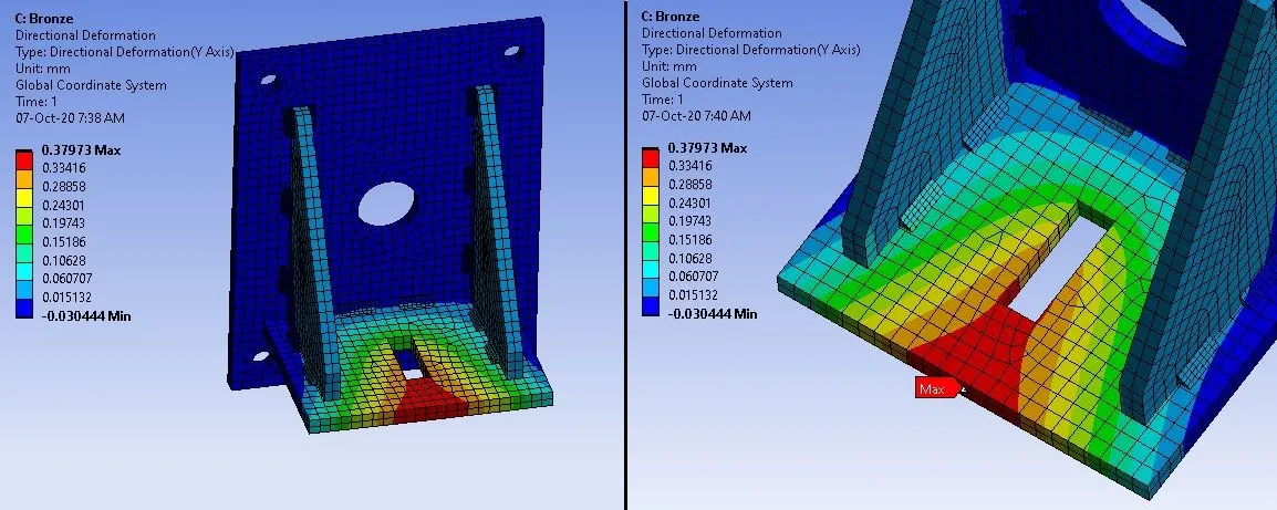
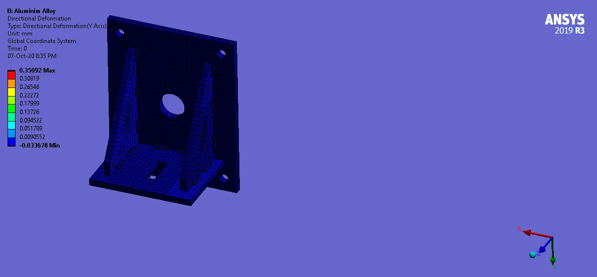
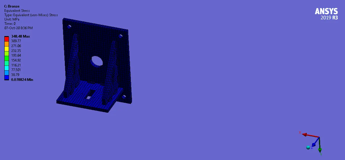
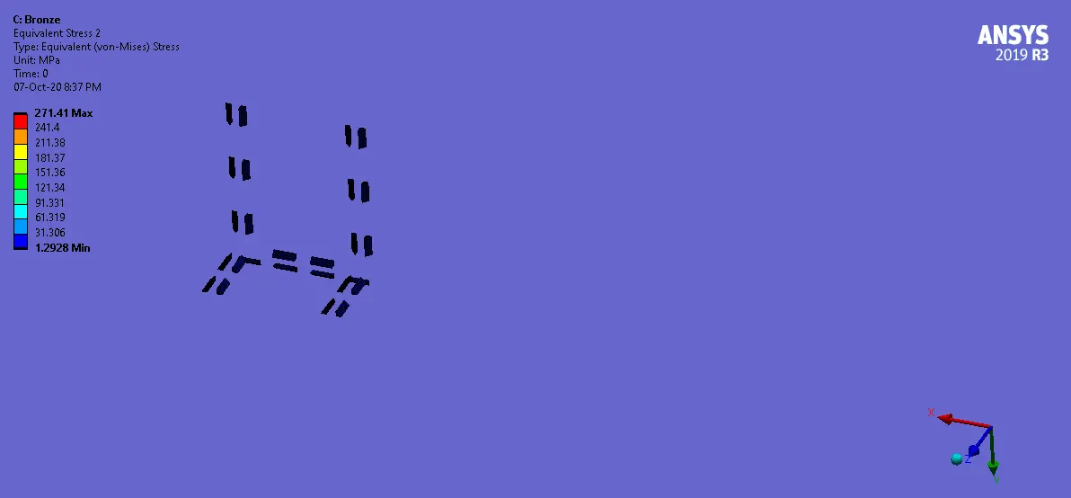
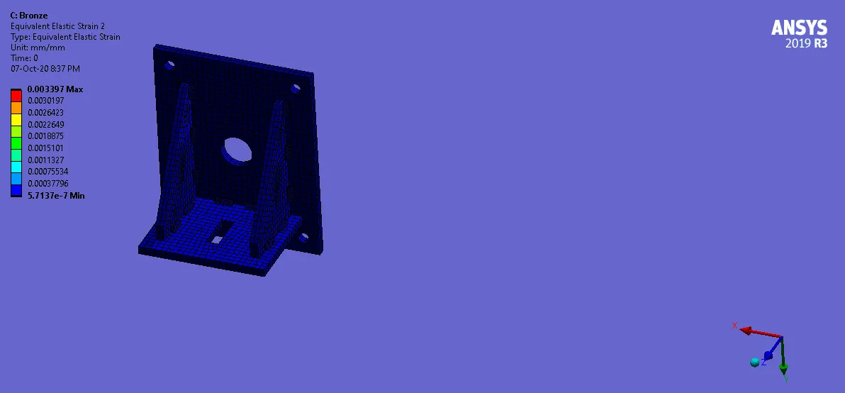
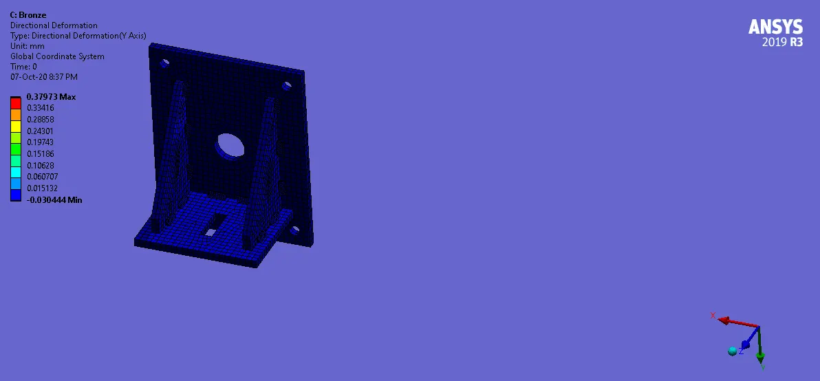
- As shown in table, Directional Deformation is Maximum in this case. This is due to lower Yield Strength. Also we can see from strain contours, which have maximum strain at weld joint. So due to lower strength, and high stress and high strain at weld joint, it cannot withstand the load and failure can occur. Also we can see that maximum deformation occurs at the square location in all cases, so Weldment 20, near the square hole will be more affected and brazing with ribs can be removed or deformed.
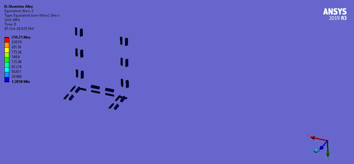
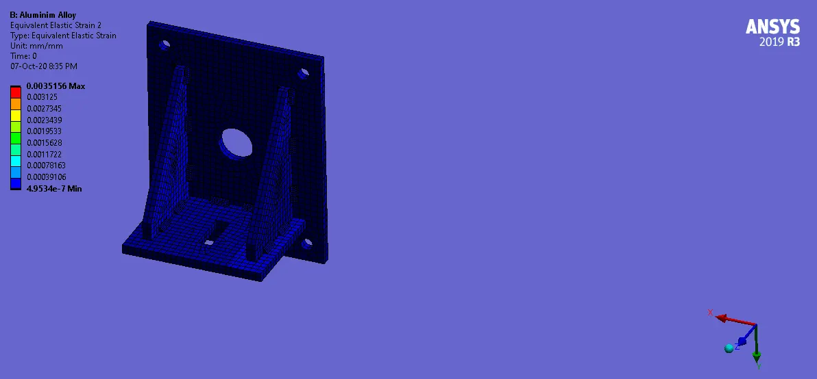
- If we observe maximum strain, then it is highest in CASE_2. This is because Aluminimum Allou (Strength, wrought) has lowest Modulus of elasticity among all materials. So at lower modulus of elasticity, strain will always high.
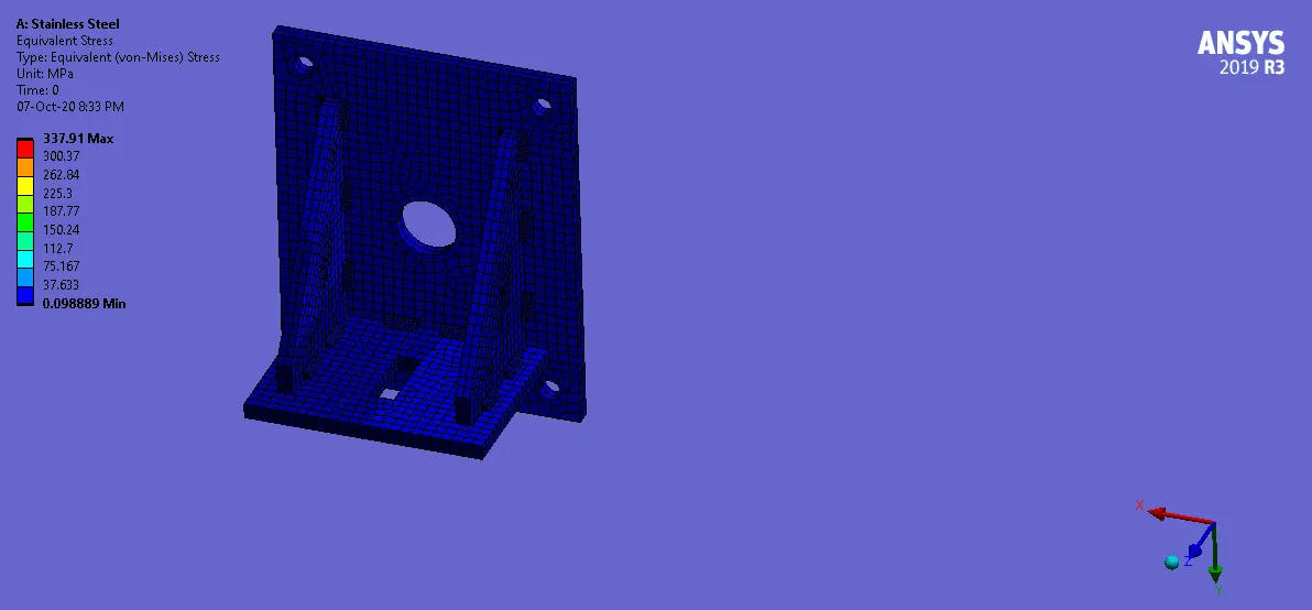
- We can observe from the contours that Maximum Equivalent Stress is Maximum in CASE_1 where all the components are made of Stain less Steel.
________________________________________________________________________________________________________________________
Conclusion:
- As we have seen the Brazing in CASE_3. Brazing has many advantages over other metal joining techniques, because it does not melt the base metal, less thermal distortion and capability of joining two different materials. But the main disadvantage is lack of joint strength. Strength of brazed joint is likely to be less than base metals. Also it can be damaged under high service temperatures.
- Aluminium alloys are used in fabrication because of their low weight, good corrosion resistance and good Weldability. So for welding Aluminium alloys, filler material like Aluminium Alloy (high strength, wrought) is acceptable.
- Steel material for welding can also be used. As we know, for MIG welding, carbon steel and stainless steel are used as ideal materials.
- So depending upon the needs of strength, Weldability and availability and cost of material, and based on type of welding process, we can choose different material for weld joint.
________________________________________________________________________________________________________________________
References:
- https://en.wikipedia.org/wiki/Welding_joint
- https://en.wikipedia.org/wiki/Welding
- https://en.wikipedia.org/wiki/Brazing
- https://www.twi-global.com/technical-knowledge/faqs/what-is-welding
- https://www.twi-global.com/technical-knowledge/faqs/faq-what-is-brazing
- https://www.industrialmetalsupply.com/blog/what-metals-can-be-welded
________________________________________________________________________________________________________________________
Animations:
CASE_1:
Stress:
Stress on Weldments:
Strain:
Deformation in Y-Direction:
_ _ _ _ _ _ _ _ _ _ _ _ _ _ _ _ _ _ _ _ _ _ _ _ _ _ _ _ _ _ _ _ _ _ _ _ _ _ _ _ _ _ _ _ _ _ _ _ _ _ _ _ _ _ _ _ _ _ _ _ _ _ _ _ _ _ _ _ _ _ _ _
CASE_2:
Stress:
Stress on Weldments:
Strain:
Deformation in Y-Direction:
_ _ _ _ _ _ _ _ _ _ _ _ _ _ _ _ _ _ _ _ _ _ _ _ _ _ _ _ _ _ _ _ _ _ _ _ _ _ _ _ _ _ _ _ _ _ _ _ _ _ _ _ _ _ _ _ _ _ _ _ _ _ _ _ _ _ _ _ _ _ _ _
CASE_3 (Brazing):
Stress:
Stress on Weldments:
Strain:
Deformation in Y-Direction:
___________________________________________________________________________________________________________
Thanks & Regards,
Dharmesh Joshi