Week 3 - 2D meshing for sheet metal

Introduction:
The hood (North American English) or bonnet (Commonwealth English) is the hinged cover over the engine of motor vehicles. Hoods can open to allow access to the engine compartment, or trunk (boot in Commonwealth English) on rear-engine and some mid-engine vehicles) for maintenance and repair.
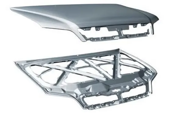
In recent years, the work has been done on the bumper and hood design of the vehicle front end to reduce the injuries to the pedestrians in the event of a pedestrian vehicle collision. The front portion of the vehicle gets damaged including bonnet when met with an accident. So there is need to change the existing design of bonnet or by changing the material. The bonnet is the hinged cover over the engine of motor vehicles that allows access to the engine compartment for maintenance and repair. Bonnet usually do not directly open onto the passenger cell which greatly reduces the importance (weighting) of certain of the functional requirements normally associated with closures such as air tightness, passenger safety, low cycle fatigue strength etc. The objective of these measures is to reduce the number of road accident fatalities and the severity of injuries sustained by pedestrians involved in a collision with a vehicle in urban traffic. Impact frequency and seriousness of injury has been studied for many years, resulting in rating systems and improved design. The bonnet system is an access panel to the engine compartment to enable maintenance of power train, drive belts, battery, fluid levels and lamp units. It is fundamentally a reinforced skin panel with many Safety and quality requirements.
Engine Hood:
The hood which is also known as ENCON, serves as an access panel to engine compartment of an Automobile. It is an assembly made of Outer and Inner panels to meet various safety and design requirements.
The followings are the design considerations involved in the design of Engine Hood.
- Pedestrian Safety
- Vehicle quality
- Occupant Safety
- Styling
- Manufacturability
Types of Hoods:
- Invalid Hood or Built IN
- Wrap Around Hood
- Hood With Fenders
- Hood with Border Diagonal Frames
- Hood with Brace Frames
_____________________________________________________________________________________________________________________
Meshing of Hood:
Here we will see the Meshing of different parts of Hood.
Hood consists four different components as below:
- Inner Extract
- Outer Extract
- Hinge Reinforcement Extract
- Latch Reinforcement Extract
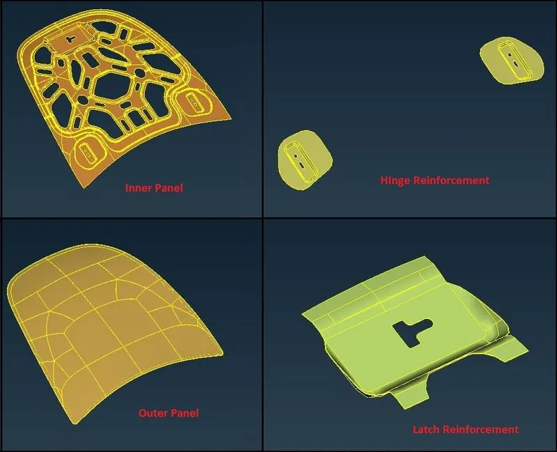
As shown in above image, there are four different components.
In this paper, meshing of these four components is described one by one.
Quality Criteria:
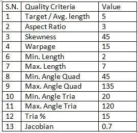
Quality Criteria for the Meshing of all the components are given as below:
_____________________________________________________________________________________________________________________
Procedure:
Geometry Cleanup:
- After importing the geometry, first of all geometry check should be done.
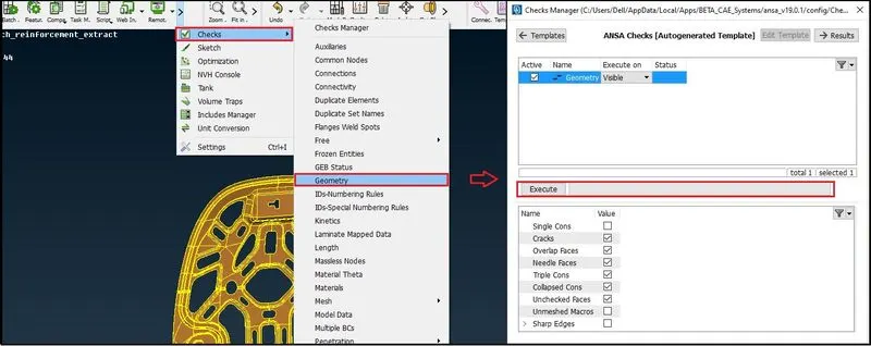
- As shown in above image, select Tools > Geometry .
- Select necessary options to check and select “Execute”.
- Ansa will check all possible errors and discontinuity in the model.
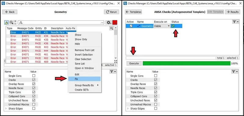
- As we can see in above image, if there are any errors related to geometry, it will be shown in window.
- Fix the geometry be checking one by one or else we can also use “Fix” option to directly fix the errors.
- After removing of errors and correcting them, again select “Execute”.
- If the model has no error, it will show green status as in above image and we can proceed further.
Midsurface Creation:
Inner Panel:
- First of all check the orientation of the surfaces and correct the orientation for the model.
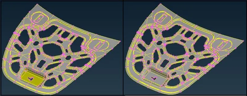
- As shown in above image, orientation is corrected for the model.
- Measure the thickness of the component.
- Offset the faces to create the midsurface at the distance half of the thickness as shown in below image.
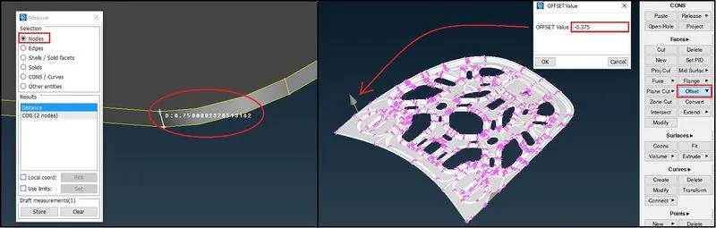
- As in above image, select Faces> offset> Select Faces > Offset Value.
- Here negative value is given to generate the midsurface in the direction opposite to shown in above image.
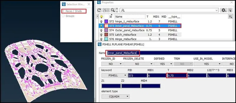
- Create Part ID with Faces > Set PID option and property as “PSHELL”. Also give thickness as per component as shown in above image.
- Since the model is mostly symmetric, remove half of the portion and keep only unsymmetrical portion to mesh.
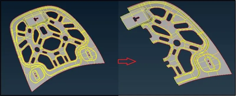
- After creating midsurface, set all necessary quality criteria for the mesh.
- In the Mesh module, Set the length of the perimeter as 5 units as shown below.
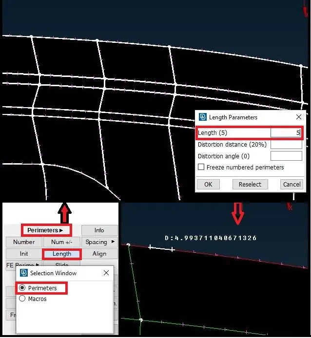
- Select Length > Perimeters > Select all boundaries > Apply Length = 5.
- After giving 5 unit lengths, we can see the distance between points on the perimeter, has been set neat 5 unit of length approximately.
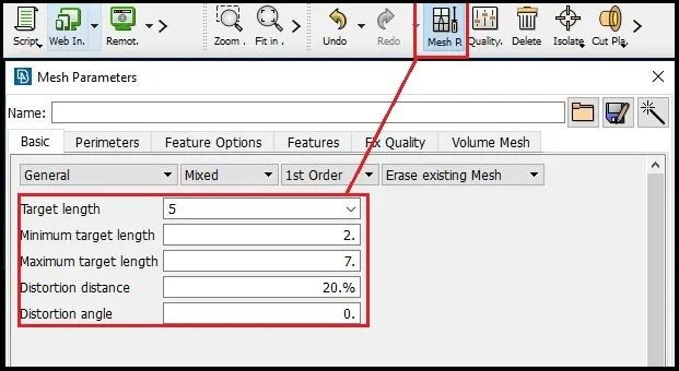
- Give Mesh Parameters as shown in above image for better meshing.
- After all necessary parameters, we can proceed for meshing the component.
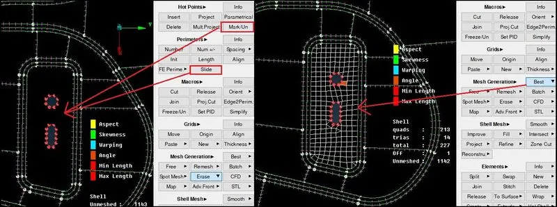
- Before meshing, check and set the holes for better orientation for better mesh flow as shown in above image.
- To do that, select > Perimeters > Slide > select hole perimeter.
- After sliding it in proper orientation, select > Hot Ponts > Mark / Un for licking its perimeter.
- After that, in Mesh Generation panel, Select “Best” and select face to be meshed.
- Thus start the meshing of the areas with less free edges and proceed to the boundaries for good meshing.
- And avoid washer surfaces if possible.
- Keep the Mesh flow as per geometry and create mesh with less tria elements.
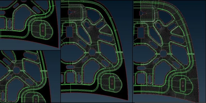
- As shown in above image, step by step create the mesh from inner to outer regions and keep the mesh flow as good as possible.
- After completing the half portion of the mesh, copy the elements with symmetry option as below:
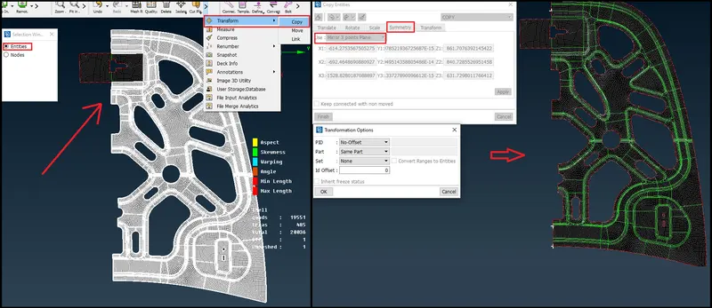
- Select the entities to be reflected only.
- Using 3 point, reflect the mesh and faces.
- Make sure the other portion is removed so that there will be no duplicate faces.
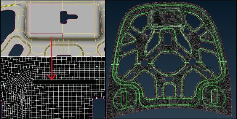
- After reflection, there will be some free cons.
- That must be corrected for proper connection.
- Use Faces > Topo > Select Cons. And correct the edges for connection.
- Due to that correction, as shown in above image, some elements will be deleted.
- So, in that portion again create remaining mesh.
- Thus we can complete the Mesh model as shown in above image.
_ _ _ _ _ _ _ _ _ _ _ _ _ _ _ _ _ _ _ _ _ _ _ _ _ _ _ _ _ _ _ _ _ _ _ _ _ _ _ _ _ _ _ _ _ _ _ _ _ _ _ _ _ _ _ _ _ _ _ _ _ _ _ _ _ _ _ _ _ _ _ _
Outer Panel:
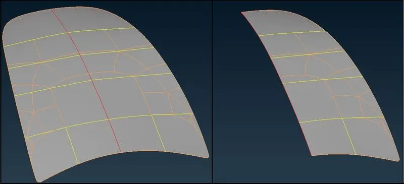
- Here we can see the component is axis symmetric, so we can cut it into half.
- Create Midsurface by using “Offset” faces option as described for Inner Panel.
- Also create Property and give thickness.
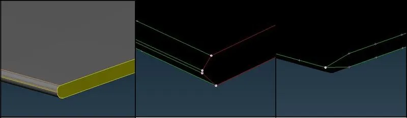
- As shown in above image, the hemming portion of the component is very thin.
- So, after creating midsurface, we can toggle the extra edges and split the component from the curvature area as shown in above image and easily create mesh without minimum length element.
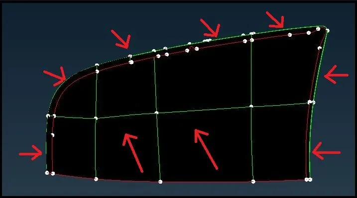
- For easy and structured mesh, create rectangular portions by splitting the geometry with lines as shown in above image.
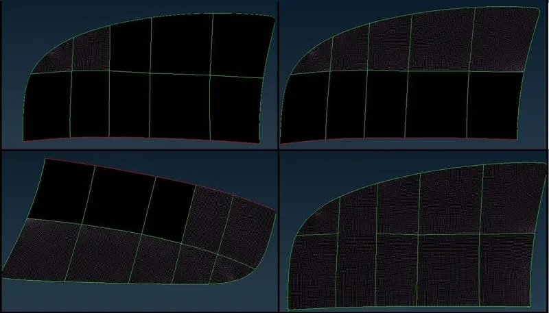
- Start with the curved or radius portion to avoid minimum length elements and step by step create mesh as shown in above image.
- We can further divide the curved portion marked in above image and create better quality elements in that region.
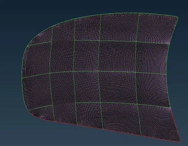
- Reflect the Mesh with symmetry option and check for connectivity.
- Thus we can complete the Mesh of “Outer Extract” component with better mesh flow.
_ _ _ _ _ _ _ _ _ _ _ _ _ _ _ _ _ _ _ _ _ _ _ _ _ _ _ _ _ _ _ _ _ _ _ _ _ _ _ _ _ _ _ _ _ _ _ _ _ _ _ _ _ _ _ _ _ _ _ _ _ _ _ _ _ _ _ _ _ _ _ _
Latch Reinforcement:
- Perform Geometry Check for Latch Reinforcement.
- Create Midsurface as above described.
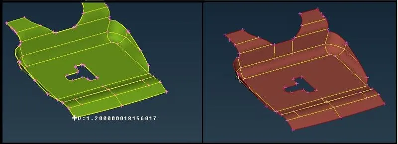
- As shown in above image, midsurface is created at 0.6 unit distance.
- Also create Property and give thickness.
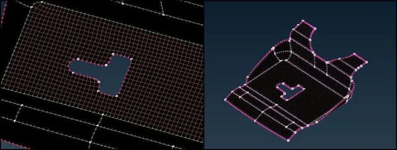
- Keep the mesh flow as per geometry.
- Avoid tria elements at the free edges.
- As shown in above image, create mesh at the centre first and then proceed further for good mesh and complete the entire mesh for Latch Reinforcement extract.
_ _ _ _ _ _ _ _ _ _ _ _ _ _ _ _ _ _ _ _ _ _ _ _ _ _ _ _ _ _ _ _ _ _ _ _ _ _ _ _ _ _ _ _ _ _ _ _ _ _ _ _ _ _ _ _ _ _ _ _ _ _ _ _ _ _ _ _ _ _ _ _
Hinge Reinforcement:
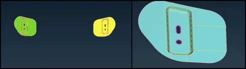
- Here there are two components in Hinge Reinforcement.
- If we create mesh only for one, we can reflect it on other.
- So, create midsurface for only one part at 0.6 unit distance.
- Also create Property and give thickness.
- As shown in above image, avoid creating washer surface for the holes for better mesh arrangement.
- Toggle the edges where minimum length element can occur.
- Also divide the face as per convenience and for better mesh flow.
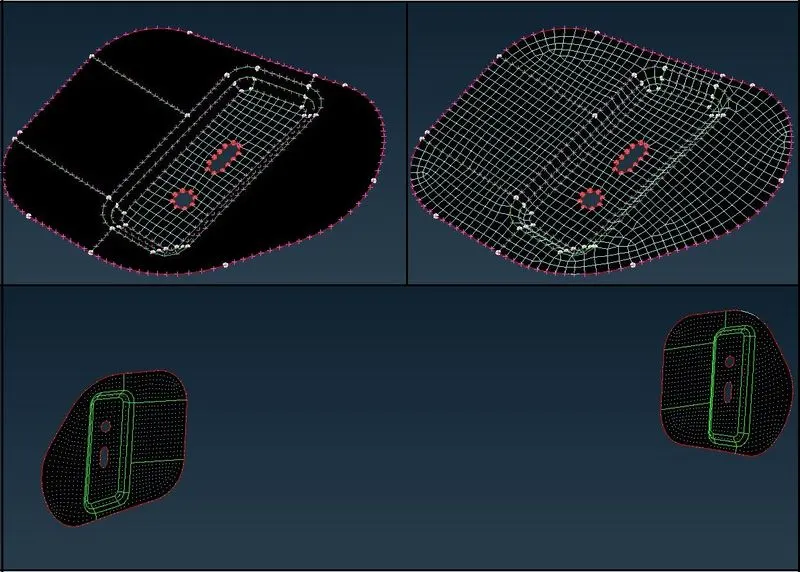
- As shown in above image, mesh is created at the inner most area where less free edges are there.
- Then followed by them, rest of the part is meshed.
_____________________________________________________________________________________________________________________
Mesh Results:
Inner Panel:
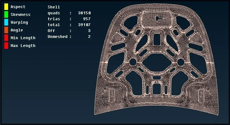
- Tria % = 2.44
Outer Panel:
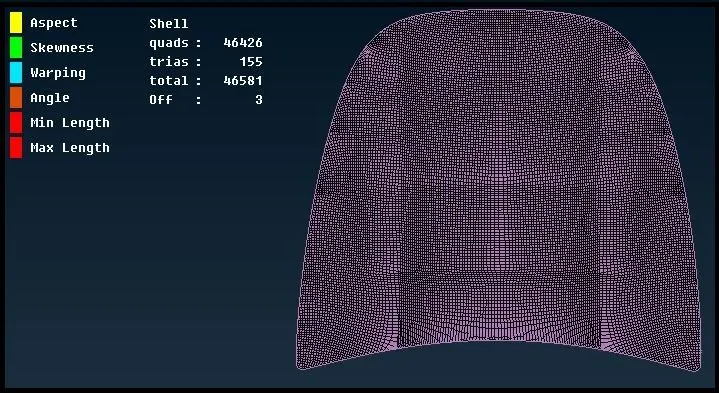
- Tria % = 0.33
Latch Reinforcement:
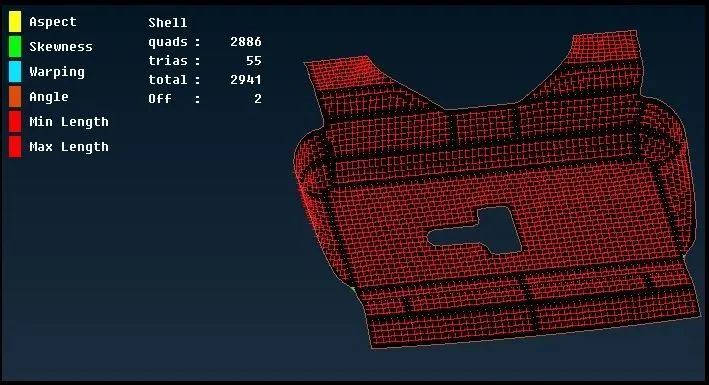
- Tria % = 1.87
Hinge Reinforcement:
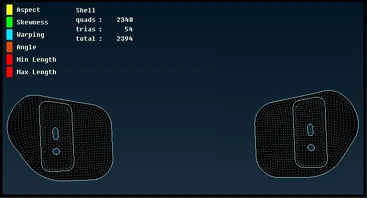
- Tria % = 2.25
_____________________________________________________________________________________________________________________
Inference:
- First thing to do with any given model is geometry check and removing or toggling extra edges or lines and any discontinuity or errors.
- For good meshing, we should always take care of necessary lines and edges by which we can create easy and structured mesh.
- If there is small gap between two fillets, we can toggle one of the edges and simplified the meshing area to avoid minimum or maximum length elements.
- Important thing in meshing is mesh flow, which should be followed by the given geometry.
- We should avoid as much tria elements as possible.
- There should not be any rotational quads, which can disorient the analysis process and we can get poor results.
- We cannot avoid tria elements at the rounded or curved portions, so the elements at that area should be taken care with different splitting the surface.
- Make sure that tria elements do not break the flow of the mesh and percentage amount of tria elements should be within the limit..
- Thus, we can create good mesh with good arrangements of tria and quad elements with proper flow and reconstruction and smoothing techniques.
________________________________________________________________________________________________________
Thanks & Regards,
Dharmesh Joshi