Week 1 Stress Concentration on a Plate with hole

Introduction
The elements, which are used for machining purposes offered with geometrical
Irregularities, which disturb the stress distribution and therefore, the state of stress in stress concentrated regions, cannot be described in machine elements. Thus, the finite element method (FEM) is an important tool used to analyze the stress. The finite element method (FEM) is a numerical method of analysis for stresses and deformations in structures of any given geometry. The structure is discretized into the so-called ‘finite elements’ connected through nodes. The type, arrangement and a total number of elements affect the accuracy of the results. It is frequently used to solve the difficult engineering problems, mostly in the fields of mechanical, civil, and aeronautical engineering. Also, it is a solution of several other types of engineering problems like heat conduction, fluid dynamics, electric and magnetic fields, structure analysis, solid mechanics, dynamics, thermal analysis, electrical analysis, biomaterials.
______________________________________________________________________________________________________________________________________
Problem Definition:
Here we will see the Analysis in two different cases.
CASE_1: Rectangular Plate with one hole
CASE_2: Rectangular Plate with three holes
- In these analyses, we will fix plate at one end and apply the force of 500 at another end.
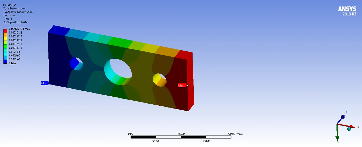
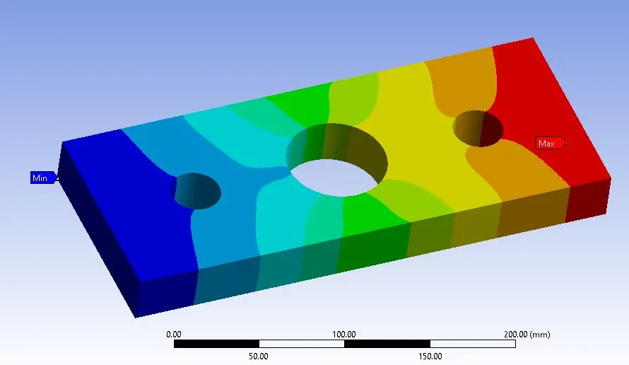
- We will see the Stress induced and Deformation produced due to applied load.
- Also we will see the Analytical method for Stress concentration method as well as FEM method and compare both the results of CASE_1 & CASE_2.
- Then only we can conclude that which design is good as per analysis stand point and which design is good for Manufacturing stand point.
______________________________________________________________________________________________________________________________________
Procedure:
- Open Static Structural in Ansys.
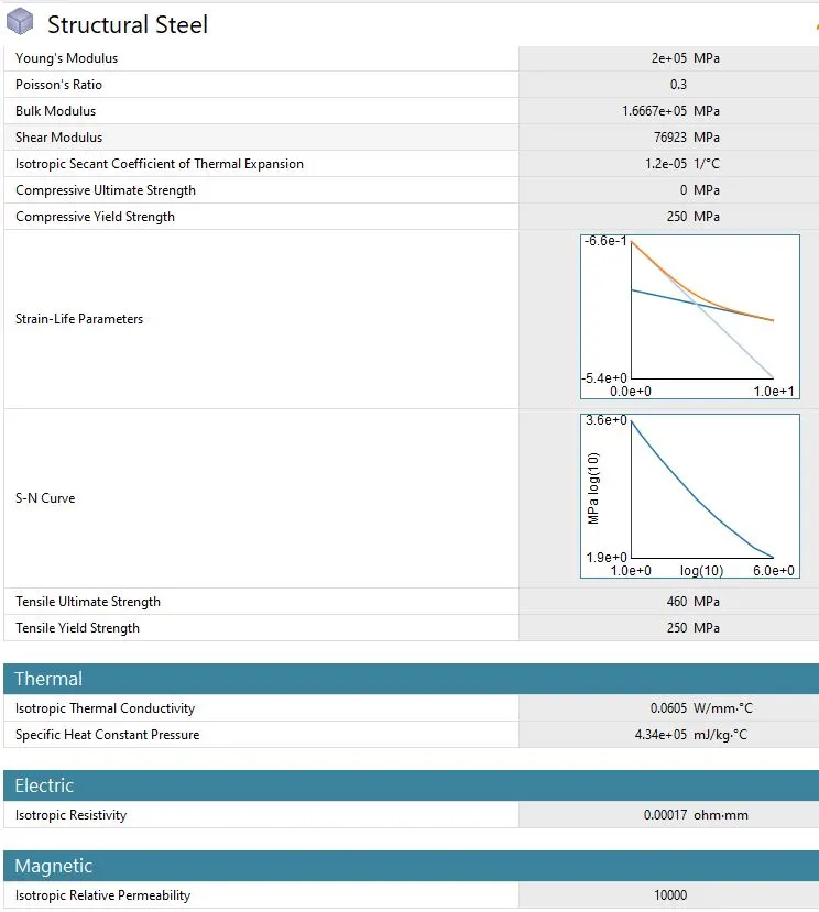
- Material in “Engineering Data” is “Structural Steel”, which is by default.
- Material Specifications for both the cases will remain same.
Material Specifications:
- Open SpaceClaim
- Create geometry as given below:
_ _ _ _ _ _ _ _ _ _ _ _ _ _ _ _ _ _ _ _ _ _ _ _ _ _ _ _ _ _ _ _ _ _ _ _ _ _ _ _ _ _ _ _ _ _ _ _ _ _ _ _ _ _ _ _ _ _ _
CASE_1
Geometry:
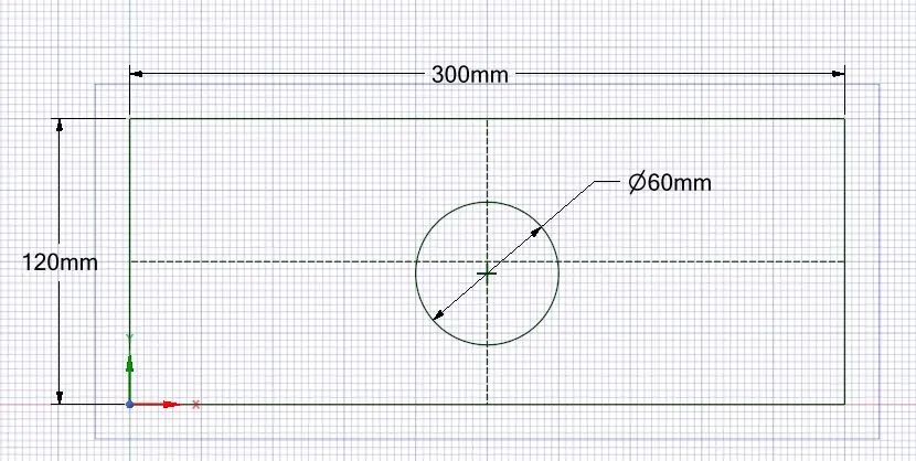
- After crating sketch, delete unnecessary construction line.
- Delete hole surface and Pull the surface up to 30 mm.
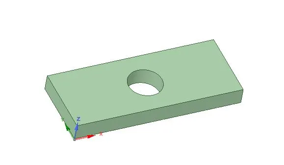
- Finally geometry will look like shown in above image.
Mesh:
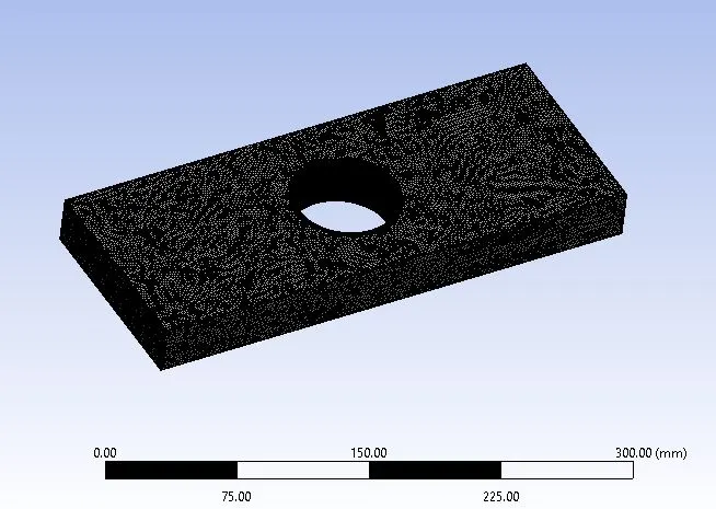
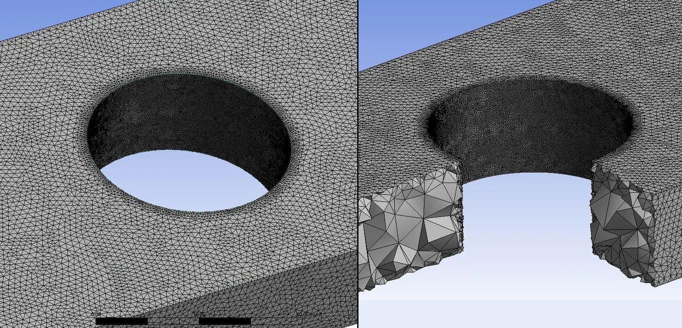
Details:
Element Size: 1 mm
Patch Conforming Method: Tetrahedrons
Refinement: 1
No. Of Nodes: 646460
No. Of Elements: 401415
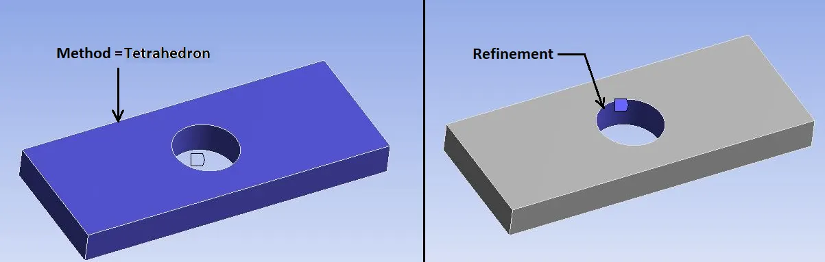
- Here we can create Tetrahedron elements with help of “Patch Conforming Method.
- Also for accuracy near the hole area, we can give Refinement for the hole face.
See the image below:
Boundary Conditions:
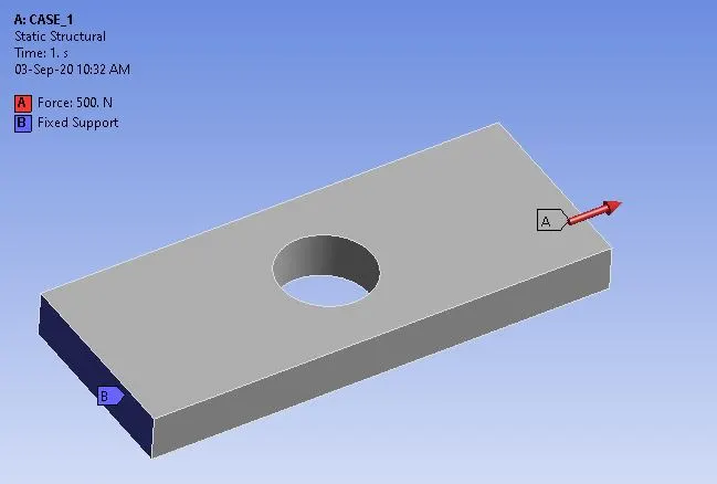
- Here we have given a fixed support at left end face.
- On the other end face we have given Force of 500 N with help of component of Global coordinate system in that direction.
_ _ _ _ _ _ _ _ _ _ _ _ _ _ _ _ _ _ _ _ _ _ _ _ _ _ _ _ _ _ _ _ _ _ _ _ _ _ _ _ _ _ _ _ _ _ _ _ _ _ _ _ _ _ _ _ _ _ _
CASE_2
Geometry:
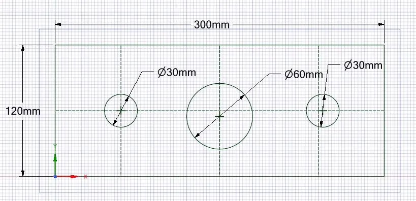
- After crating sketch, delete unnecessary construction line.
- Delete hole surface and Pull the surface up to 30 mm.
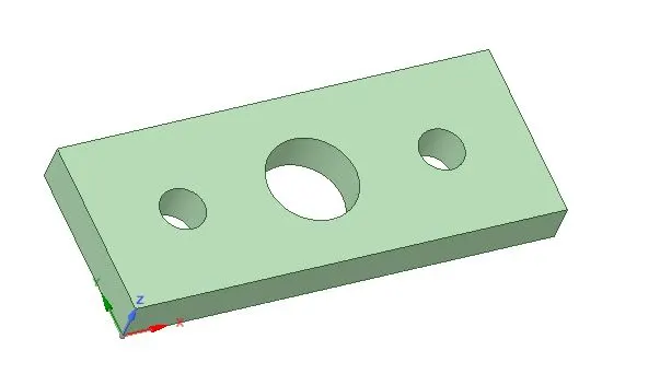
- Finally geometry will look like shown in above image.
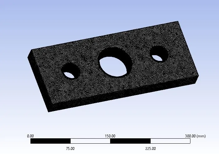
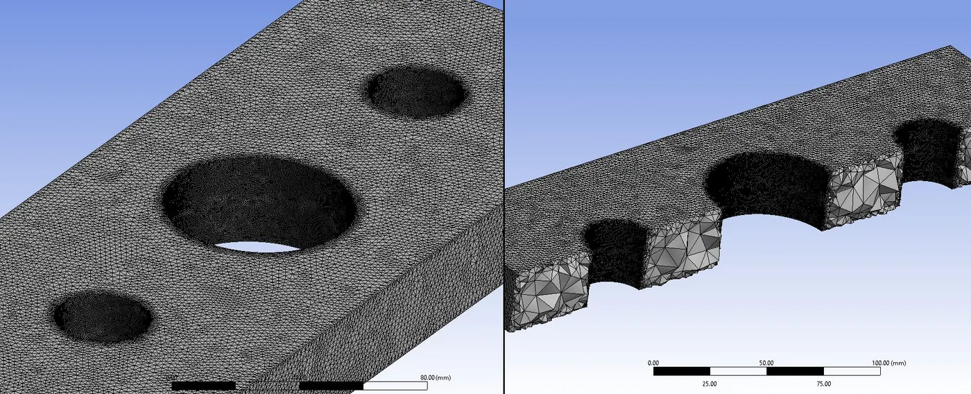
Mesh:
Details:
Element Size: 1 mm
Patch Conforming Method: Tetrahedrons
Refinement: 1
No. Of Nodes: 1028172
No.Of Elements: 650662
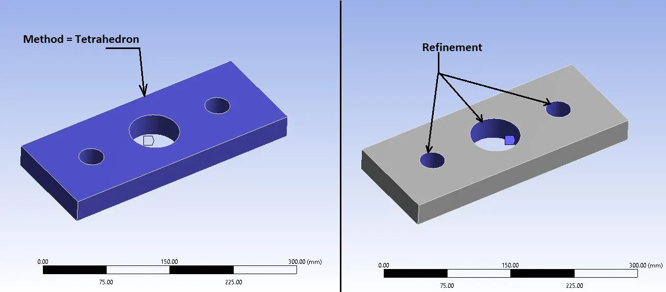
- Here we can create Tetrahedron elements with help of “Patch Conforming Method.
- Also for accuracy near the hole area, we can give Refinement for the hole face.
See the image below:
Boundary Conditions:
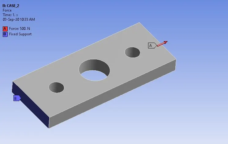
- Here we have given a fixed support at left end face.
- On the other end face we have given Force of 500 N with help of component of Global coordinate system in that direction.
_ _ _ _ _ _ _ _ _ _ _ _ _ _ _ _ _ _ _ _ _ _ _ _ _ _ _ _ _ _ _ _ _ _ _ _ _ _ _ _ _ _ _ _ _ _ _ _ _ _ _ _ _ _ _ _ _ _ _
Solutions:
- After mesh and boundary conditions, we can generate solutions whatever we need from analysis.
- So, we will create output solutions for Stress and Deformation.
- For both the cases, create solutions as “Equivalent (Von-Mises) Stress” and “Total Deformation”
______________________________________________________________________________________________________________________________________
Results:
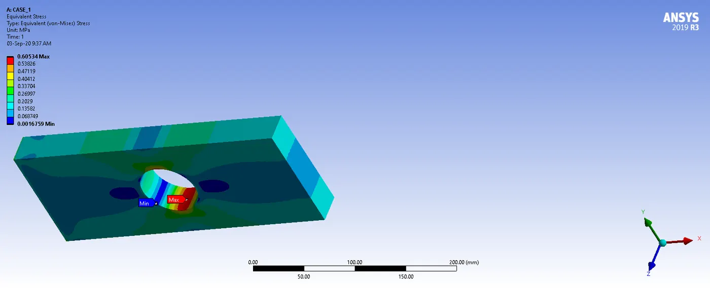
CASE_1
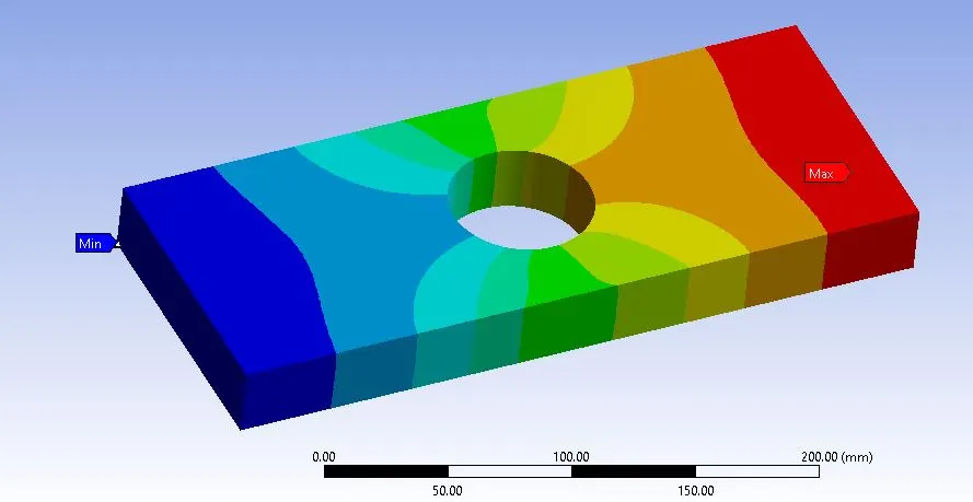
Stress Contours:
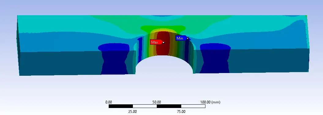
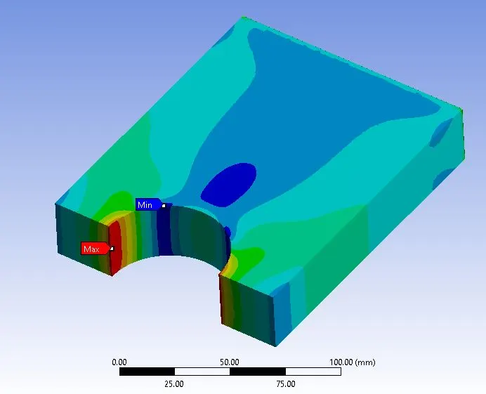
Stress Contours at sections:
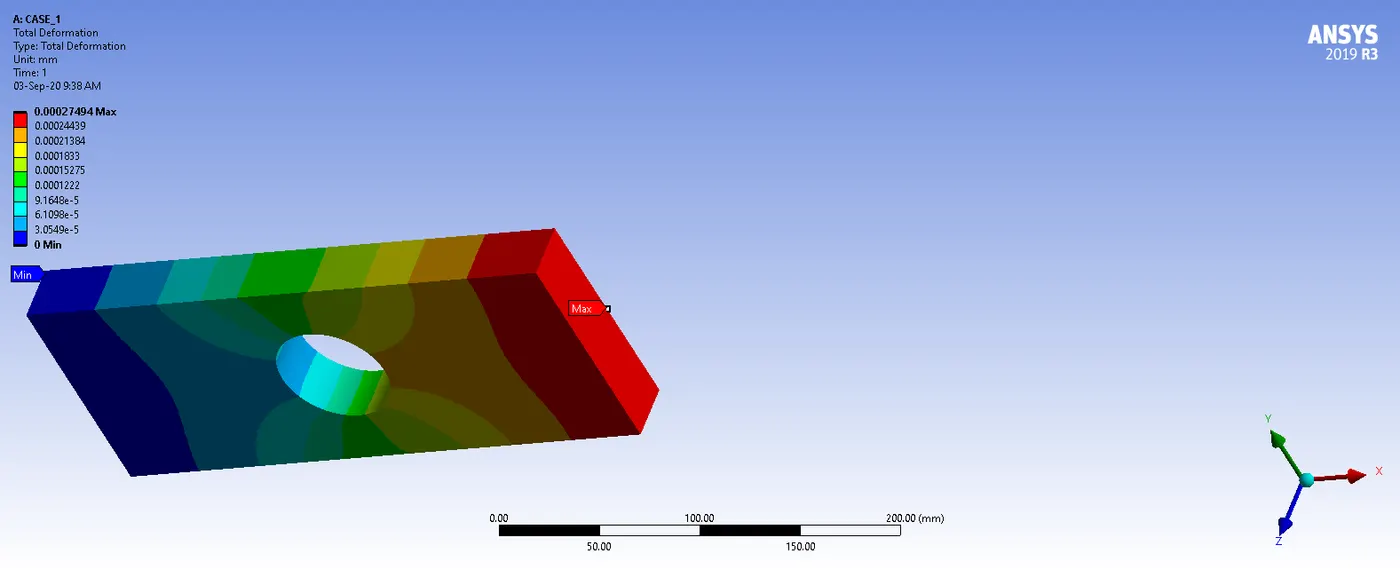
Deformation Contours:
_ _ _ _ _ _ _ _ _ _ _ _ _ _ _ _ _ _ _ _ _ _ _ _ _ _ _ _ _ _ _ _ _ _ _ _ _ _ _ _ _ _ _ _ _ _ _ _ _ _ _ _ _ _ _ _ _ _ _
CASE_2
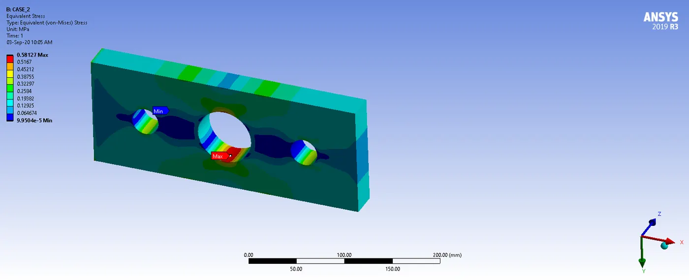
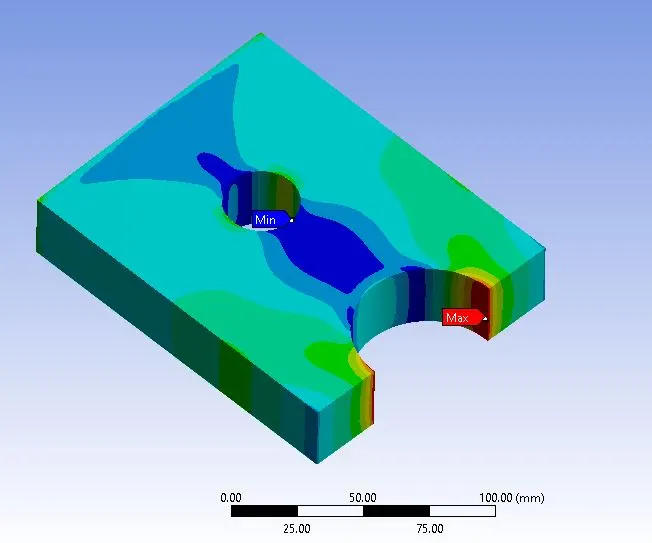
Stress Contours:
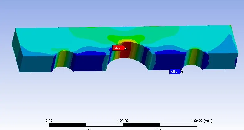
Stress Contours at sections:
Deformation Contours:
________________________________________________________________________________________________________________________
Comparison:

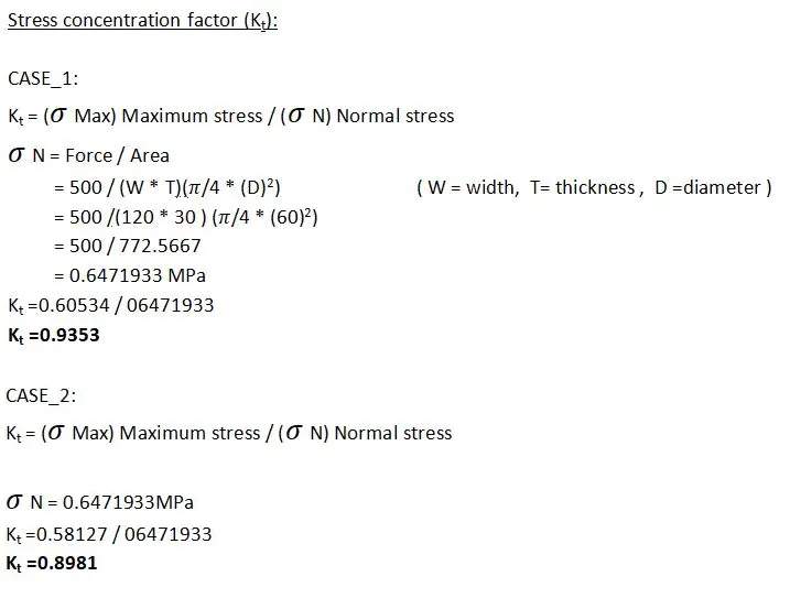
- We can see that Stress concentration factor at the centre hole is less in CASE_2 then CASE_1.
- Less Stress concentration factor in CASE_2 is due to stress distribution due to another two holes.
- Also Maximum stress found in CASE_2 is less due to stress distribution.
______________________________________________________________________________________________________________________________________
Conclusion:
- In CASE_1, due to hole at the centre, there is maximum stress generating at the hole area.
- In CASE_2, we added two small holes. Due to that, stress has been distributed along the plate. So in CASE_2, there is less stress.
- So we can get less stress with stress distribution.
- From an Analysis Standpoint, we should select Plate with three holes as in CASE_2.
Because, it creates less stress, less stress concentration factor and have more life then plate with one hole.
- From a Manufacturing Standpoint, we should select plate with single hole at centre.
Because there is less operation due to only one hole. So less material removal process and wastage of material.
It will also cost low due to less work and effort.
________________________________________________________________________________________________________________________
NOTE: Links for the video animations for CASE_1 & CASE_2 are as given below:
CASE_1
STRESS: https://drive.google.com/file/d/1dYOLqeAQ3a33cmMb9II5wSnKXhg5qqa3/view?usp=sharing
DEFORMATION:https://drive.google.com/file/d/1Z2icZOrzHd3k5k8b7cfaWrcxB8m6WsyD/view?usp=sharing
CASE_2
STRESS: https://drive.google.com/file/d/16GUN7yUZspWmdnBJDdJMA45q2wB7sm9t/view?usp=sharing
DEFORMATION: https://drive.google.com/file/d/1hKb916l3zdF_ynA4n9xMVH2q4ZOjnzX6/view?usp=sharing
Also link for the Report in Ducument and Pdf version given as below
DOC: https://drive.google.com/file/d/11g1O3fPVZSpc07a-ulv8rTvCRX20WCXn/view?usp=sharing
PDF:https://drive.google.com/file/d/18nqaoLLCwMuJwTexi4SLAnUqFPoqsLow/view?usp=sharing
_ _ _ _ _ _ _ _ _ _ _ _ _ _ _ _ _ _ _ _ _ _ _ _ _ _ _ _ _ _ _ _ _ _ _ _ _ _ _ _ _ _ _ _ _ _ _ _ _ _ _ _ _ _ _ _ _ _ _ _ _ _ _ _ _ _ _ _ _ _ _ _
Thanks & Regards,
Dharmesh Joshi