Week - 4 - crash box simulation

Introduction
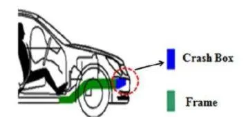
Crash box is used in a vehicle for the purpose of absorbing the crash energy in case of a frontal crash or frontal impact. It is mounted at the front portion of the front rails in a BIW (body in white or structure) of a vehicle. (In the event of impact due to vehicle collision, crash box absorbs impact energy by collapsing so that there is minimum damage to the vehicle parts behind it and also the passengers inside the vehicle are safe. In the event of a crash the crash box should deform prior to other parts by absorbing maximum energy so that there is minimum repair cost after the damage due to crash. Due to need of reduction in weight of vehicle automobile parts are made of thin metal sheets, thus making it more difficult for the crash box to absorb sufficient energy. Hence it is very important to have clear understanding of the effect of material and geometry type on the deformation behavior which can help in achieving the required deformation pattern and energy absorption level. For this purpose, structural crashworthiness studies have been conducted on the behavior of crash box made from GFRP with cylindrical geometry. The effect of triggers (geometrical features or irregularities introduced to achieve the required crash performance) on the performance of the crash box is studied and compared.
____________________________________________________________________________________________________________________________________
Analysis
- Here we will see the Crash Test of Crash box with a Rigid Wall.
- We will see two cases of Crash Box based on its thickness as given below:
CASE_1: Crash Box 1.2 mm
CASE_1: Crash Box 1.5 mm
- Here at the first stage we will take the linear elastic material to verify its correctness. Then we will see two cases of non linear material with 1.2 and 1.5 mm thickness of Crash Box.
- Unit system considered here is gm-mm-ms.
____________________________________________________________________________________________________________________________________
Geometry
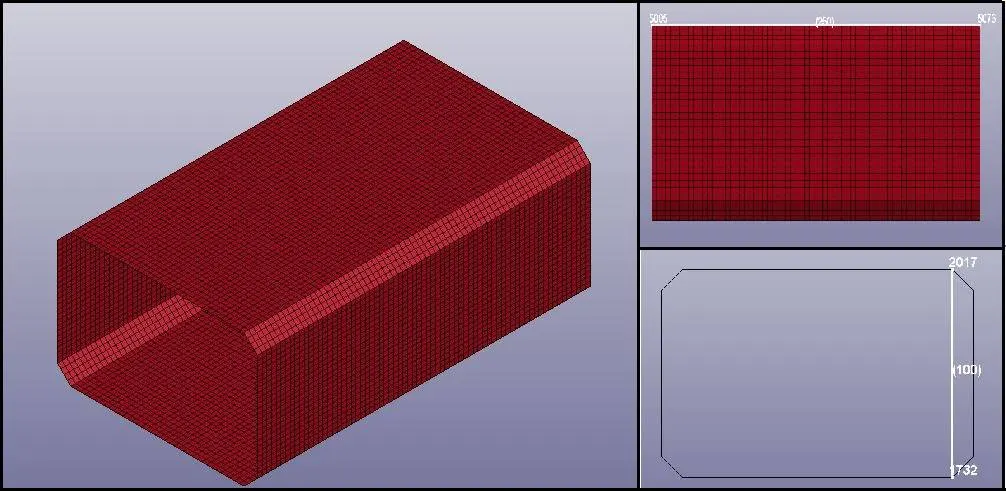
- Simplified geometry of the Crash Box is as given below:
____________________________________________________________________________________________________________________________________
Procedure:
- First of all open the L S DYNA Keyword file named as “new_crash_box.k” in LS-PrePost.
- After importing Crash Box, create appropriate material for Crash Box.
Material:
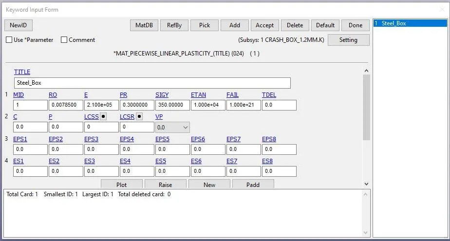
- Create material card for Crash Box as given below.
Material Specifications:
Material Model: PIECEWISE_LINEAR_PLASTICITY (024)
Density: 0.0078500 gm / mm3
Elastic Modulus: 210000 Mpa
Poisson’s Ratio: 0.3
Tensile Yield Strength: 350 Mpa
Section:
- After material card, we have to create two different Section cards as per 1.2 mm and 1.5 mm thickness for CASE_1 & CASE_2 as given below:
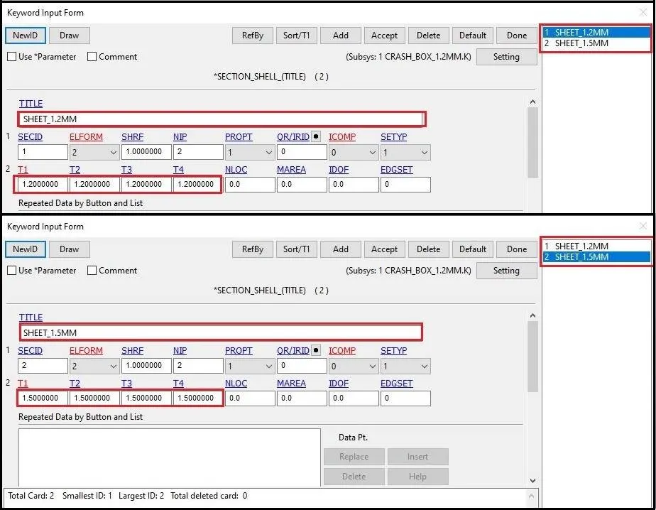
- Here the geometry of Crash Box is made of shell elements, so I have created Section Shell cards.
Part:
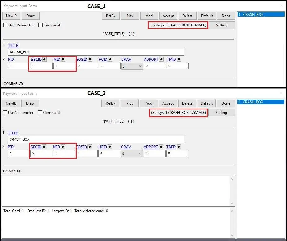
- After creation of Sections and Material, we have to assign it to the Part.
- Also give the Title name to the Par.
- Assign appropriate Material, Section, and Title as per case as given below:
Rigid Wall:
- Here a Rigid Wall is created using “RIGIDWALL_PLANAR” keyword.
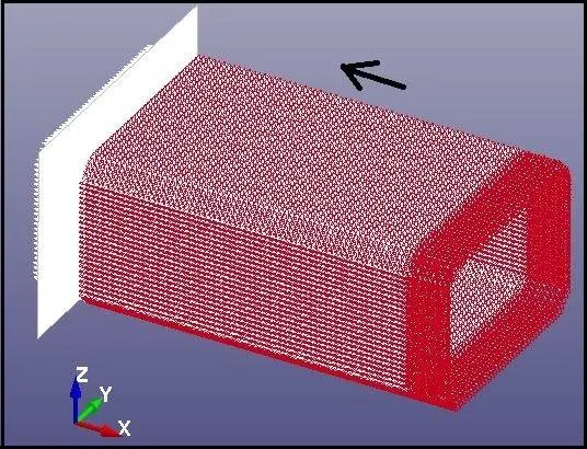
- Rigid Wall is kept at 20 mm distance away from the Crash Box to see the Impact on Crash Box.
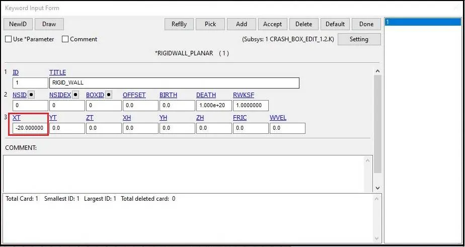
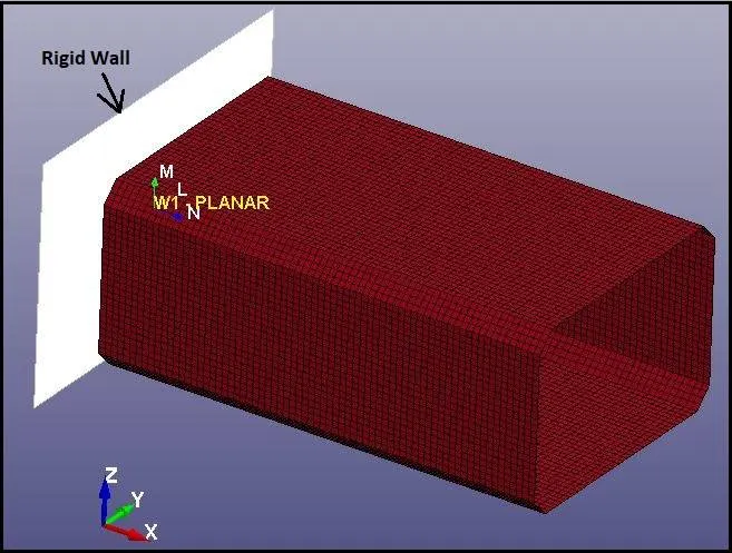
- Here the direction of Rigid Wall Normal is in the opposite direction of the crash.
- This is because we can see the impact and bounce of the crash box from Rigid Wall.
Initial Velocity:
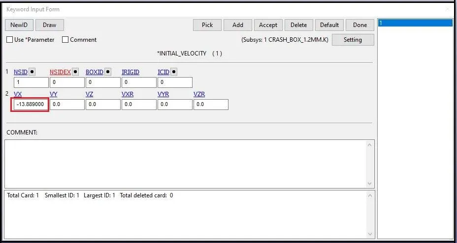
- Assign the initial velocity to Crash Box for crash effect.
- Here Initial Velocity of the Crash Box is around 50 Kmph.
- So (50*1000*1000)/36*100000 = 13.89 mm/ms.
- For crash of the Crash Box with Rigid Wall, Initial velocity should be in the (negative) –X direction.
- So the Initial velocity here will be -13.889 as given below.
Contacts:
- Here Rigid Wall is not deformable.
- So there will be self contact of Crash Box.
- So Contact between Crash Box and Rigid Wall is created using “CONTACT_AUTOMATIC_SINGLE_SURFACE” keyword.
- Since the slave is Crash Box, so no need to define master in this contact.
- Self Contact definition for the interface is given as below:
Contact Single Surface:
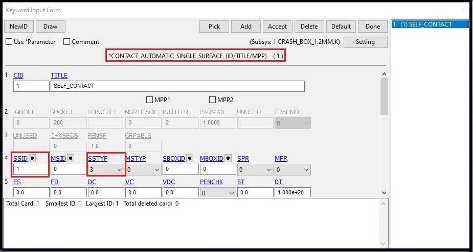
- Automatic single surface contact is created to see the reactions of Crash Box, when it comes in to self contact.
Force Transducer:
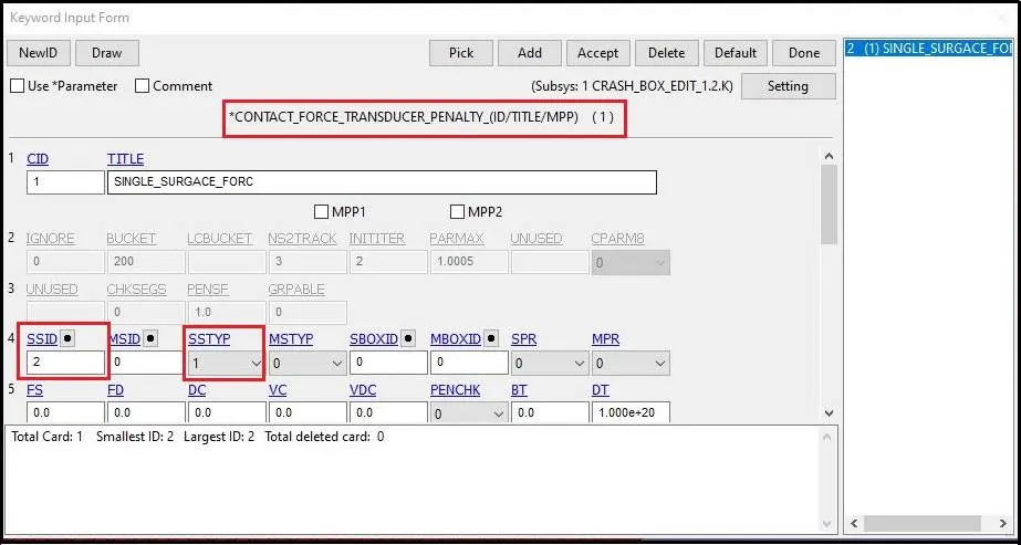
- Also to record contact interface forces “RCFORC”, CONTACT_FORCE_TRANSDUCER_PANELTY” keyword is used.
- This card is similar to the Automatic Single Surface card.
- Here also slave parameters have been assigned in the form of SSID as given below:
Controls:
Energy:
- To get the output for Hourglass energy “CONTROL_ENERGY” keyword is used as given below:
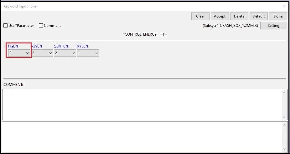
- HGEN =2 is given for computing and including the Hourglass Energy into Energy Balance.
Termination:
- Termination time to end the simulation is defined with “CONTROL_TERMINATION” as given below:
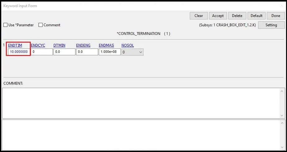
- To see the post crash scenario like bouncing effect of the Crash Box, 10ms is given as a Termination time.
Database:
Binary option:
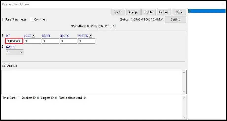
- DATABASE_BINARY_D3PLOT keyword id used for post processing data as well as animations.
- Here 0.1 ms time is given for output update interval.
Ascii option:
- With DATABASE_OPTION keyword, GLSTAT, SLEOUT, RCFORC OUTPUT files has been created for global statistics, sliding interface energies and resultant interface forces respectively.
- Also for the nodal acceleration of the node 6407 at the middle of the Crash Box, is created using NODUOT.
- All ASCII output has been created with 0.1 ms update interval.
cross_section_set:
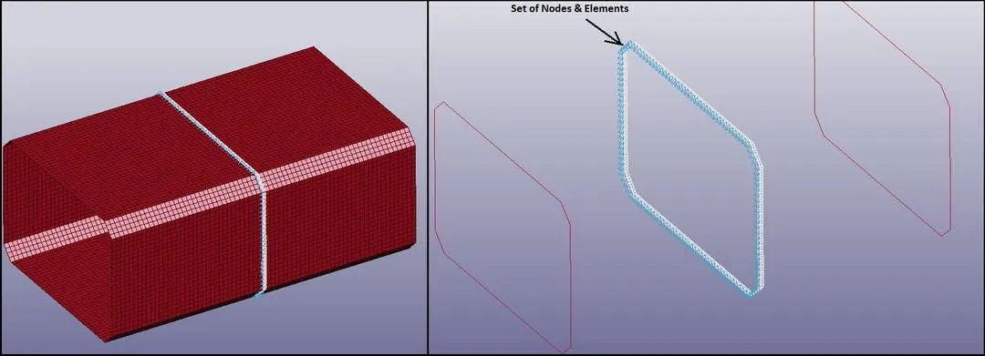
- DATABASE_CROS_SSECTION_SET keyword is used for output of the forces generated at the middle of the cross section of the Crash Box.
- Here for cross section, SET_SHELL_LIST (SSID) as well as NODE_SET_LIST (NSID) is given for the particular set off shell elements and nodes related to those elements as shown in below image.
____________________________________________________________________________________________________________________________________
Results & Discussion:
CASE_1
Stress:
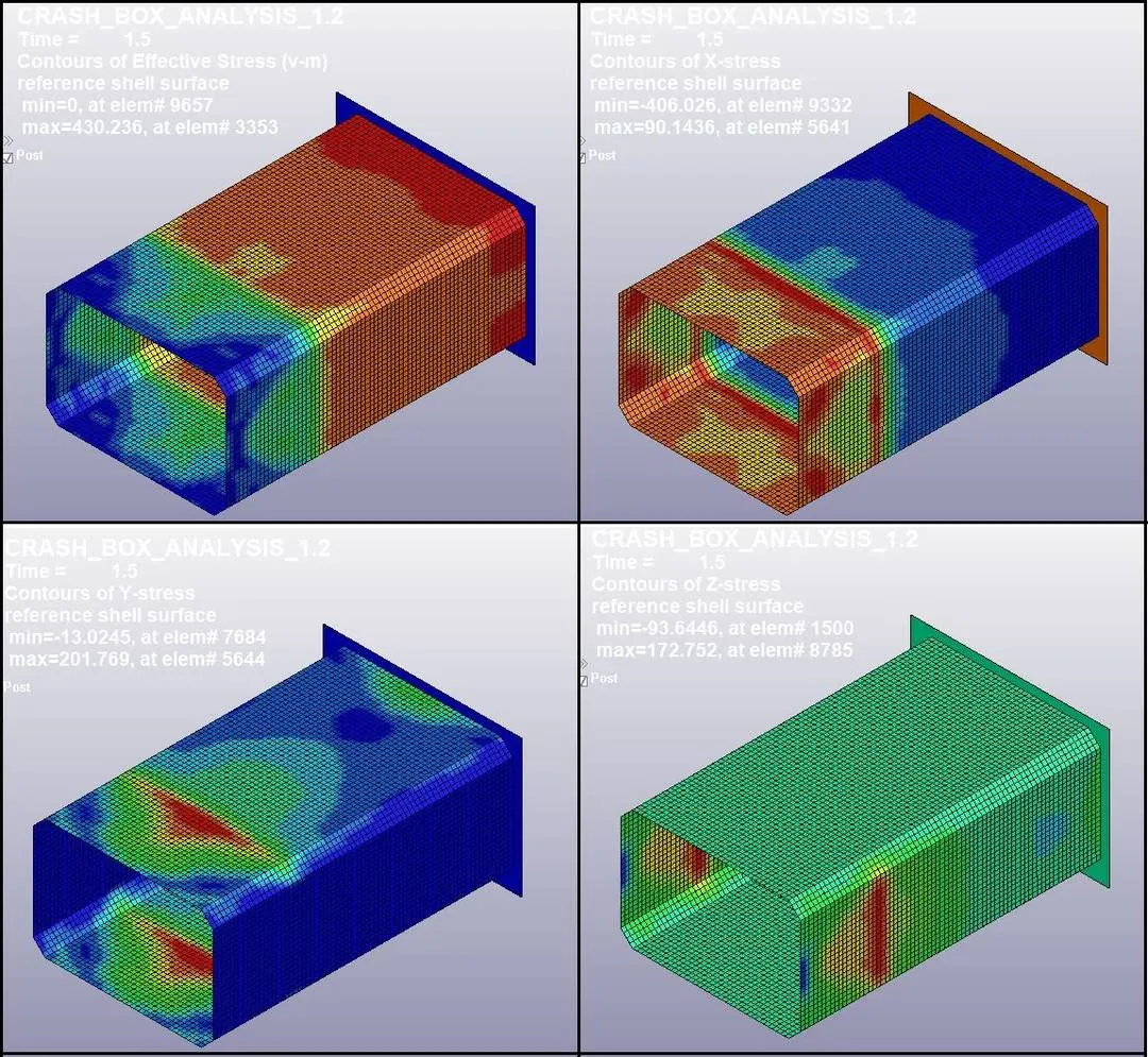
- Here we can see that maximum effective stress is generating at the time of impact is 430.23 Mpa.
- Also we can observe that lateral stress in Y and Z directions are more compared to longitudinal stress in X direction when Crash Box impacts.
- As we know that Yield strength of the Steel material for Crash Box is 350 Mpa. As maximum stress generation is 430 Mpa, so we can say that there can be some plastic deformation in the Crash Box.
Strain:
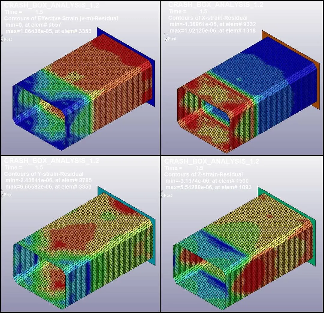
- Here we can see the permanent/ residual strain.
- Maximum residual strain due to plastic deformation is 1.86436 e-5, which is very low.
- But residual strain in Y and Z direction is higher than in X direction.
Global Energies:
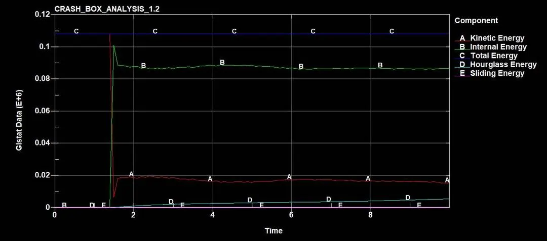
- Here we can observer sudden decrease in kinetic energy due to crash. Also there is a sudden increase in internal energy at the time of impact at 1.5 ms.
- Sliding energy is near to zero because here the rigid wall is not deformable.
- Also Hourglass energy is within the 10% of the internal energy, which is good.
Cross section forces at middle of Crash Box:
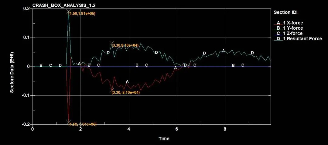
- Maximum force at the middle cross section of Crash Box is 191 KN.
Nodal Acceleration (Node ID: 6407):
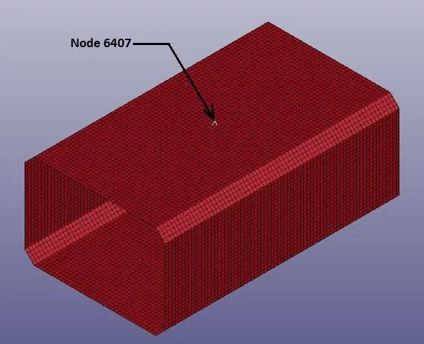
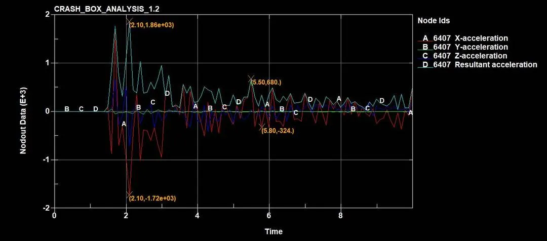
- As shown in above image, nodal acceleration of the node 6707 at the middle cross section is 1.86 e+3 mm/ms2.
RCFORC:

- Here Resultant Interface forces observed are zero. It is because the rigid wall is not deformable.
_ _ _ _ _ _ _ _ _ _ _ _ _ _ _ _ _ _ _ _ _ _ _ _ _ _ _ _ _ _ _ _ _ _ _ _ _ _ _ _ _ _ _ _ _ _ _ _ _ _ _ _ _ _ _ _ _ _ _ _ __ _ _ _ _ _ _ _ _ _ _ _ _ _ _ _ _ _ _ _ _ _ _ _
CASE_2
Stress:
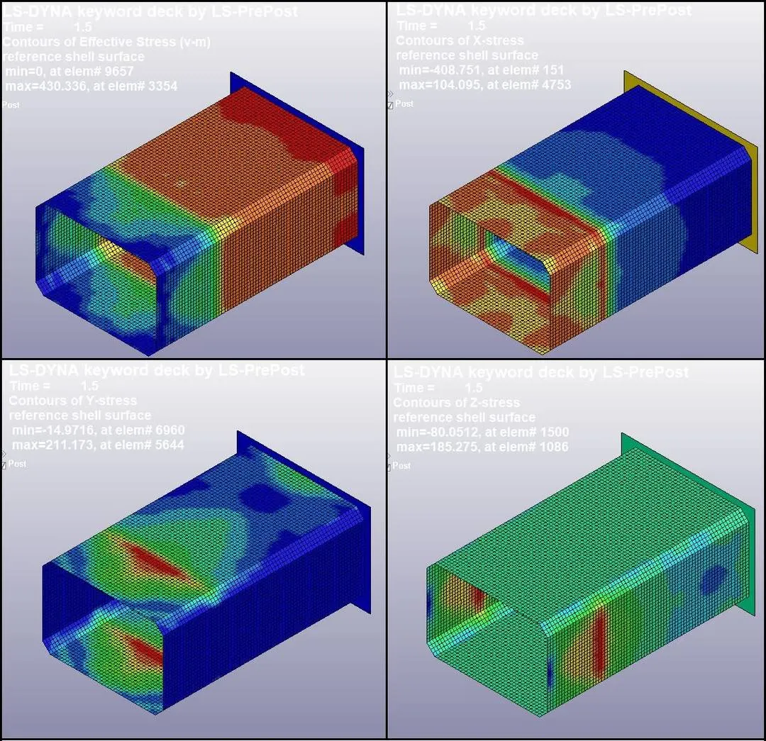
- Here we can see that maximum effective stress is generating at the time of impact is 430.336 Mpa.
- Also we can observe that lateral stress in Y and Z directions are more compared to longitudinal stress in X direction when Crash Box impacts.
- As we know that Yield strength of the Steel material for Crash Box is 350 Mpa. As maximum stress generation is 430 Mpa, so we can say that there can be some plastic deformation in the Crash Box.
Strain:
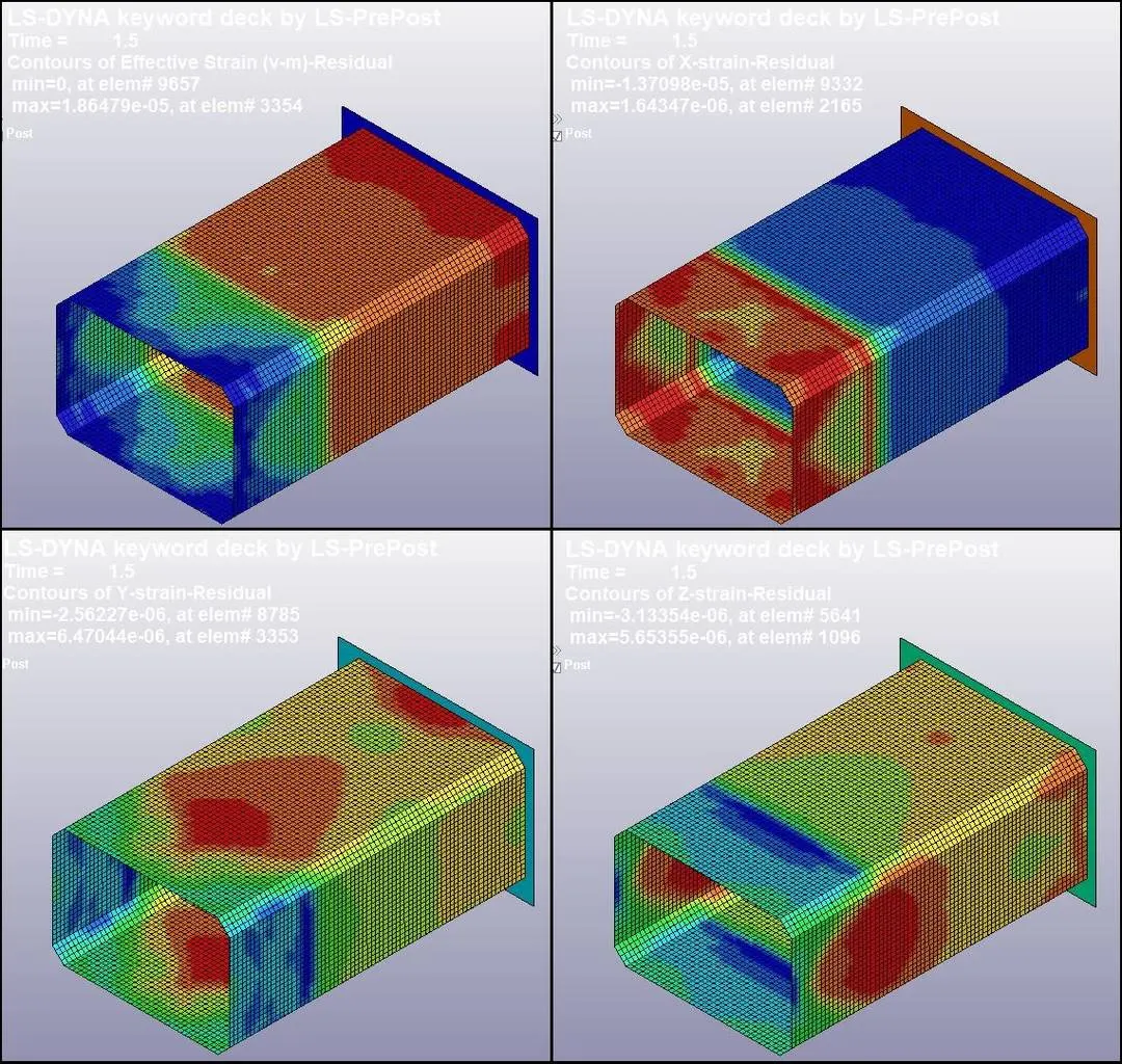
- Here we can see the permanent/ residual strain.
- Maximum residual strain due to plastic deformation is 1.86479 e-6, which is very low.
- But residual strain in Y and Z direction is higher than in X direction.
Global Energies:
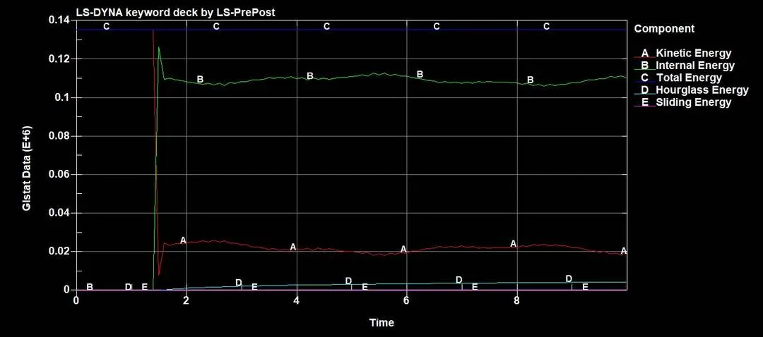
- Here we can observer sudden decrease in kinetic energy due to crash. Also there is a sudden increase in internal energy at the time of impact at 1.5 ms as in CASE_1.
- Sliding energy is near to zero because here the rigid wall is not deformable.
- Also Hourglass energy is within the 10% of the internal energy, which is good.
Cross section forces at middle of Crash Box:
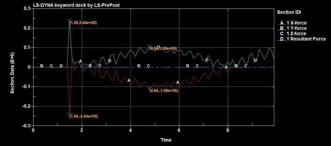
- Maximum force at the middle cross section of Crash Box is 240 KN.
Nodal Acceleration (Node ID: 6407):
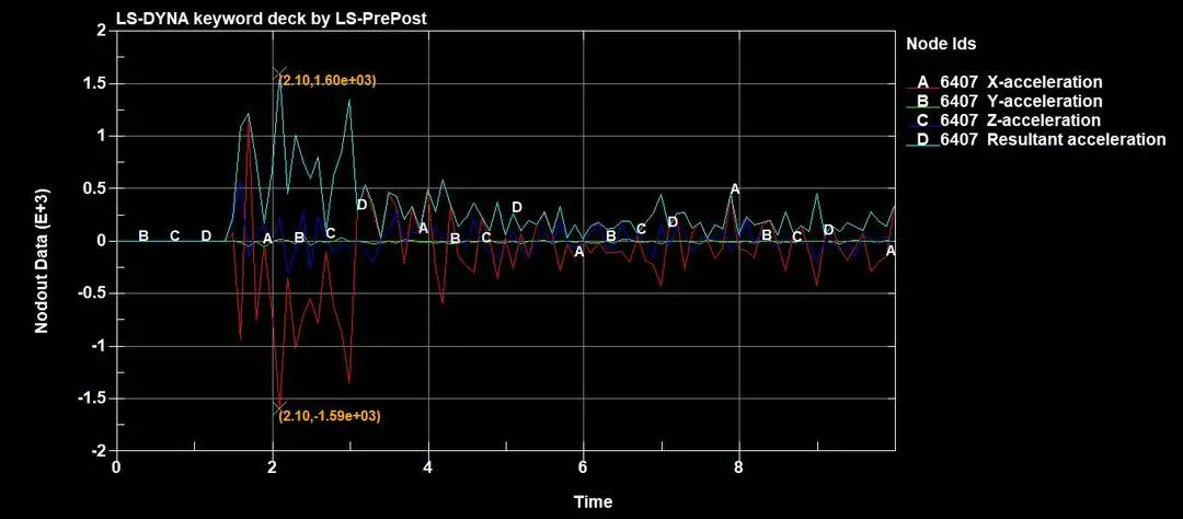
- As shown in above image, nodal acceleration of the node 6707 at the middle cross section is 1.60 e+3 mm/ms2.
RCFORC:
- As in CASE_1, Resultant interface forces will be zero because here the Rigid Wall is not deformable.
____________________________________________________________________________________________________________________________________
Comparison:
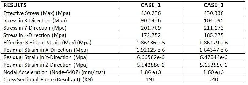
- From above tabular data, we compare that, Stress in CASE_2 are higher in all direction compared to CASE_1.
- Also due to increased thickness and stress, strains value for CASE_2 is also higher.
- But due to increased thickness, Crash Box in CASE_2 is less flexible than CASE_1, so we can observe less acceleration of the node at the middle of the Cross Box.
- Also with increases thickness, higher sectional forces at the middle portion of the Crash Box can be noticed.
____________________________________________________________________________________________________________________________________
Conclusion:
- We can conclude that with proper thickness of the Crash Box, we can achieve better results for crash.
- As we know that purpose of the Crash Box is to prevent the structure attached to it. And for that, we should use proper materials and required thickness, in a way that it can withstand the jerks.
- Crash Box should be enough flexible that it can absorb the maximum forces and minimize the damage of entire structure.
- Here in these two cases we can observe the increases stresses and strains due to higher thickness value.
- We can see the bouncing effect of the Crash Box when it crashes, which is good for minimum damage from the crash.
______________________________________________________________________________________________________________________
Animations:
CASE_1:
Stress:

Residual Strain:
_ _ _ _ _ _ _ _ _ _ _ _ _ _ _ _ _ _ _ _ _ _ _ _ _ _ _ _ _ _ _ _ _ _ _ _ _ _ _ _ _ _ _ _ _ _ _ _ _ _ _ _ _ _ _ _ _ _ _ _ _ _ _ _ _ _ _ _ _ _ _ _ _ _ _ _ _ _ _ _ _
CASE_2
Stress:
Residual Strain:
______________________________________________________________________________________________________________________
Thanks & Regards,
Dharmesh Joshi