Week 4 -Wire Bending Challenge

Introduction
Although there are many types of wire forming, in production wire forming specialized machinery is used. These wire 4-Slide Wire forming machines have many methods that can be employed to achieve the desired results however only a few are available to manufacture repeatable and fast results. In years past this was achieved through the use of machinery using CAM’s to actuate benders (old technology). These CAM operated 4-Slide machines required extensive setup, many trial runs and scrapped parts and large quantities to make it all that setup worthwhile. Today, using CNC technology, the new and highly modifiable machines form wire for hundreds of processes from rebar used in concrete forms to store racks & shopping carts along with millions of other parts in between even including jewelry. Although this manufacturing technology has been around for thousands of years it has become a very specialized and highly technical industry.
Wire Forming:
Wire Forming is the process of taking a blank of wire whether from a spooled coil or blank length and forming or bending it into a specific configuration. This can be achieved either by a manual method of brute force applied to bending the wire around controlled shapes and utilizing machinery to feed and manipulate the wire to the desired shape. Wire forming can also include flattening and forming of the wires roundness as well in order to allow for proper fit for use of the product being designed.
______________________________________________________________________________________________________________________________________
Analysis:
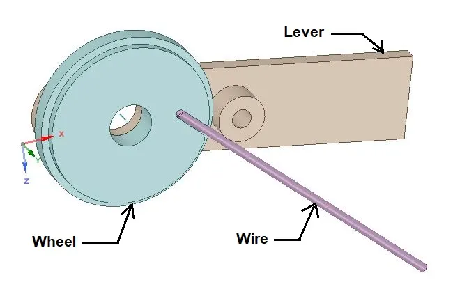
Here we will see the Wire bending process by simple mechanism of Wheel and Lever.
We are concerned about the effect on different Nonlinear material of Wire on Wire bending process.
- Cases for different Wire material used in Wire bending process are as described below:
CASE_1: Copper_Alloy_NL
CASE_2: Aluminium_Alloy_NL
CASE_2: Magnesium_Alloy_NL
______________________________________________________________________________________________________________________________________
Geometry:
________________________________________________________________________________________________________________________
Material:
- Material Specifications for CASE_1:
Copper Alloy NL
Density: 8300 Kg/m3
Young’s Modulus: 1.1 E+05 MPa
Poisson’s Ratio: 0.34
Yield Strength: 280 MPa
Tangent Modulus: 1150 Mpa
- Material Specifications for CASE_2:
Aluminium Alloy NL
Density: 2770 Kg/m3
Young’s Modulus: 71000 MPa
Poisson’s Ratio: 0.33
Yield Strength: 280 MPa
Tangent Modulus: 500 Mpa
- Material Specifications for CASE_3:
Magnesium Alloy NL
Density: 1800 Kg/m3
Young’s Modulus: 45000 MPa
Poisson’s Ratio: 0.35
Yield Strength: 193 MPa
Tangent Modulus: 920 Mpa
________________________________________________________________________________________________________________________
Mesh:
Details:
- Global Element Size: Default
- Quality: > Smoothing: Low
- Patch Conforming Method: Tetrahedrons
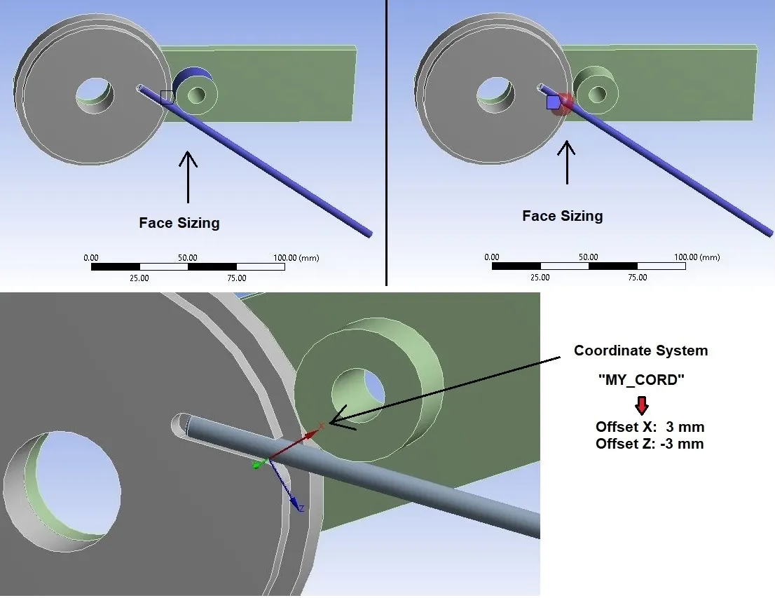
- Face Sizing : All Faces in Contact (4 Faces)
Element Size = 2.2 mm
- Face Sizing : Wire Face (1 face)
Type: Sphere of Influence
Sphere Center: “MY_CORD”
Sphere Radius: 7 mm
Element Size: 0.8 mm
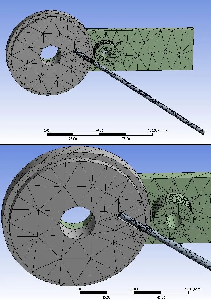
- No. of Nodes: 8145
- No. of Elements: 4090
________________________________________________________________________________________________________________________
Procedure:
- Import model in Static Structural named as “Skill_Lync_Wire bending model.x_t” in Geometry section.
- Then go to Mechanical model section.
- Check or Rename the Parts of the setup as “Wheel”, “Wire” and “Lever” as shown in above geometry image.
Connections:
- Delete automatically created contacts and create new contacts as given below:
Contact_1:
Contact Body = Wire
Target Body = Lever
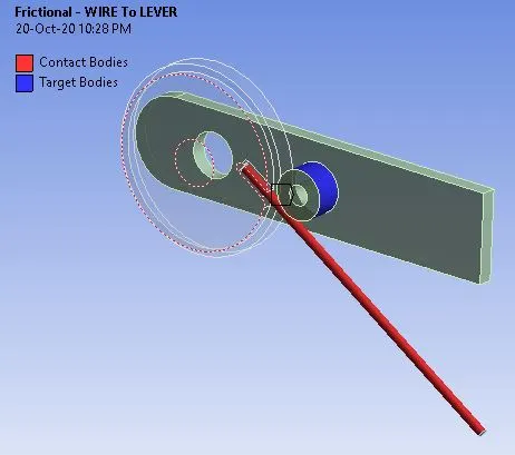
Contact_2:
Contact Body = Wheel
Target Body = Wire
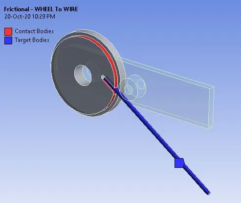
Settings for both Contacts:
- Type: Frictional
- Friction Coefficient: 0.2
- Formulation: Augmented Lagrange
- Normal Stiffness : By factor
- Normal Stiffness Factor: 0.1
- Update Stiffness: Each Iteration
- Interface Treatment: Add Offset, Ramped Effects
Joints:
Joint_1
Connection Type: Body-Ground
Type: Revolute
Body: Lever
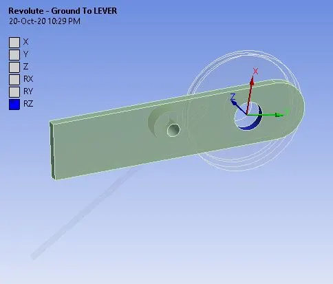
> Make sure that coordinate system for the Revolute Joint has been set as shown in above image.
Boundary Conditions:
- After meshing as described above, create Boundary Conditions as given below:
Analysis Settings:
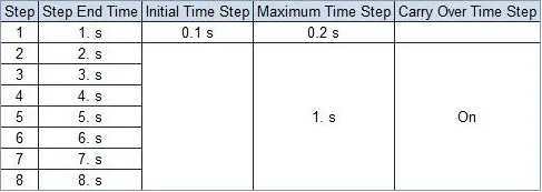
- No. of Steps: 8
For 1st Step:
- Solver Type: Direct
- Large Deflection: ON
- Auto Time Stepping: ON
- Defined By : Time
- Initial Time Step: 1 s
- Minimum Time Step: 0.01 s
- Maximum Time Step: 0.2 s
- Output Controls: “All Yes”
For 2nd to 8th t Step:
- Solver Type: Direct
- Large Deflection: ON
- Auto Time Stepping: ON
- Defined By : Time
- Carry Over Time Step: ON
- Minimum Time Step: 0.01 s
- Maximum Time Step: 1 s
- Output Controls: “All Yes”.
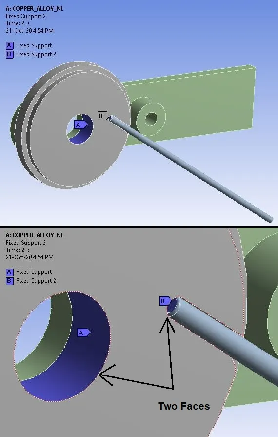
Fixed Support:
- Apply Fixed Support for fixing the movement of Wheel and Wire from its location as given below:
Solution:
- After giving proper boundary conditions, create desired solutions for output results.
- Create Solutions for :
- Equivalent Stress For Wire
- Equivalent Strain for Wire
- Total Deformation for Wire
________________________________________________________________________________________________________________________
Results:
- Now we will see all results with comparison.
Comparison of CASE_1, CASE_2 AND CASE_3:
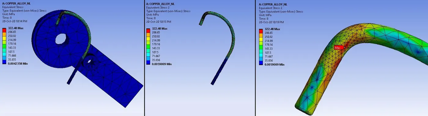
Stress Contours for Copper Alloy NL:
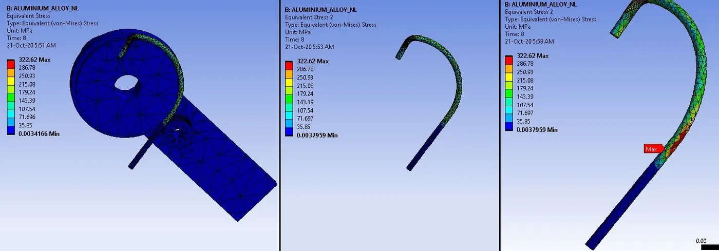
Stress Contours for Aluminium Alloy NL:
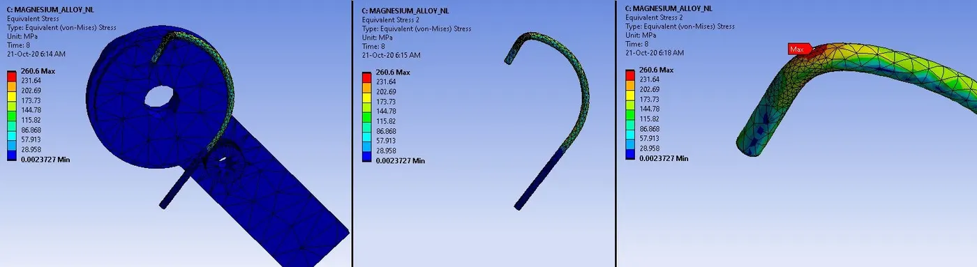
Stress Contours for Magnesium Alloy NL:
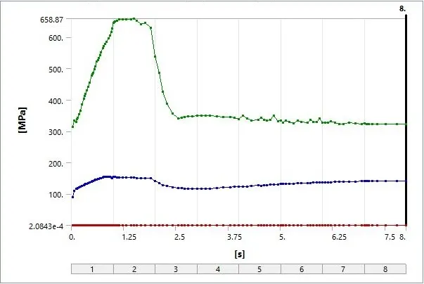
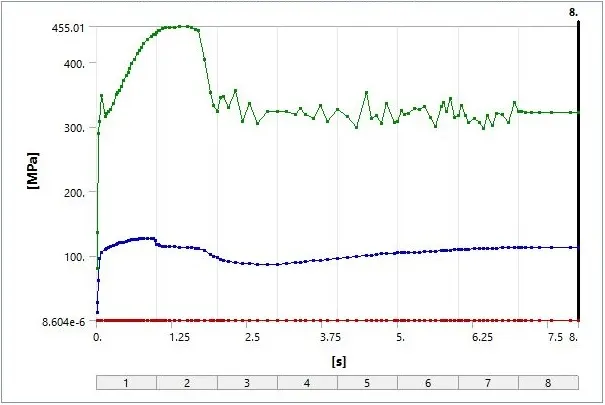
Stress Plot for Copper Alloy NL:
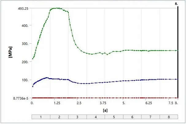
Stress Plot for Aluminium Alloy NL:
Stress Plot for Magnesium Alloy NL:
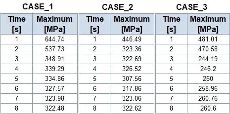
Stress Data for Copper Alloy NL, Aluminium Alloy NL, and Magnesium Alloy NL:
_ _ _ _ _ _ _ _ _ _ _ _ _ _ _ _ _ _ _ _ _ _ _ _ ___ _ _ _ _ _ _ _ _ _ _ _ _ _ _ _ _ _ _ _ _ _ _ _ _ _ _ _ _ _ _ _ _ _ _ _ _ _ _ _ _ __ _ _ _ _ _ _ _ _ _ _ _
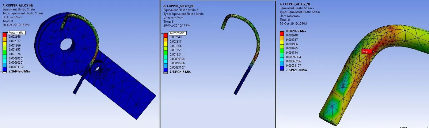
Strain Contours for Copper Alloy NL:
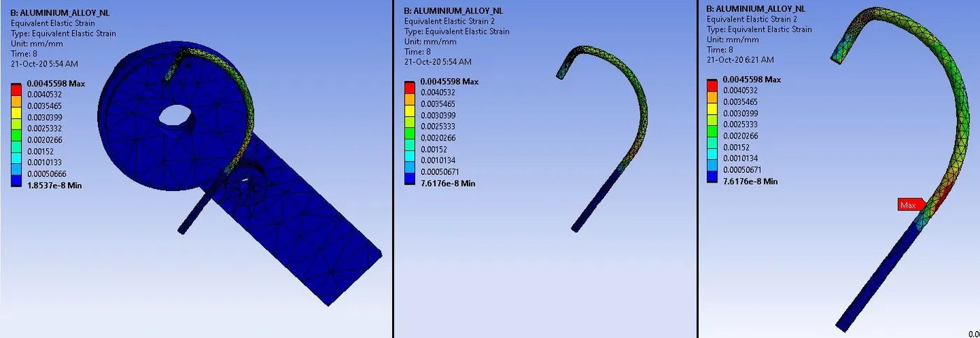
Strain Contours for Aluminium Alloy NL:
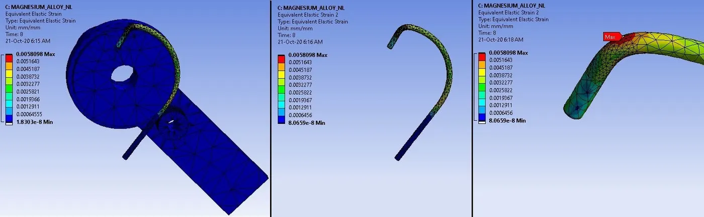
Strain Contours for Magnesium Alloy NL:
Strain Plot for Copper Alloy NL:
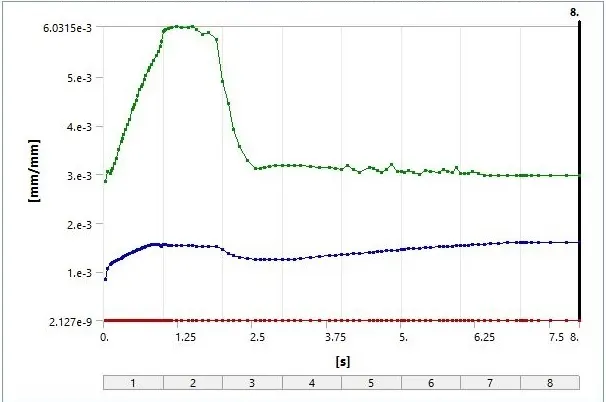
Strain Plot for Aluminium Alloy NL:
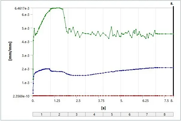
Strain Plot for Magnesium Alloy NL:
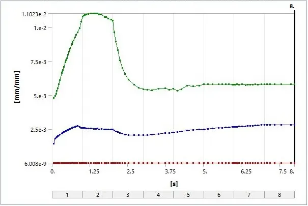
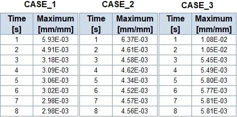
Strain Data for Copper Alloy NL, Aluminium Alloy NL, and Magnesium Alloy NL:
_ _ _ _ _ _ _ _ _ _ _ _ _ _ _ _ _ _ _ _ _ _ _ _ ___ _ _ _ _ _ _ _ _ _ _ _ _ _ _ _ _ _ _ _ _ _ _ _ _ _ _ _ _ _ _ _ _ _ _ _ _ _ _ _ _ __ _ _ _ _ _ _ _ _ _ _ _
Deformation Contours for Copper Alloy NL:
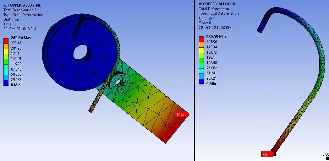
Deformation Contours for Aluminium Alloy NL:
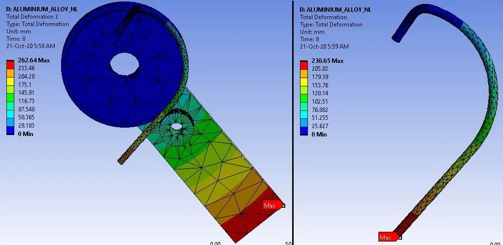
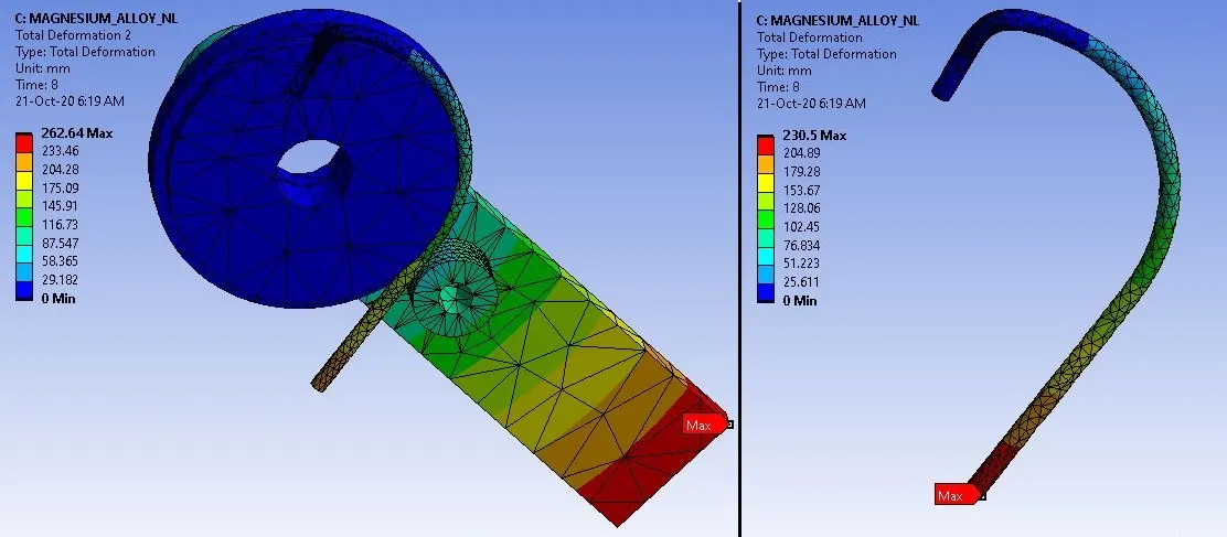
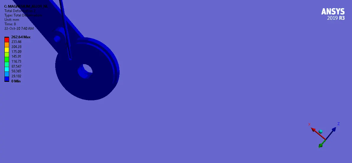
Deformation Contours for Magnesium Alloy NL:
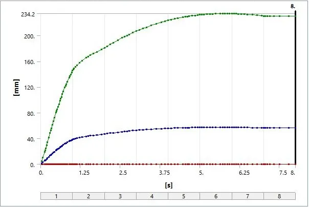
Deformation Plot for Copper Alloy NL:
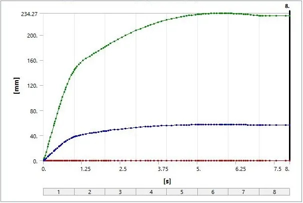
Deformation Plot for Aluminium Alloy NL:
Deformation Plot for Magnesium Alloy NL:
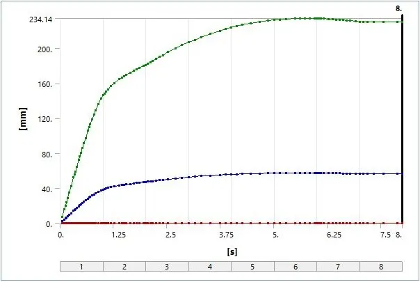
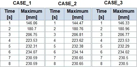
Deformation Data for Copper Alloy NL, Aluminium Alloy NL, and Magnesium Alloy NL:
_ _ _ _ _ _ _ _ _ _ _ _ _ _ _ _ _ _ _ _ _ _ _ _ ___ _ _ _ _ _ _ _ _ _ _ _ _ _ _ _ _ _ _ _ _ _ _ _ _ _ _ _ _ _ _ _ _ _ _ _ _ _ _ _ _ __ _ _ _ _ _ _ _ _ _ _ _
- As per above comparisons, we can see that Copper Alloy NL faces high stress compare to other material. So it is stiffer than two other materials and can be hard for bending.
- We can observe that in case of Copper Alloy and Magnesium Alloy, stress and strain developes maximum at the contact region but in case of Aluminium Alloy, it is lower portion. So Aluminium Alloy does not behave properly and can lead to spring back effect.
- We can observe that Magnesium Alloy NL material has higher strains. Because of low Yield Strength, it is will deform early and easy for bending.
________________________________________________________________________________________________________________________
Conclusion
- Stiffness is the resistance of a wire to tension or bending. Wires with low stiffness have high elasticity, and their slope is close to horizontal. They can be bent easily, and they return to their original position when the stress is removed.
- Also Formability is important factor which shows the area between breaking point and plastic deformation for material.
- It terms of bending process, we can see from the results that Magnesium Alloy NL can be bent very easily. It does not need high load for bending.
- Application of wire determines which the material should be used for bending. In electric components, we can see that Copper material is used due to their supper elasticity. But in case where conductivity is not important, we can use Magnesium Alloys for their easy bending process.
- Stiffness is very important factor in Wire bending process. Stiffness or load/deflection rates of wires are affected by three factors: size, length, and material. To change the stiffness of a wire, one, two, or all three of these factors must be considered.
________________________________________________________________________________________________________________________
References
- https://en.wikipedia.org/wiki/Wire_drawing
- https://courses.lumenlearning.com/physics/chapter/5-3-elasticity-stress-and-strain/
- https://www.slideshare.net/shabeelpn/wire-bending-principles
- https://www.sciencedirect.com/topics/engineering/ground-wire
- https://pocketdentistry.com/application-of-orthodontic-force/
________________________________________________________________________________________________________________________
Animations:
Stress:

Strain:

Deformation:
___________________________________________________________________________________________________________
Thanks & Regards,
Dharmesh Joshi
__________________________________________________________________________________________________________
NOTE: Due to large size of Ansys File, it is given by the link in Document. See the Document given in the Model Browse.