Week - 5 - Modelling Spotwelds
Aim :
To model spotwelds for the given assembly of parts and run a crash test .
Solution :
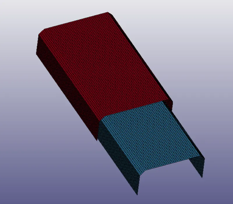
We have the following crash box as shown :
Creation of spotwelds using beam elements :
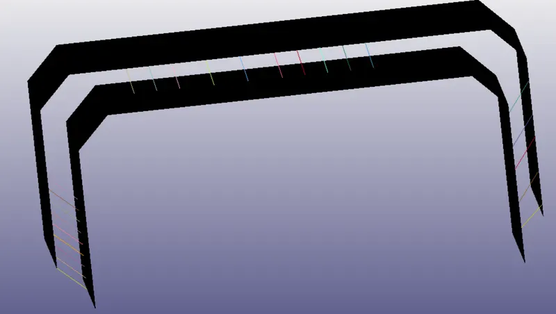
We will create spot welds using beam elements as shown below :
Assigning material to spotweld :
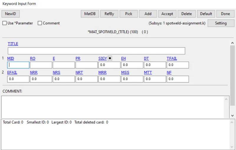
We are using mat 100 spotweld to define the material of the spotweld as shown below :
Assigning Spotweld section :
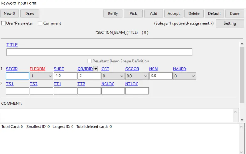
We will element formulation as 9 as it is made spot weld only .
We will define a rigid wall as shown below :
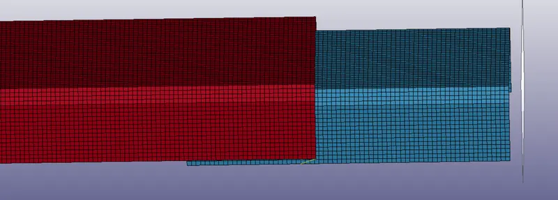
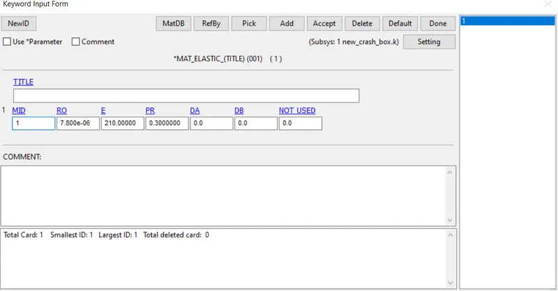
Now we will assign material to the main part as shown in the above picture :
Now we will define the contact for the spotweld as shown below :
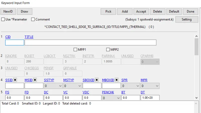
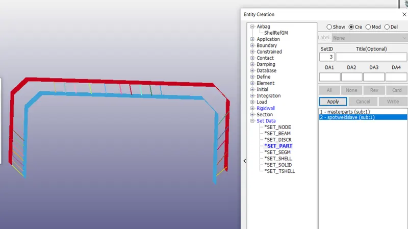
In this we have to make sure that all the parts which are being connected via the spotweld are in a single part set which can be used as the master and all the spotwelds should be in a single part set that will be used as the slave as shown below :
We will also create the self contact as shown :
Now we will add output file and talk about the following keywords
1.Nodeout
This an output data found in ascii where it is used to output the force etc at particular node .
2.Swforce
This is used to output the data of forces etc acting at an spotweld
3.Database History node
This is used to select the nodes at which output is required .
There is an alternative way to create spotweld as shown below :
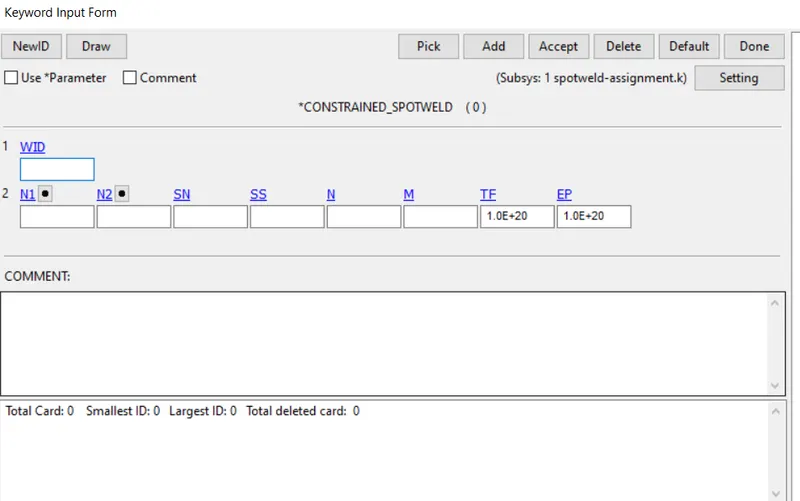
The issue of beam element is that it can take force acting in only one direction , hence we have to use solid elements.
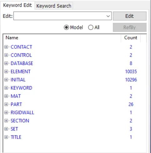
We have added the basic keycards as shown below :
Now we discuss the results of the crash simulation as shown below :
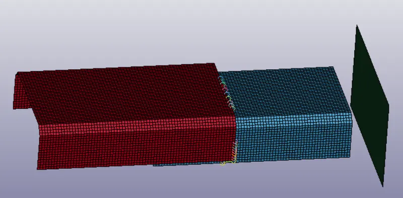
We get :
Results :
Energy :
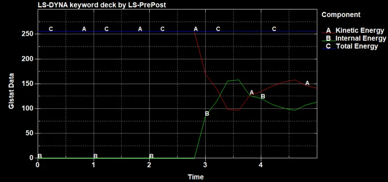
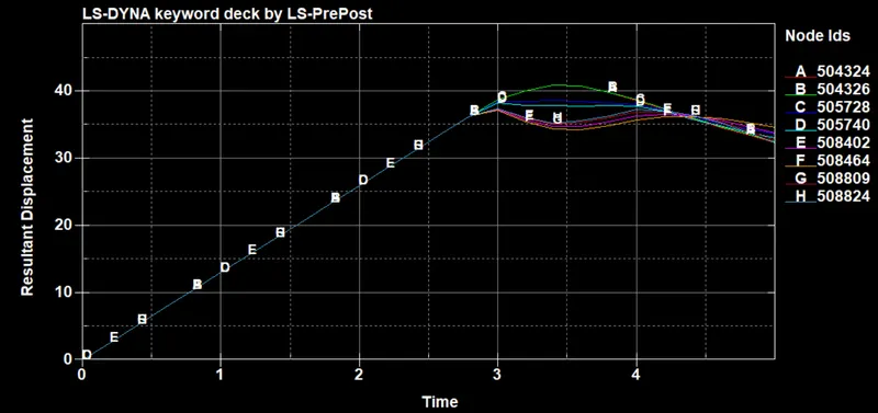
The total displacements at the nodes is :
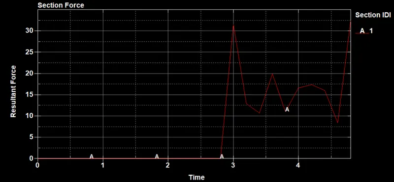
Now we will display the sectional force :
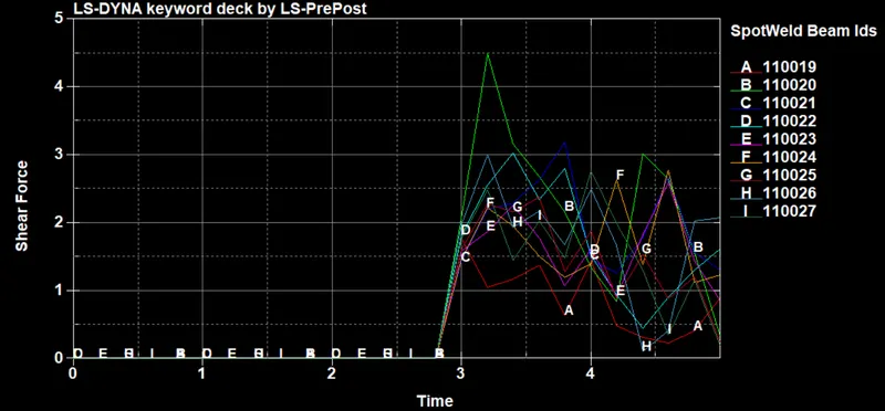
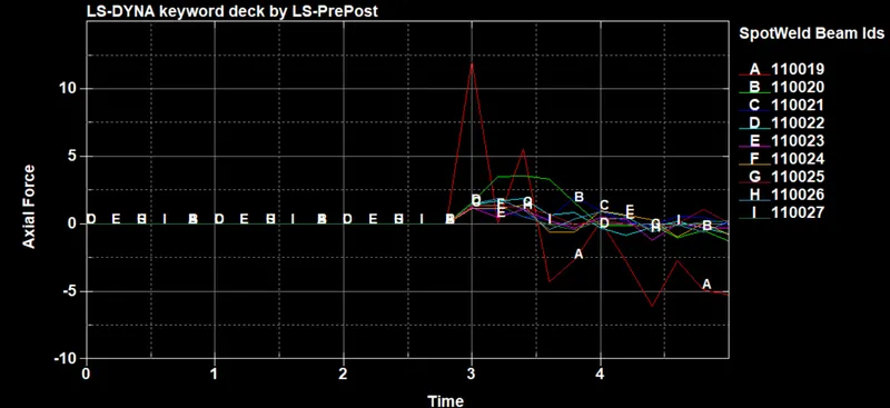
The forces at the spotweld as shown :
Case 2 : Spot Weld using Solid Elements
We have the following :
Results :
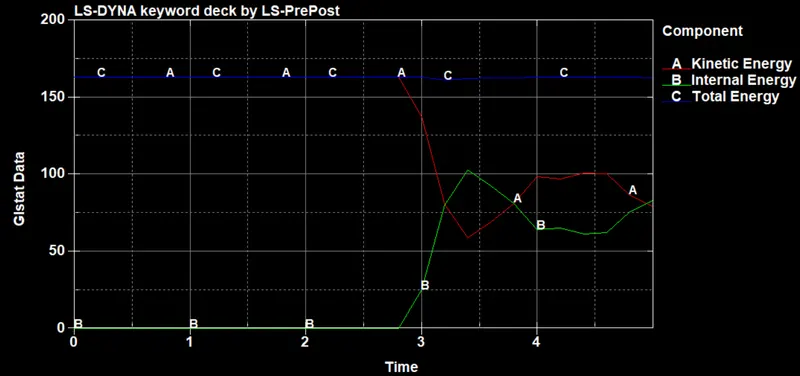
Energy :
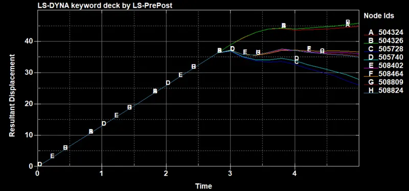
The total displacements at the nodes is :
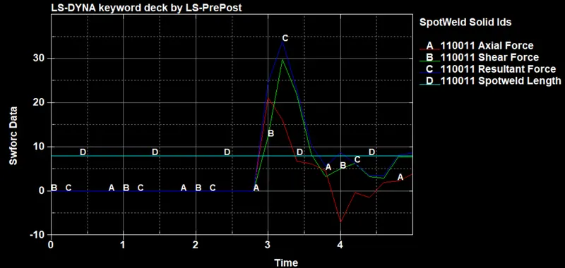
The forces at the spotweld as shown :
Conclusion
Therefore simulation using different kinds of spotwelds was performed and a comparsion was done.