Week - 4 - Crash Box Simulation
Aim :
In this assignment, the student needs to simulate a crash test for a crash box for which mesh is given. A crash box is a highly energy absorbing structure that crashes on application of loads and reduces impact on other components nearby. A full-fledges crashbox is a highly sophisticated design but in this case we will go with a rectuangular channel which can thought of as the most simple crashbox.
Here are the different assumptions and information required:
- The crashbox should crash into a rigidwall created using *RIGIDWALL_ keyword. Check the manual to understand and create a rigidwall.
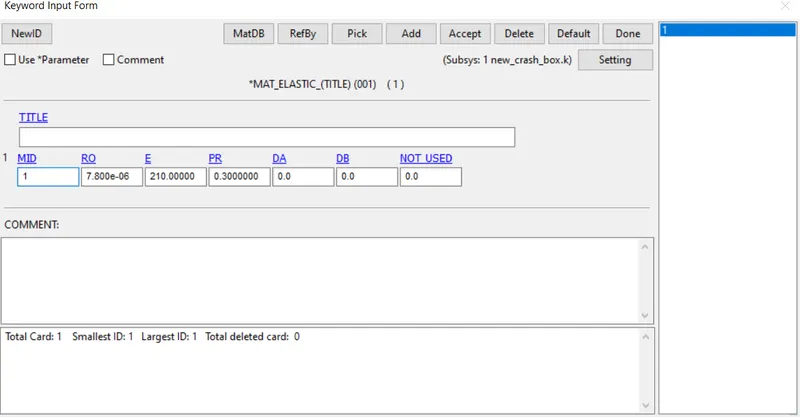
- Material for the crashbox is steel. The simulation needs to be started using elastic material to verify its correctness and later a nonlinear material card data will be provided. Thickness of the crashbox is 1.2mm.
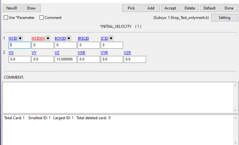
- Initial velocity for the crashbox should be around 50 kmph
- The units system to be used is gm-mm-ms
- The simulation should satisfy either of the two situations - (1) It crashes on the rigidwall and rebounces completely or (2) it buckles and folds in the axial direction so as to come in self-contact.
- Once the simulation is completed and results as asked for below is collected, run another simulation by increasing the thickness of the crashbox from 1.2 to 1.5mm.
Solution :
First we will talk about a few basic terms related to simulation such as :
1.Boundary Conditions :
Boundary conditions (b.c.) are constraints necessary for the solution of a boundary value problem. A boundary value problem is a differential equation (or system of differential equations) to be solved in a domain on whose boundary a set of conditions is known. It is opposed to the “initial value problem”, in which only the conditions on one extreme of the interval are known. Boundary value problems are extremely important as they model a vast amount of phenomena and applications, from solid mechanics to heat transfer, from fluid mechanics to acoustic diffusion.
We will discuss the cards used to describe boundary condition as shown:
1.*Boundary :
This is used to define boundary conditions such as fixed supports or symmetric boundaries in vectorial representation or space or cartesian coordinates .
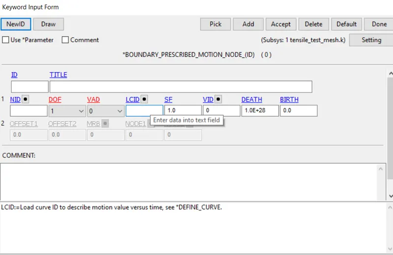
For example we can take the example of the boundary prescribed motion node card which uses to give a certain motion or displacement to given node as shown , we define a load curve id :
2.*Constrained
This is used to add two bodies or create a new rigid body or we can create new mechanical joints .
Let us take the example of :
Constrained Nodal rigid body : This is used to connect multiple nodes by the creation of a single node . A master node is created and slave nodes are created .
Constrained Rigid Body : This is used to model the bolts as shown below :
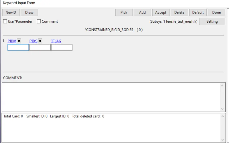
This contains the master rigid body which is connected to multiple slave rigid bodies and hence they move togethr after connection like a bolt .
3.*Load
This is used to define load on the body .
Now we will discuss the output files of LS DYNA :
There are two types of output files in ls dyna binary files and s key files . An s key file can be opened in notepad while binary file cannot be opened in notepad
1.D3PLOT : This card is used to write the animation files at certain intervals .
2.ACIIbinary : This is used to plot all the forces and energies.
Now we will talk about the contact cards and its theory:
There are 4 types of contatcs :
1. Type 1 : In this contact one of the parts has so high stiffness , that it has very less deformation compared to the lesser stiff part .
2.Type 2 : In this contact both of the have comparable stiffness and hence both have good amount of stiffness ,
3.Type 3 : Self contact , one part collides with itself
4. Type 4 : Tied Contact : This is used to glue two parts together .
Contact Cards in LS DYNA :
There is automatic and non automatic contact card which has the differences of :
In non automatic the normal of one part and other part should be facing each other and hence only than the contact will be working properly .
In other one this is not required and does it automatically .
Now we simulate the following :
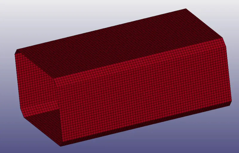
Now looking at the keyword manager we get to see :
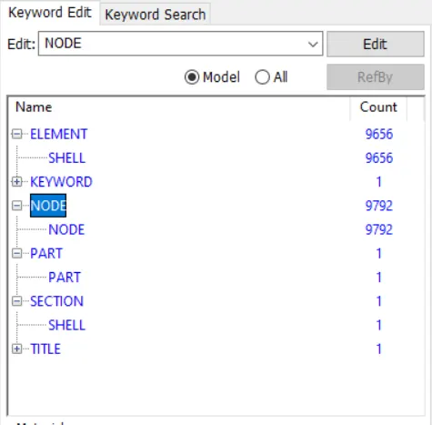
Hence the following cards are added for our crash simulations :
1. Self Contact Card :
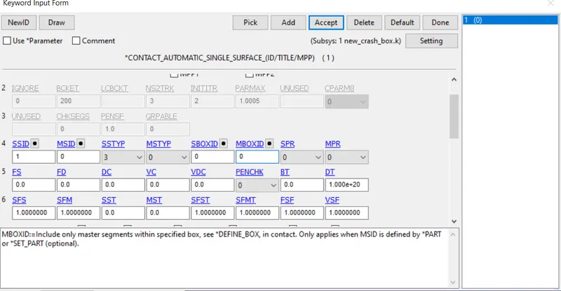
Here we are assuming there will be self contact in the contact and hence we will need the automatic single surface contact card and define the part in it .
2. Run Time Card :
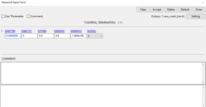
We have used this card to define the run time of our problem which is 5 seconds .
3. Output Cards :
We have requested for ACIIBINART AND 3DPLOT files as shown below :
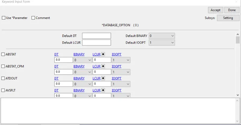
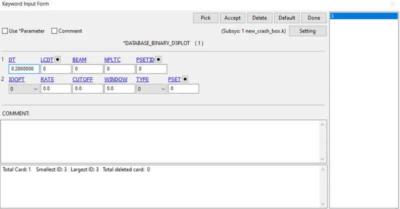
4.Rigid Wall Card :
We have created the rigid wall card as shown below :
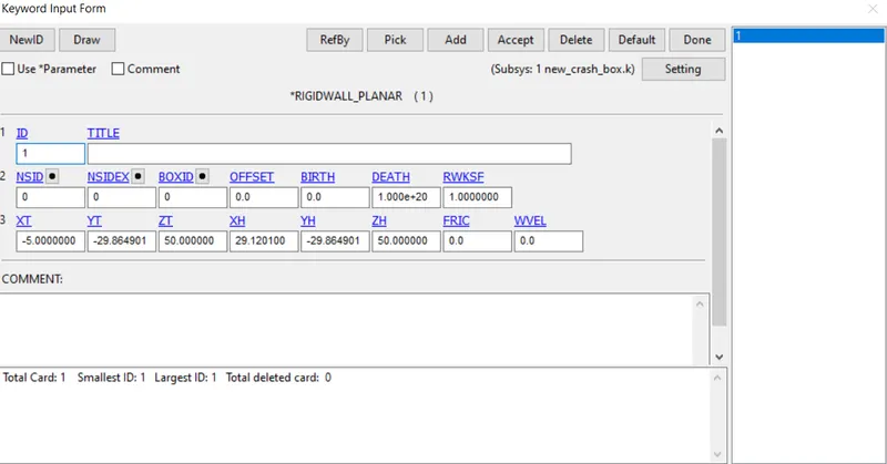
We have maintained a distance of 5 mm between the crash box and the rigid wall .
5. Material Card
Intially we have created the elastic material card as shown below :
6. Initial Velocity Card :
Now we will do the crash for the following cases :
Case 1 : Thickness = 1.2 mm , Material = Elastic
The following is the results :
1. Von Mises Stress :
2.Force at Middle Node :
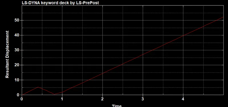
3.Section Force :
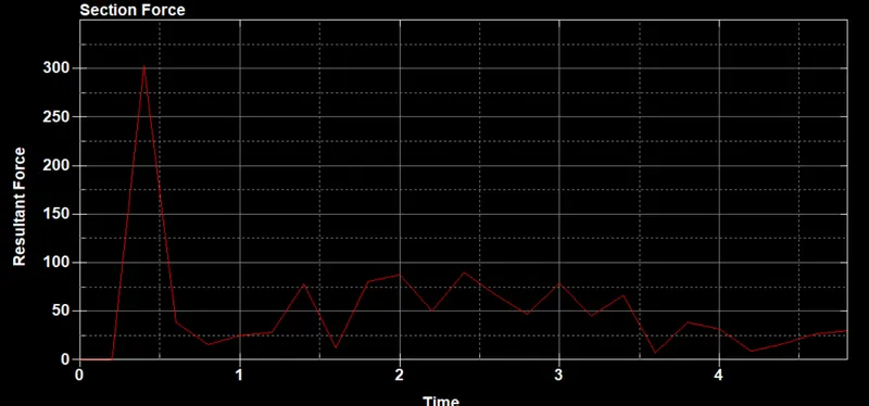
Case 2 : Case 1 : Thickness = 1.5 mm , Material = Elastic
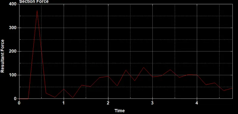
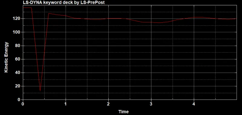
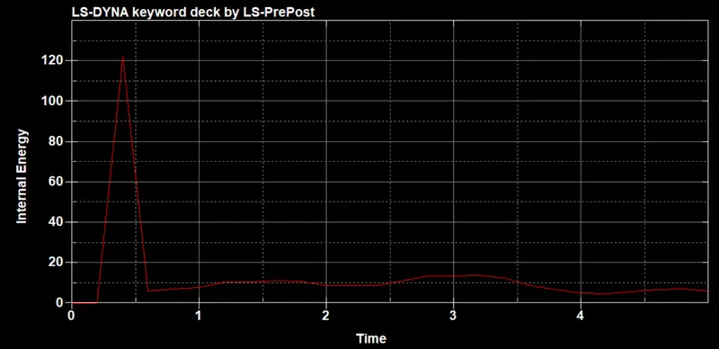
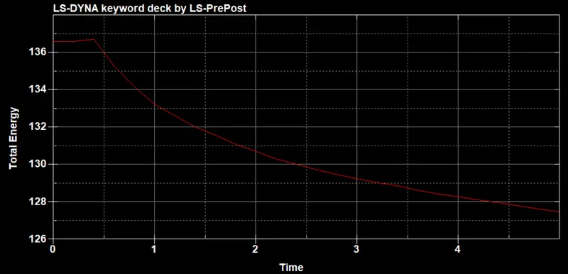
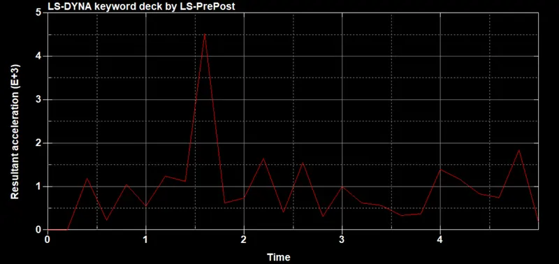
Conclusion :
Hence the simulation has been conducted