Week 4.1: Project - Steady state simulation of flow over a throttle body
Steady state simulation of flow over a throttle body
Introduction
Throttle is a mechanism often coined in relative to flow of fluids, responsible for controlling its flow across the pipe, by constriction or obstruction. The present study is about a butterfly throttle that uses obstruction to control flow of air across the pipe.
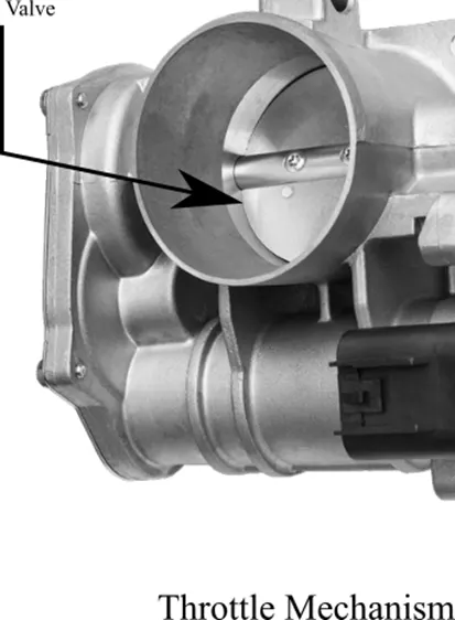
Throttle mechanism find its use in areas where fluid mixing is prevalent. It is often used to control the mixing components concentration by regulating the amount of fluid it allows to pass through.
Objective
To set-up steady state simulation of flow over a throttle body. The channel of flow is a circular pipe with a defined diameter.
Outline
The simulation is set as per objective i.e., a steady state simulation, in which throttle orientation is fixed. The fixed orientation of throttle body doesn’t allow mass flow rate to change.
Simulation
The geometry (STL) file of the pipe with valve has been adapted from the given source. The thickness of the pipe is eliminated as, our objective is to simulate the flow in the pipe. We are not interested in any temperature simulation concerning temperature change across pipe thickness.
Materials
Air is chosen as the fluid of interest for the simulation.
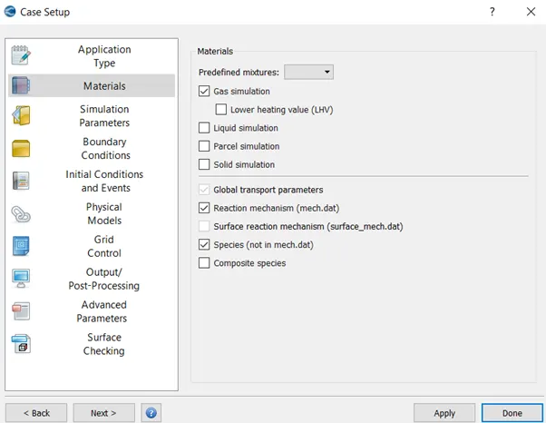
Default Gas transport for air has been chosen.
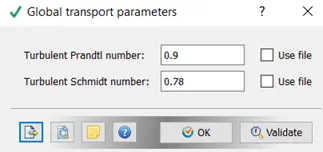
Geometry
The adapted pipe with throttle geometry has thickness in the pipe. Since our interest lies in the fluid flow inside of pipe, the thickness as been eliminated. Since after elimination of thickness, along the endpoints of pipe, the open edges have formed, which was eliminated using patch tool.
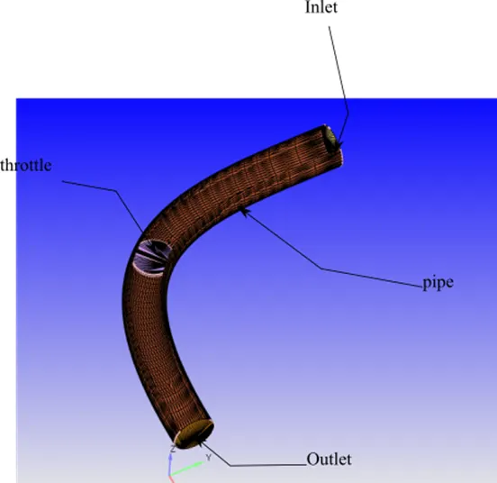
Final geometry after the modification is a shown below. A plane has been introduced for viewing the throttle (It is temporary modification for the sake of vision clarity).
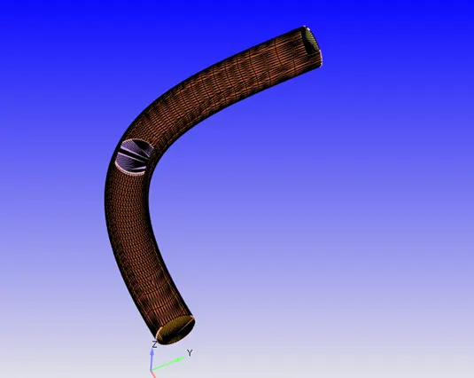
Later the geometry has been scaled into meters by using scale of 0.001.
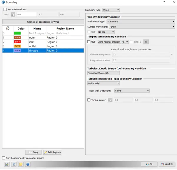
The boundary features with name are as follows: -
Boundary Condition
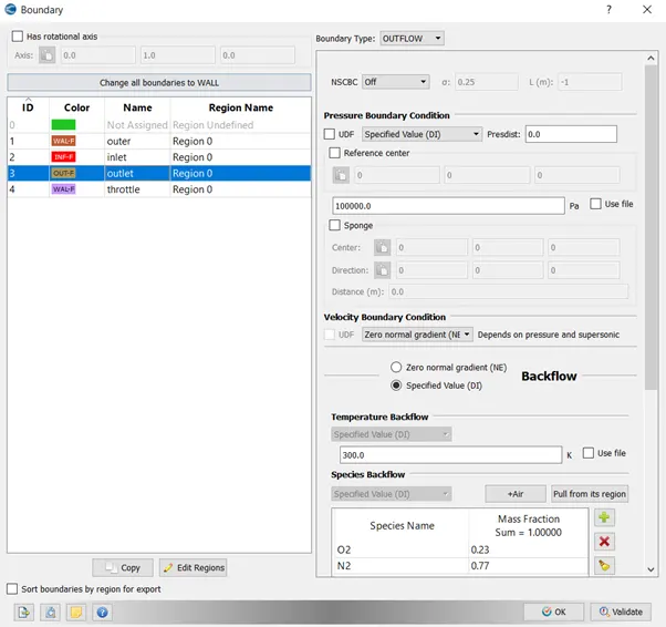
Outlet
Outlet has been given outflow boundary condition. With the species same as air and back flow temperature of 300k.
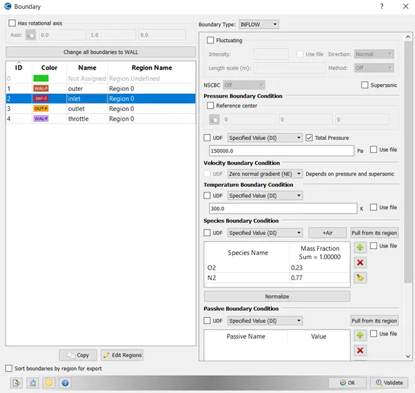
Inlet
Inlet has been given inflow boundary condition, with the specified value of pressure 150000.0 Pa
The inflow species is same as outflow.
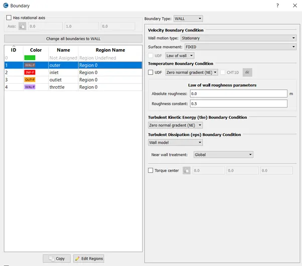
Outer
It has been assigned a wall type boundary.
Throttle
Throttle is also given wall type of boundary.
Solver
Run Parameters
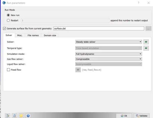
Steady State Solver was used to solve the computational problem.
Steady State Monitor
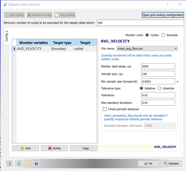
Average Velocity at outlet is chosen as the steady state monitor to check for convergence. 5000 cycle is chosen as the first check for convergence. The sample size is chosen to be 100.
Simulation Time Parameters
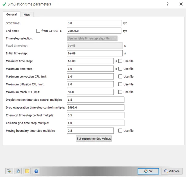
The simulation is set to run for maximum of 25000 cycles. The minimum time step is chosen to be as low as 1e-9s and maximum to be of 1. Though Converge CFD selects the time step most appropriate time step.
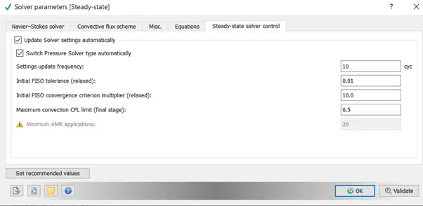
Maximum convection CFL Limit is chosen to be 1.
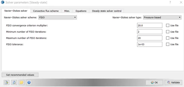
Solver parameters
Pressure based solver is used with 0.5 as final CFL no.
Grid
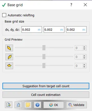
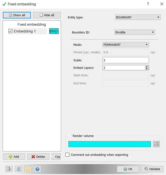
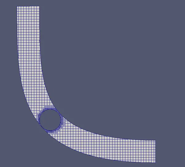
Base grid size of 2 mm has been defined. Fixed embedding around the throttle boundary has been enabled with a scale of 2. This will reduce the grid size by half. Also no. of layers for reduced grid size has been chosen as 2.
Turbulence Modelling
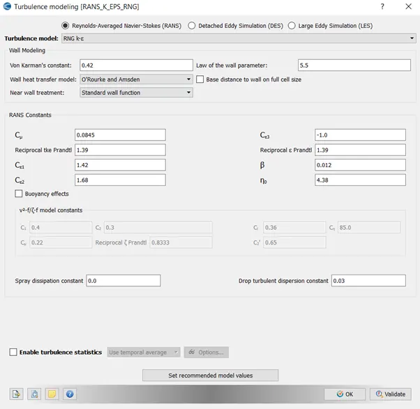
k-Epsilon turbulence model has been chosen for the particular analysis. The sub parameters have been chosen has default.
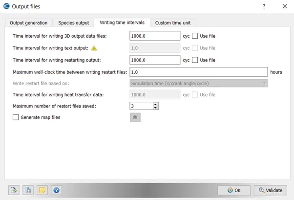
The default post variables have been given.
Output Files
Results and Discussion
Mesh at cut plane
Mesh at cut plane in Z direction shows high density near the throttle. Fixed Embedding near the throttle wall has minimized the size of elements.
Contour Plot
Pressure
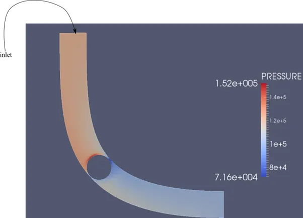
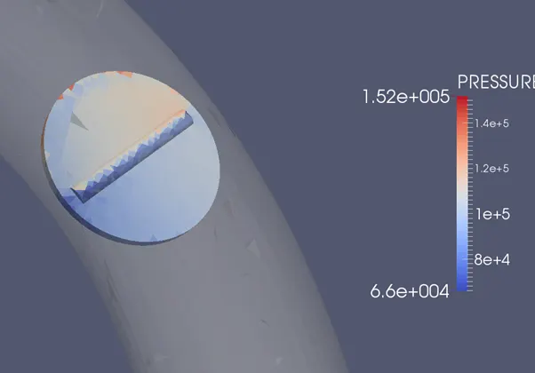
Pressure contour plot in the cut plane depicts the increased pressure region till the throttle valve. It is due to the obstruction in the flow path by throttle valve.
Velocity
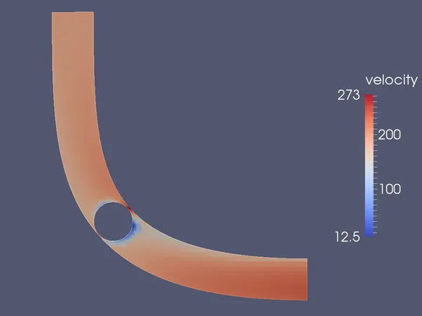
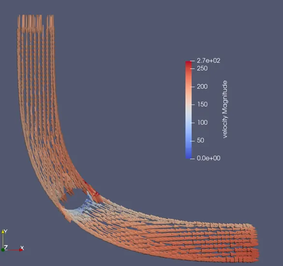
Velocity Contour plot shows high velocity near the edges of throttle disk. It is due to the sudden decrease in are of cross-section that leads to high velocity.
Line Plot
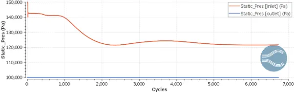
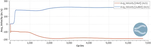
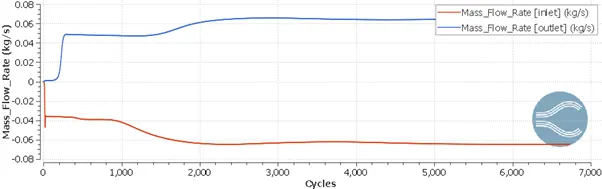
Area Average plot along the boundary wrt cycles.
Pressure
Velocity
Mass Flow Rate
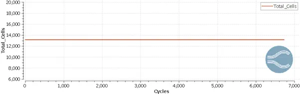
Total Cell Count
Velocity Vector
Pressure Contour Across Throttle
Conclusions:
- The steady state analysis has been done for the case of flow over throttle.
- Since the throttle obstructs the flow thus the inlet section possesses slightly raised Pressure.
- Following the conservation of mass law, steady state velocity has to be same in the inlet as well as outlet.
- Velocity around throttle has high fluctuation due to sudden change in cross-section area.
- Total Cell count is constant through the simulation as there is no dynamic mesh generation.