Week 9: Project 1 - Surface preparation and Boundary Flagging (PFI)
Project 1 - Surface preparation and Boundary Flagging (PFI)
Introduction
An internal combustion engine is a heat engine in which the combustion of a fuel occurs in a combustion chamber that is an integral part of the working fluid flow circuit. In an internal combustion engine, the expansion of the high-temperature and high-pressure gases produced by combustion applies direct force to the reciprocating piston, transforming chemical energy of fuel to the kinetic energy.
Objective
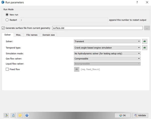
To set up a No-Hydro simulation of IC engine. No-Hydro simulation doesn’t take into account the physics of the problem, instead it focuses on the computational integrity of the dynamic problem. Its importance can be evaluated in terms of debugging an error when the source of error can me amalgamated with the physics as well as meshing issues.
Outline
The No-Hydro simulation setup is achieved in two phases, the boundary flagging and surface preparation.
No-Hydro Simulation
Geometry
Geometry has been imported in the converge from the source provided. After importing the geometry, diagnosis is done for error triangles.
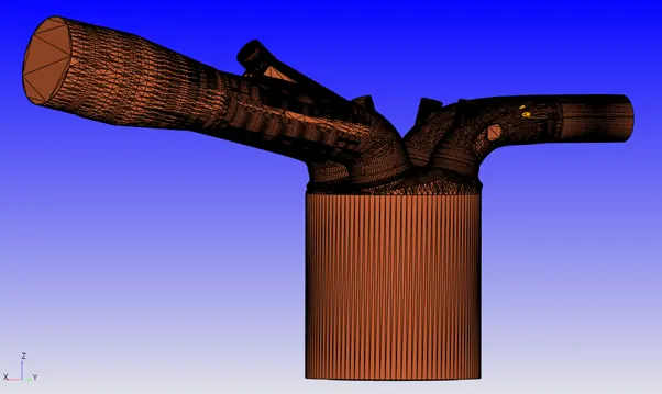
The image above is the raw imported geometry of the file from the source. The purple highlighted triangles represent error triangles, which can be later categorized among intersections, nonmanifold problems, open edges, overlapping triangles and normal orientation errors.
Set up is progressed further by flagging the boundaries as described below.
Boundary Flagging
Boundary Fencing using Arc Selection has been used to mark fences across different boundaries as described below.
Using Angle Selection with a tolerance for selecting the piston surface.
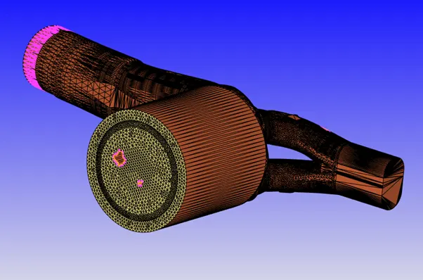
Fencing was used to select the liner boundaries as shown below.
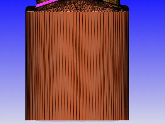
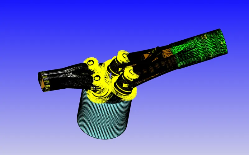
Inlet geometry contains some interference as can be seen from the imported STL file. The issue has been addressed by selecting the valves and translating it to remove the interference.
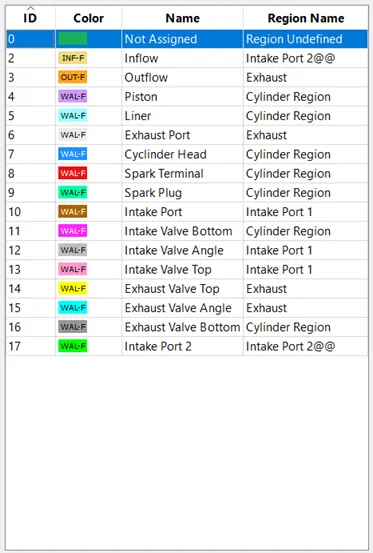
The boundary flagging of engines components are as follows.
Liner
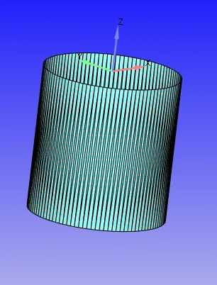
Inlet port Divided into 2 parts along with inflow boundary
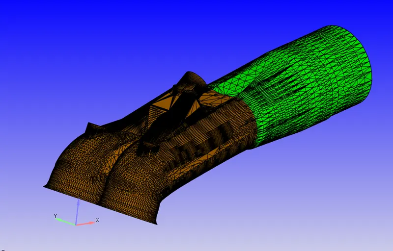
Exhaust Port with Outflow
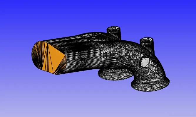
Cylinder head
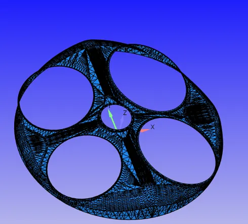
Intake Valves separated in top angle and bottom boundary
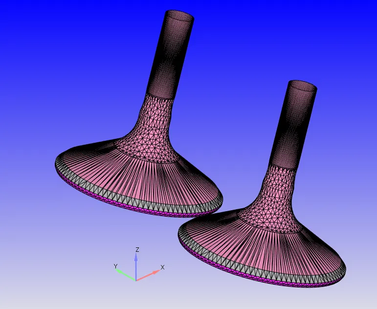
Exhaust Valves separated in top angle and bottom boundary
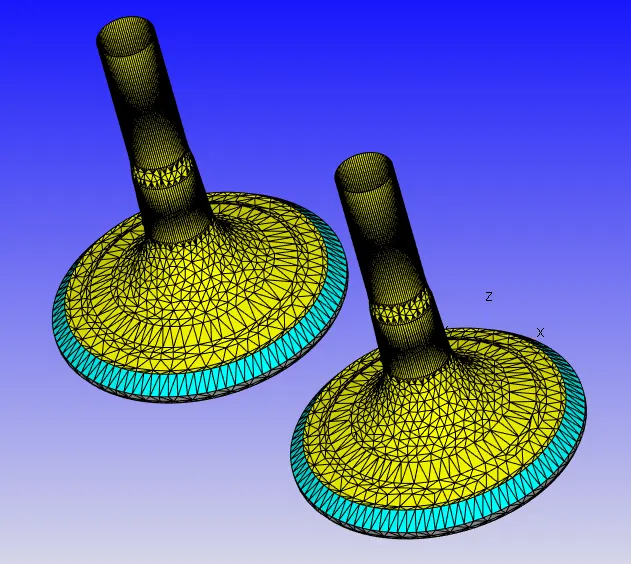
Spark Terminal
Surface Preparation
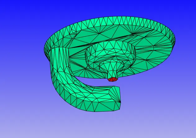
Surface patching has been used to seal the open edges of the surface.
The triangle normal vectors were then corrected to point inside of the geometry to attain the fluid zone.
Simulation
Application Type
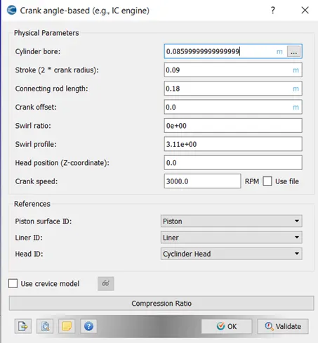
Crank Angle Based Simulation
Material
Air with default properties has been used as the material as we are not interested in simulating the chemical combustion. Isooctane (IC8H18) has been selected as a fuel material. Respective reaction mechanism has been applied as been provide from the source.
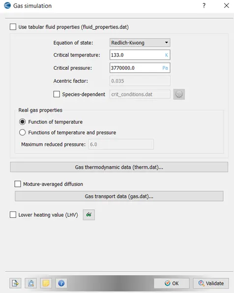
Simulation Parameters
Run Parameters
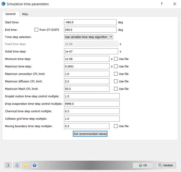
Simulation Time Parameters
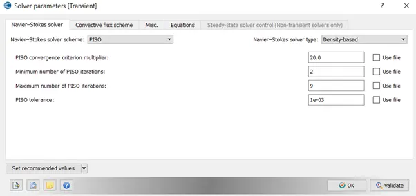
Solver Parameters
Boundary and Regions
Declaration of Regions
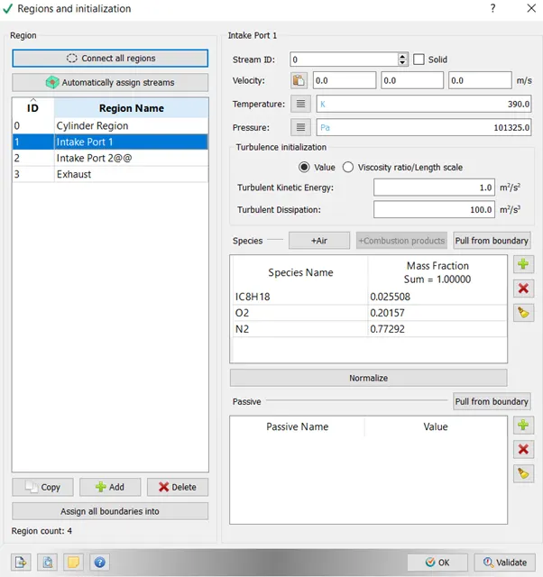
Intake Port 1
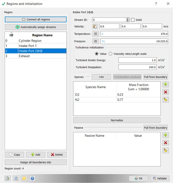
Intake Port 2
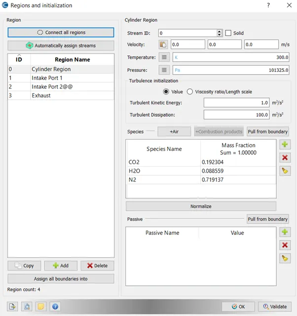
Cylinder Region
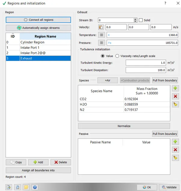
Exhaust
Boundaries
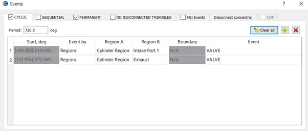
Events
Grid
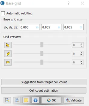
Base Grid
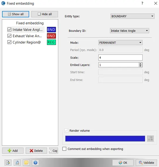
Fixed Embedding
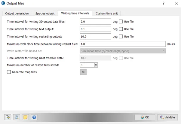
Output Files
Geometry Animation
Animation of Mesh