Week 10 - Simulating Combustion of Natural Gas.
Simulating Combustion of Natural Gas
Objective
Following are the objective of the present study:
- To perform a combustion simulation on the combustor model
- To add the water content in the fuel from 5% to 30% by mole and observe the effect of it on the results.
Outline
In order to achieve the above stated objective, the study has been planned with 2 cases. In the first case, the combustion simulation has been done with fuel injection only without water added to it. In the second case water along with fuel is added to observe the effects on pollutants being produced.
The case study has been planned as:
Case 1
Combustion simulation has been done to observe the presence of toxic pollutants apart from other by products.
Case 2
As a measure to reduce the pollutants like NOx and Soot particles, addition of water has been simulated. Water has been added as a molar fraction along with methane. The percentage of water has been varied from 0% to 30% with a difference of 5%.
Simulation Set-Up
Ansys workbench Mechanical has been used to set up and solve the computational problem. Model creation starts with geometry modelling as discussed below.
Geometry
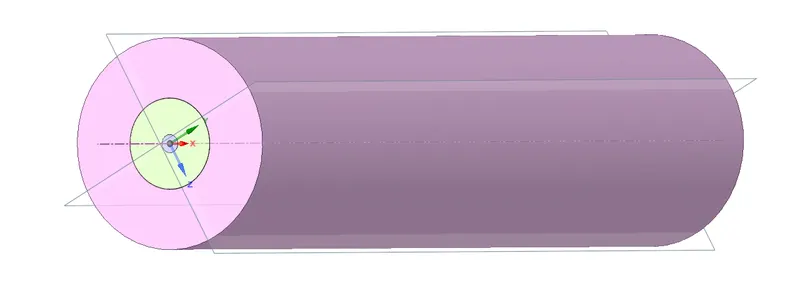
The geometry has been adapted from the source provided. The modification and simplification have been done in ANSYS SpaceClaim module.
Below is the adapted geometry model of combustion chamber.
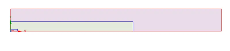
In order to reduce the number of elements counts and decrease the computational cost of simulation, the domain has been turned into axisymmetric 2D geometry as presented below.
Since the geometry contains various parts, the interference has been checked and the bodies has been subjected to share the topology. It has been done using workbench -> Share function in SpaceClaim.
Further the geometry has been utilized for meshing which has been covered in the next section.
Meshing
The development of computational mesh has been achieved in the Ansys meshing module. Before creating the mesh domain, the geometry features has been selected and named, as included in the named selection.
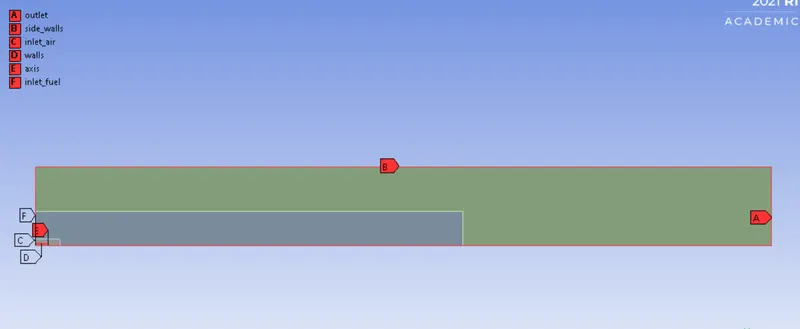
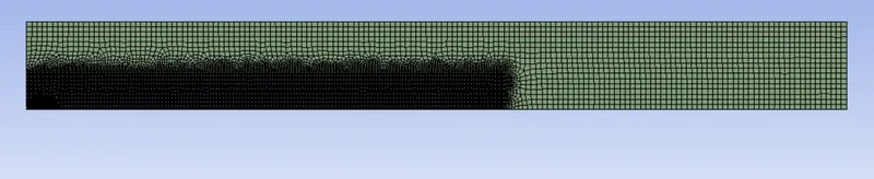
Meshing feature (Sizing) has been applied on the 3 different surfaces in the geometry. In the inner most region of inlet, element size is of 0.0005m, whereas the surface adjacent to it has an element size of 0.001. The outermost region has been given the element size of 0.005m.
The complete mesh has been presented below:
Solver Settings
General Settings
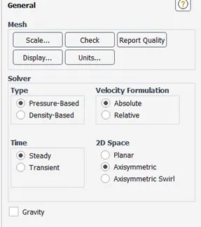
Axisymmetry has been enabled in the solver settings
Energy equation

Energy equation has been solved for the computational problem.
Viscous Model
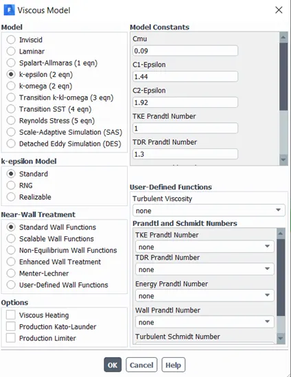
K epsilon model with standard wall function has been used in the present model.
Species Model
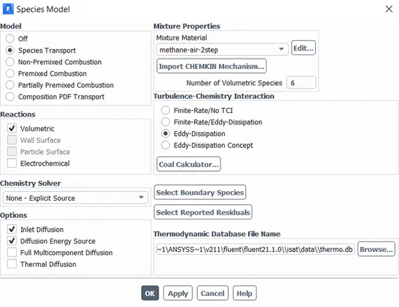
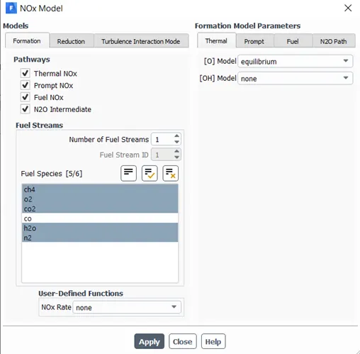
NOx
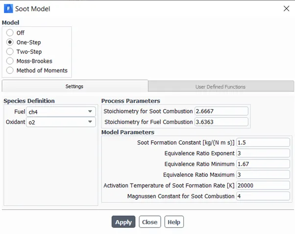
Soot Model
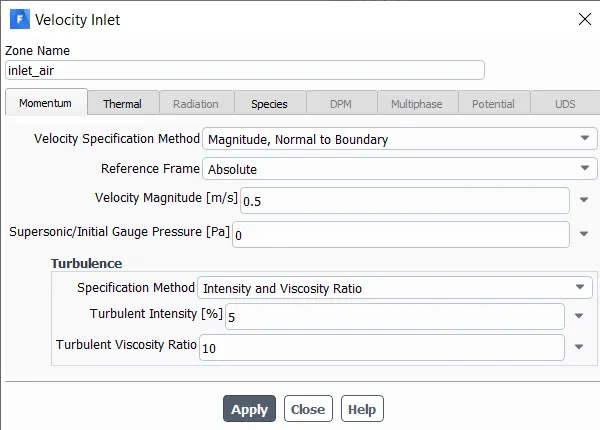
Air Inlet Boundary Condition
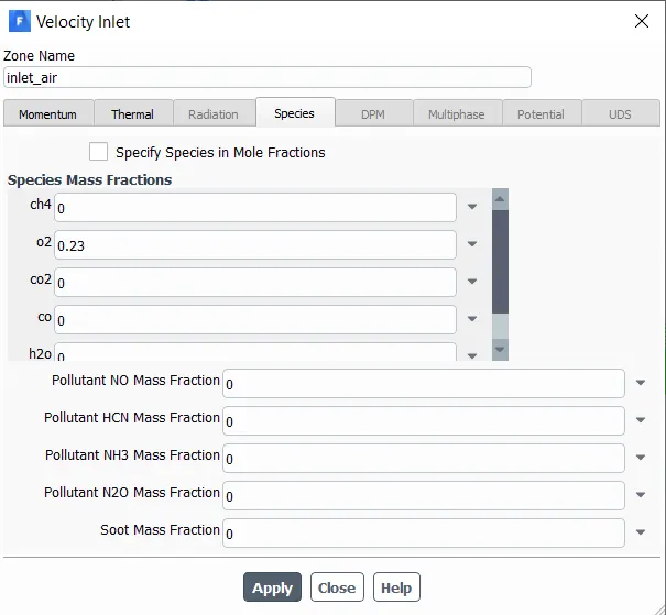
Air Inlet species Boundary COndition
Fuel Inlet Boundary COndition
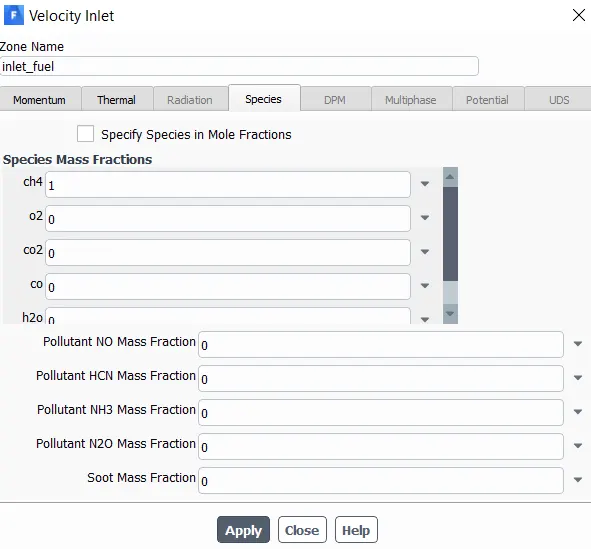
Fuel inlet has been changed from mass fraction to mole fraction in the cases where there is introduction of H2O
Fuel Inlet Species Boundary Condition
Variable Recording methodology
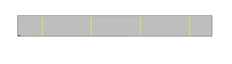
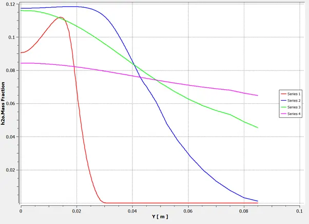
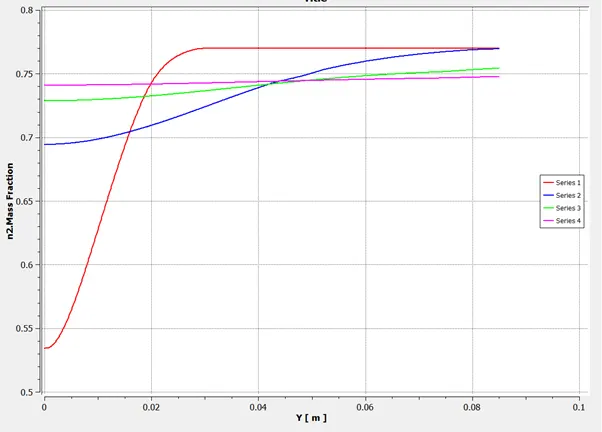
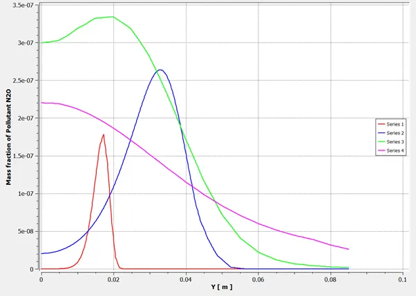
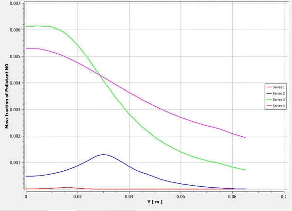
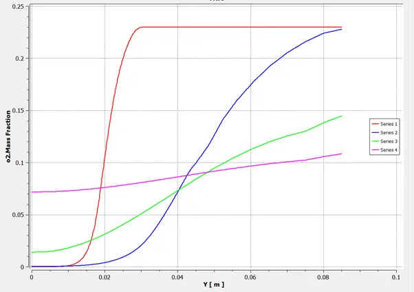
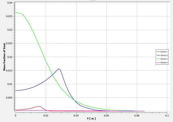
The line shown in the above figure represents the variable recording paths. Mass fraction has been recorded on those paths.
Results and Discussion
Residual Plot
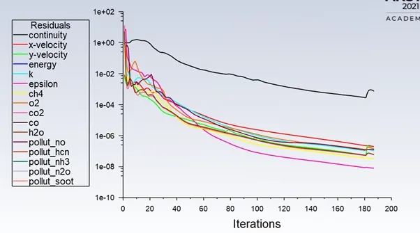
The residual plot suggests that the computational problem has effectively converged.
Case 1
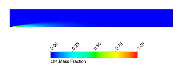
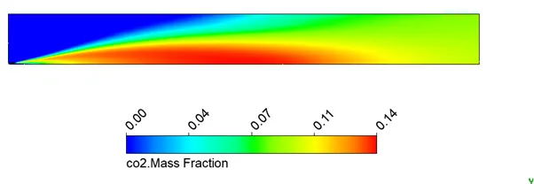
Contour Plot of Mass Fraction of different species
CH4
CO2
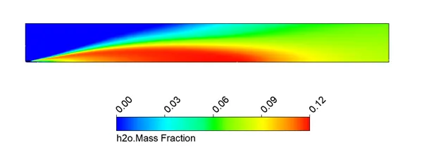
H2O
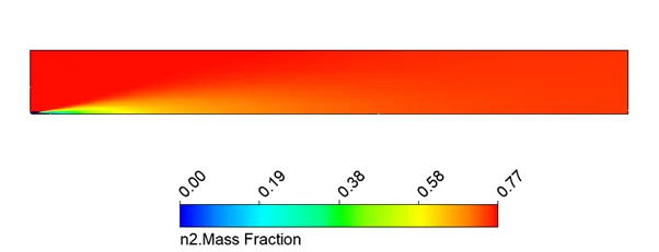
N2
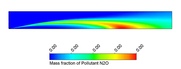
N2O
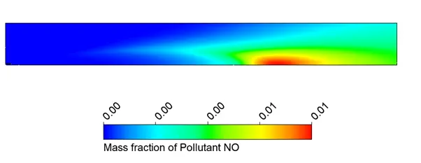
NO
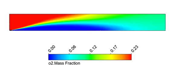
O2
Soot
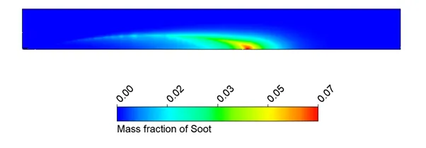
Chart Plot of Mass Fraction of different species
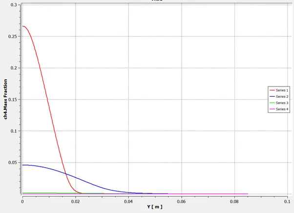
CH4
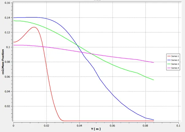
CO2
H20
N2
N2O
NO
O2
Soot
Case 2
0%
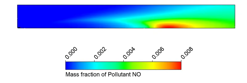
NO Contour Plot
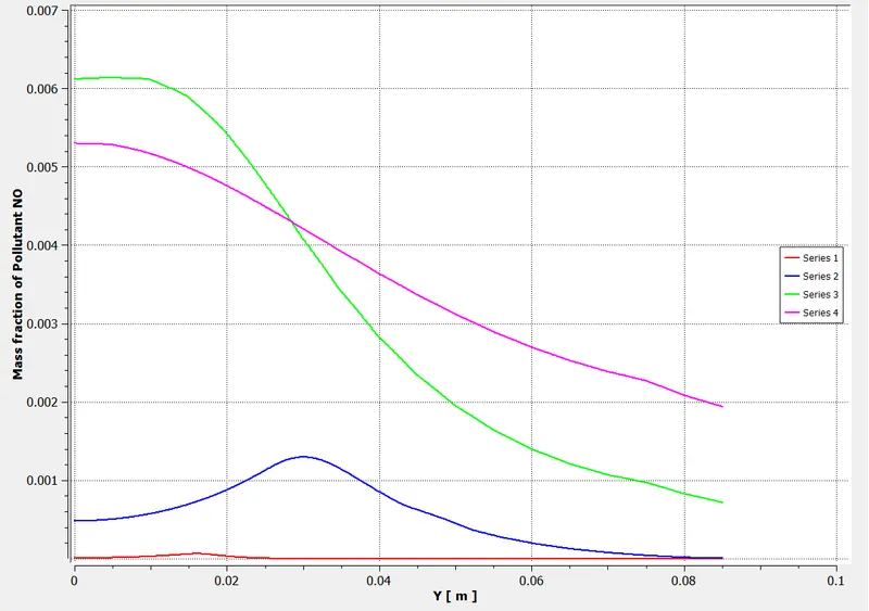
NO Chart plot
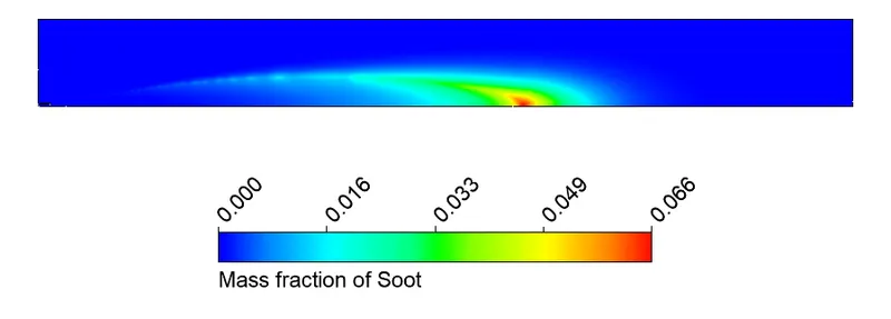
Soot Material Contour Plot
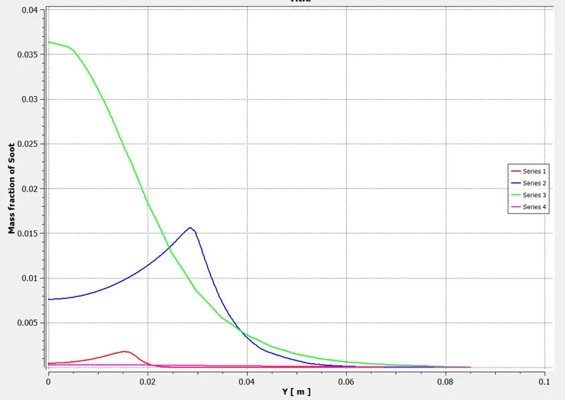
Soot Material Chart Plot
5%
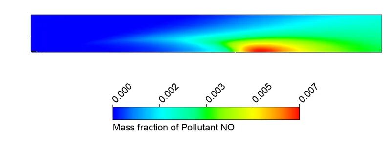
NO Contour Plot
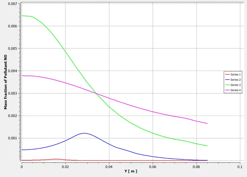
NO chart plot
Soot Material Contour Plot

Soot Chart Plot
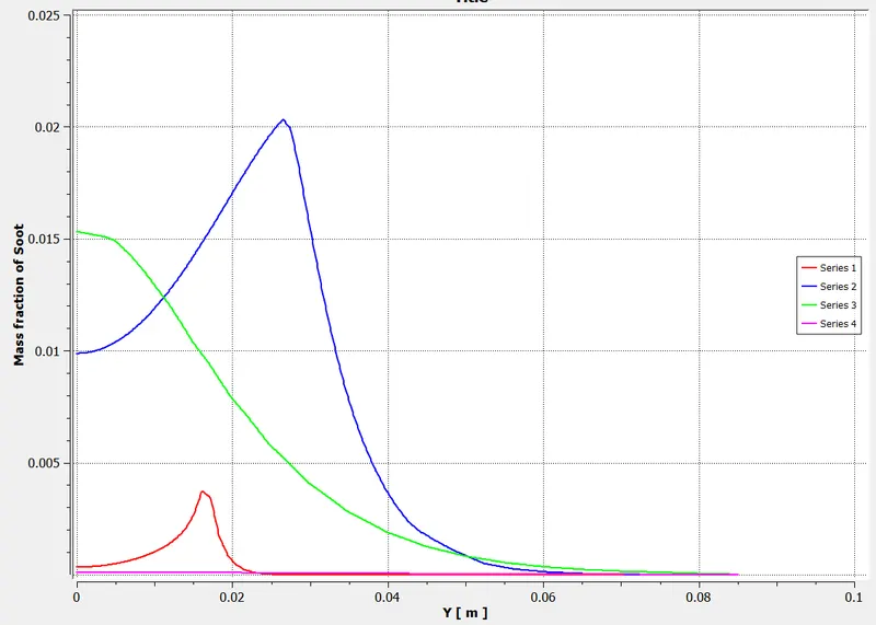
10%
NO Contour Plot
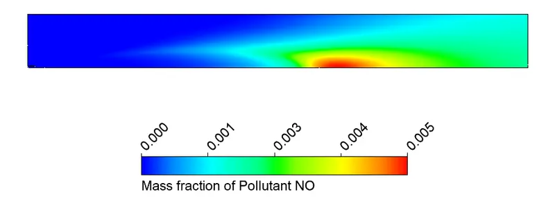
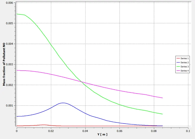
NO chart Plot
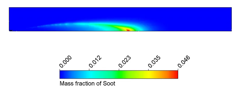
Soot Material Contour Plot
Soot material chart plot
15%
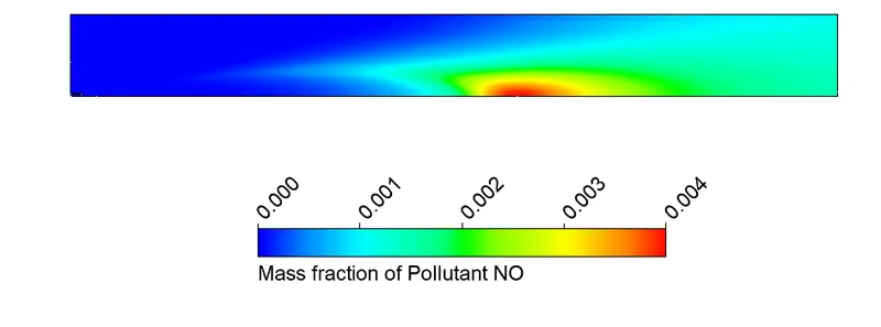
NO Contour Plot
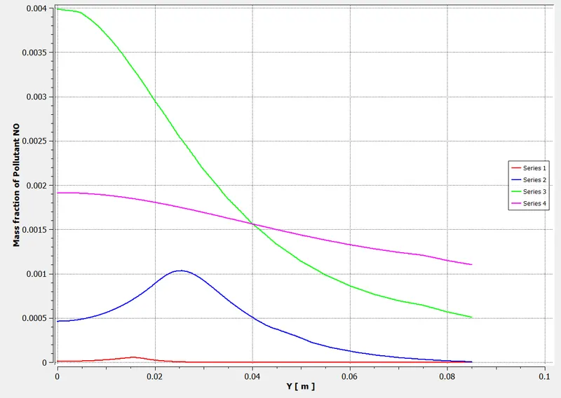
NO chart plot
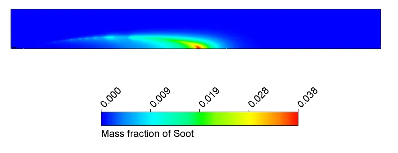
Soot Material Contour Plot
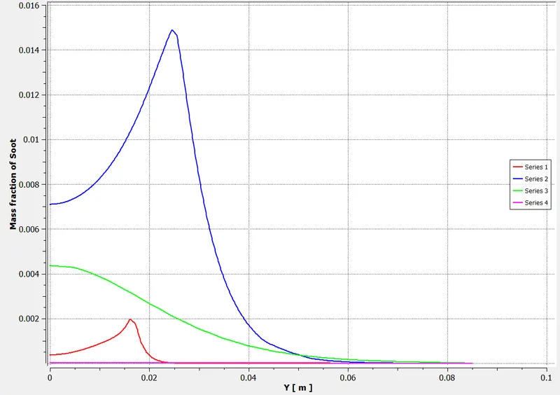
Soot Chart Plot
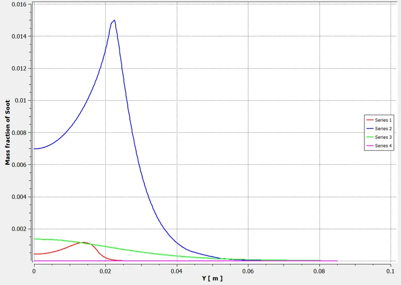
20%
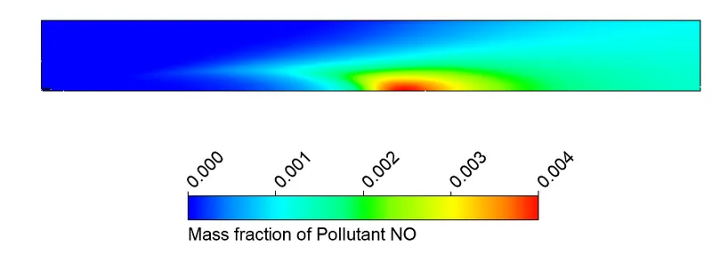
NO Contour Plot
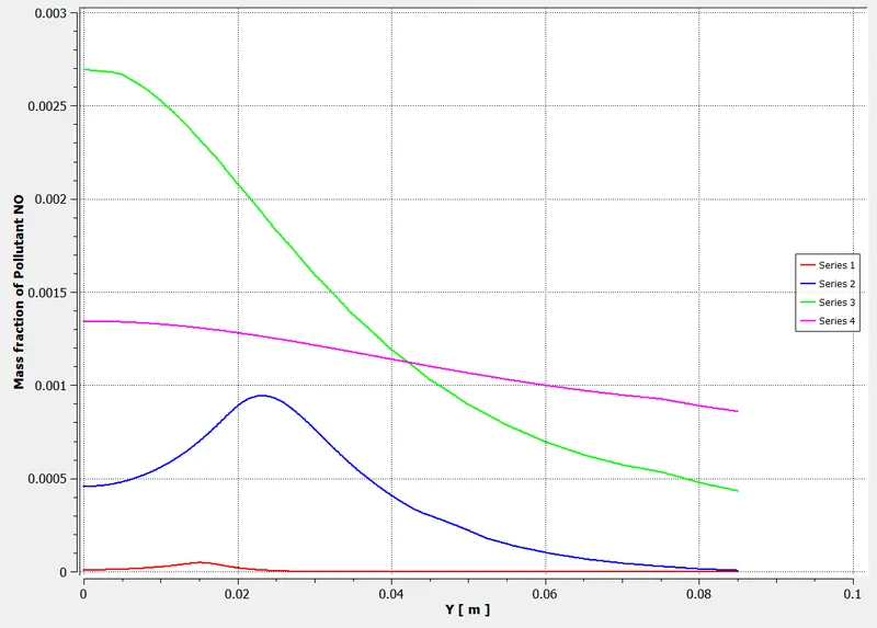
NO chart plot
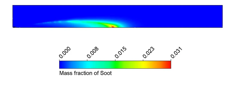
Soot Material Contour Plot
Soot Material Chart Plot
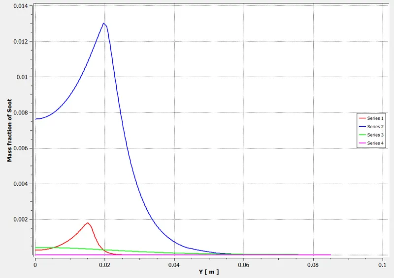
25%
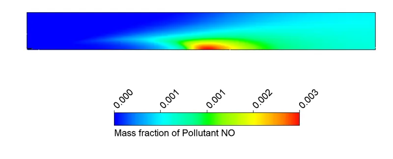
NO Contour Plot
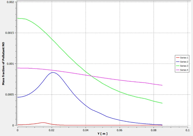
NO Chart Plot
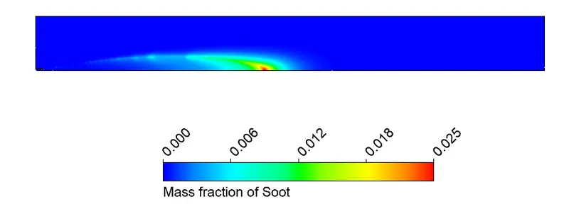
Soot Material Contour Plot
Soot Chart Plot
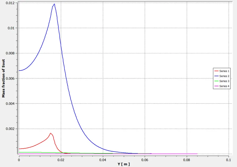
30%
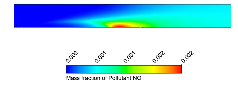
NO Contour Plot
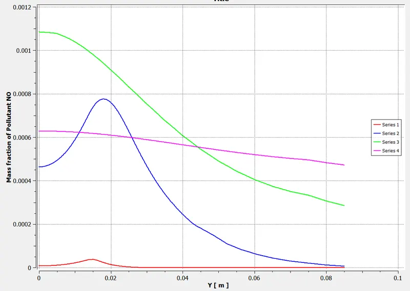
NO chart plot
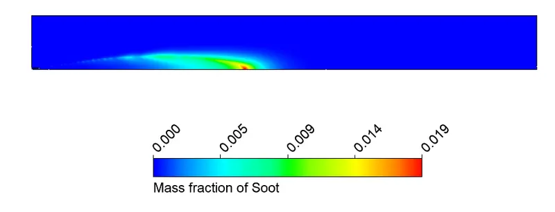
Soot Material Contour Plot
Soot Material Chart Plot
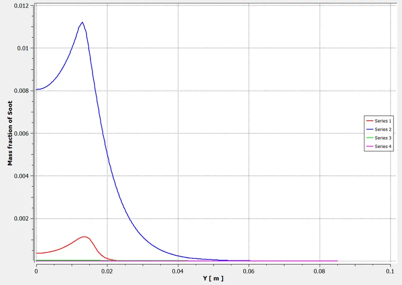
It is evident from the simulation and above plot that introduction of H2O readily reduces the amount of toxic pollutants like NOx and Soot particles.