Week 4.2: Project - Transient simulation of flow over a throttle body
Transient Simulation of Flow Over a Throttle Body
Introduction
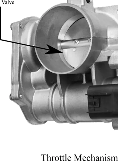
Throttle mechanism is often used as a measure of controlled flow of fluid. It is one of the mechanisms that uses obstruction in flow path of fluid.
Objective
To set-up steady state simulation of flow over a throttle body. The channel of flow is a circular pipe with a defined diameter.
Outline
The simulation is set as per objective i.e., a transient simulation, in which throttle orientation is varied by 25 degrees in 0.02 seconds.
Simulation
The geometry (STL) file of the pipe with valve has been adapted from the given source. The thickness of the pipe is eliminated as, our objective is to simulate the flow in the pipe. We are not interested in any temperature simulation concerning temperature change across pipe thickness.
Geometry
The adapted pipe with throttle geometry has thickness in the pipe. Since our interest lies in the fluid flow inside of pipe, the thickness has been eliminated. Since after elimination of thickness, along the endpoints of pipe, the open edges have formed, which was eliminated using patch tool.
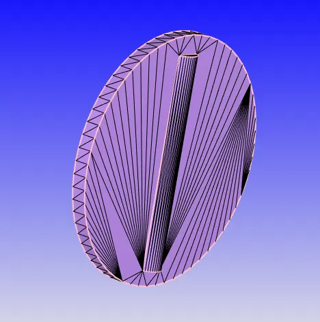
Final geometry after the modification is a shown below. A plane has been introduced for viewing the throttle (It is temporary modification for the sake of vision clarity).
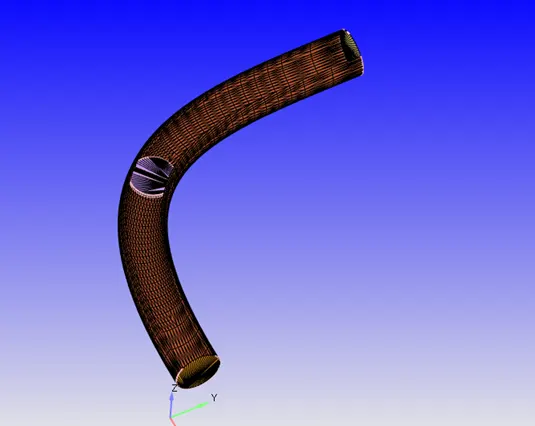
Later the geometry has been scaled into meters by using scale of 0.001.
Boundary
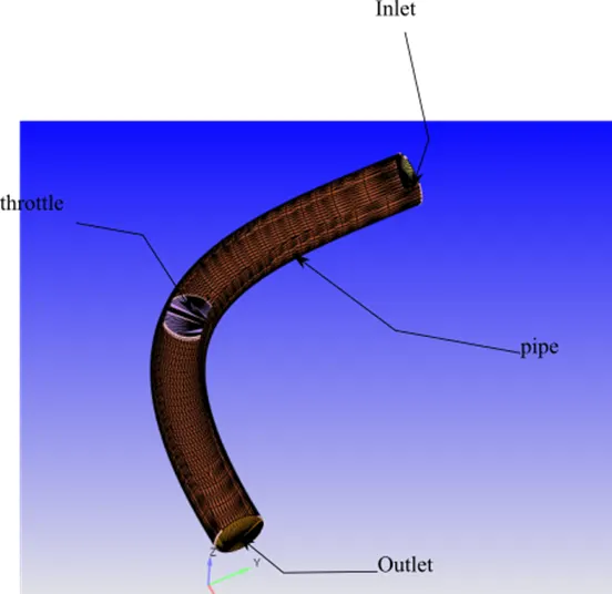
The boundary features with name are as follows: -
Boundary Conditions
Inlet
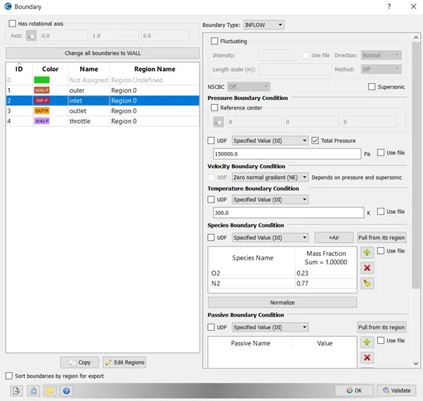
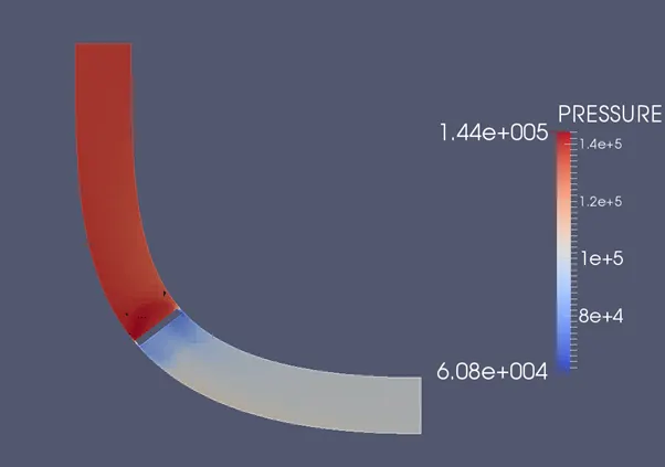
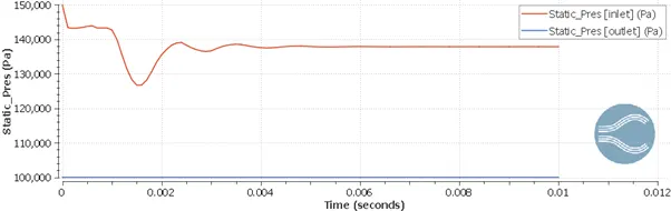
Inlet has been given inflow boundary condition, with the specified value of pressure 150000.0 Pa
The inflow species is Air.
Outlet
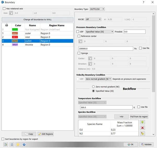
Outlet has been given outflow boundary condition. With the species same as air and back flow temperature of 300k.
Outer
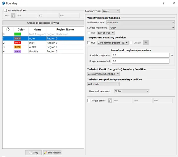
It has been assigned a wall type boundary.
Throttle
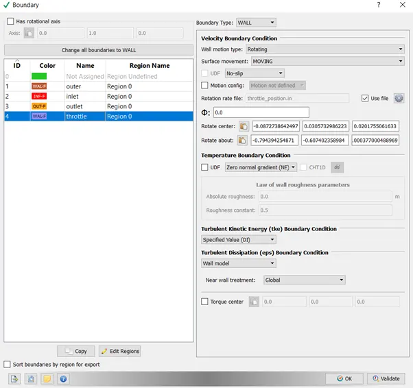
Throttle has been assigned a boundary of type wall. The throttle is not marked as stationary, instead it is of rotary. The rotation axis is same as that of rib cylinder on throttle butterfly plate. The rotation center is the center of the circular periphery of the cylinder.
Material
Air is chosen as the fluid of interest for the simulation.
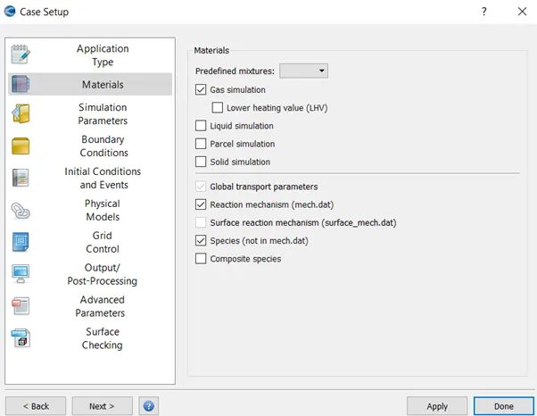
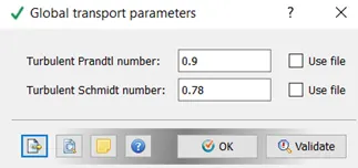
Default Gas transport for air has been chosen.
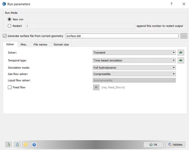
Solver
Run Parameters
Transient Simulation was used to solve the computational problem.
Simulation Time Parameter
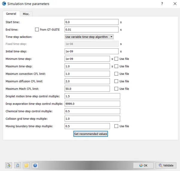
End time of simulation is chosen such that, water will be able to flow through the entire pipe in computational domain.
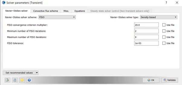
Solver Parameters
Grid
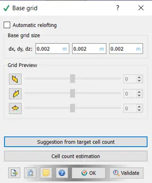
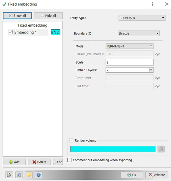
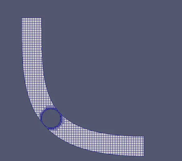
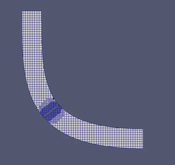
Base grid size of 2 mm has been defined. Fixed embedding around the throttle boundary has been enabled with a scale of 2. This will reduce the grid size by half. Also no. of layers for reduced grid size has been chosen as 2.
Turbulence Modelling
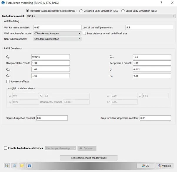
k-Epsilon turbulence model has been chosen for the particular analysis. The sub parameters have been chosen has default.
Output Files
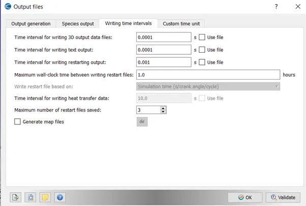
Time interval for writing the 3D output data files is chosen to be 0.0001 seconds.
Results and Discussion
Mesh
Mesh before valve turning
Mesh after valve turning
Contour Plot
Pressure
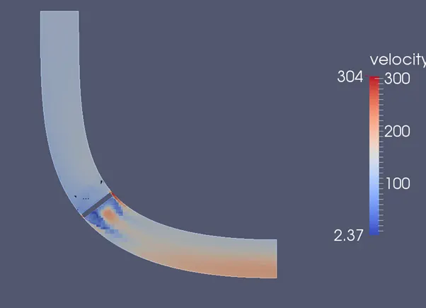
Velocity
Line Plot
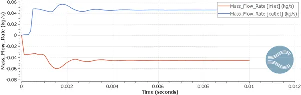
Mass Flow Rate
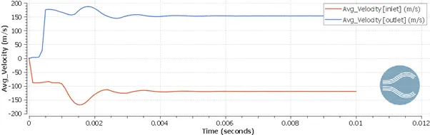
Velocity
Pressure
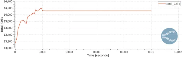
Cell Count
Animation
As compared to the previous steady state analysis, flow rate of mass fluctuates when the valve is turned to a degree. Then, it stablizes.
The movement of fluid is obstructed which causes sudden change in velocity, when the valve is turned.
Total cell count also changes while in simulation as, the valve rotates, it leads in variation in cell count.