Week 8 - Simulating Cyclone separator with Discrete Phase Modelling
Simulating Cyclone separator with Discrete Phase Modelling
Introduction
Cyclone separator are an economical device for removing particulate solids from a fluid system. Particle along with a working fluid gets introduced via a stream through inlet, the induced centrifugal force is tangentially imparted on the wall of the cyclone cylinder. This force, with the density difference between the fluid and solid, increases the relative settling velocity. The heavier particle tends to slid down and are trapped in the lower outlet pane. Though the cyclone separator are highly efficient, but its efficiency varies given the particle size and flow velocity. The particles sometimes tend to escape with the working fluid making it less efficient.
Some of the emperical models developed to study the seperation efficiency are as follows:-
Koch and Licht Model
This model assumes the tangential velocity of particle to be equal to that of tangential velocity of gas flow. This model takes into account of the turbulent nature of flow in the cyclone separator.
`etai = 1- exp{-2[{Gtau_iQ}/{D^3}(n+1)]^({0.5}/{n+1})}`
Li wang model
This model takes consideration of turbulent diffusion, particle bounce or re-entering.
`ni = 1 - exp{-lambdatheta_1}`
Iozia and Leith Model
The model assumes that a particle carried by the cortex endures the influence of two forces, namely a centrifugal force and a flow resistance. The model works on the basis of force balance of the given forces.
`ni = {1}/{1+({d_{pc}}/{d_{pi}})^beta}`
Lapple Model
This model doesn’t take into account for flow resistance. The model has been derived on the basis of force balance. The assumption of uniform distribution on the inlet surface was also taken into account.
`ni = {1}/{1+({d_(pc)}/{d_(pi)})^2}`
Objective
The objective is to study the effect of particle size and velocity on separation efficiency of the cyclone separator.
Outline
To Achieve the above objective the study has been planned as below:
- In the first series of study, the particle diameter has been varied from 1 to 5 micro meter, keeping the inlet velocity and particle injection velocity same. The inlet velocity of the particle and flow velocity was 3m/s.
- In the second series of study, the particle velocity has been kept constant and velocity of inlet has been varied from 1 to 5 m/s. The particle velocity is assumed to be same as that of flow velocity. The particle velocity is assumed to be 5 micro meter.
The first series of study will be helpful in observing effect of particle size on cyclone separation efficiency. Whereas, the second series of study will be helpful in observing the effect of inlet velocity on separation efficiency.
Computational Modelling
Computational model has been developed in Ansys Mechanical workbench using Ansys fluent module.
Geometry
The geometry was used as provided in the source. Ansys-SpaceClaim has been used to modify the geometry for further analysis. Since the geometry has no multi-component attachments, volume extraction has been done after importing the model. There are 2 outlets and one inlet section in the geometry as described in the image below.
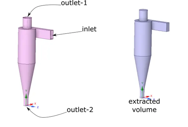
Volume extraction has been done using volume extract command in the Ansys-SpaceClaim.
Meshing
The developed geometry - extracted volume later was used for meshing the computational domain. The boundary names were added as named selection, for ease in application of boundary condition.
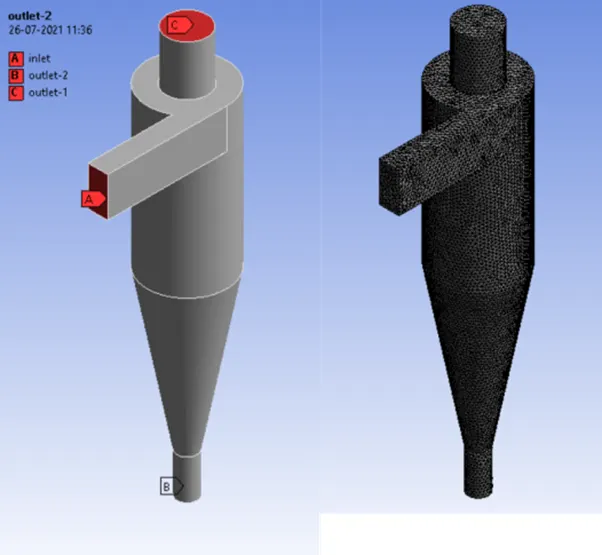
The element size of 0.008m was used to create the mesh.
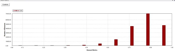
The element quality of the mesh is moderately good as presented below.
Solver Settings
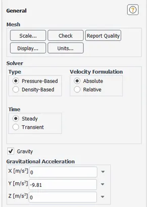
Since the model requires gravitational assisted particle trap, so the gravity has been enabled in the solver the negative of y direction.
Viscous Model
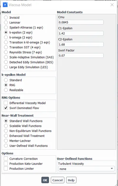
RNG - K epsilon model with standard wall functions has been used to model the turbulent flow for the present study. Swirl Dominated flow has been enabled in the RNG options. Precise calculation in the wall region is not necessary for the present study, so for the sake of simplicity the above-mentioned model has been used.
Discrete Phase Model
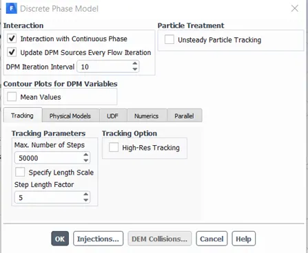
In the discrete phase model, interaction with continuous phase has been allowed. This enables a coupled calculation of the discrete phase and the continuous phase. Also, the model is to update the discrete phase source term in every DPM iteration.
Injection Properties
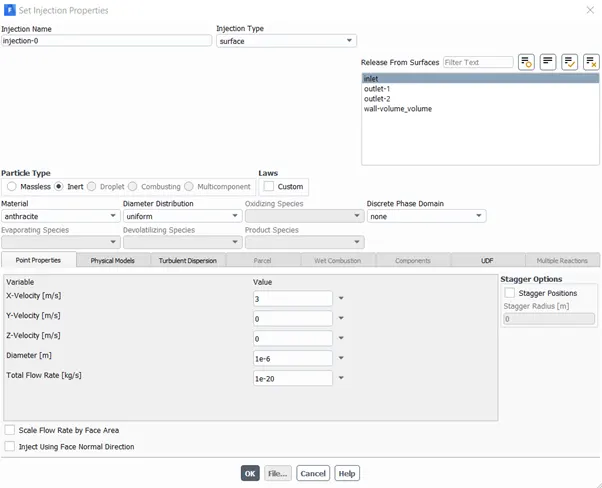
Injection type of surface was chosen as we are simulating injection via the inlet boundary. The material of injection is chosen to be anthracite. The diameter of the particles has been modified as per the case being studied, the same goes with the velocity of injecting particles.
Volume cell zone
Boundary Conditions
Inlet
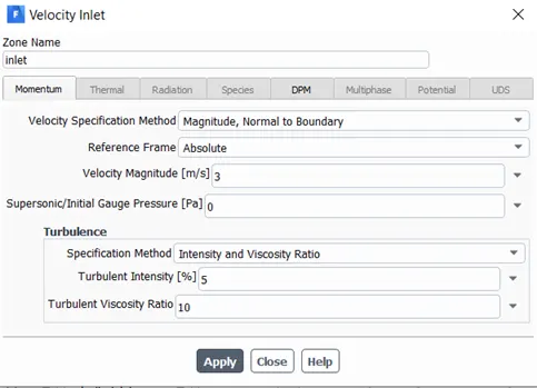
Inlet is a velocity type boundary; the magnitude of velocity will be varied as per the case studied.
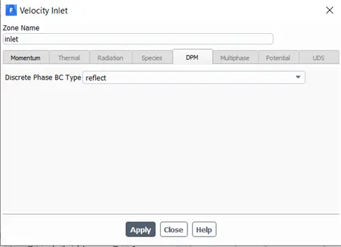
Inlet has been subjected as reflect boundary time for discrete phase modelling.
Outlet-1
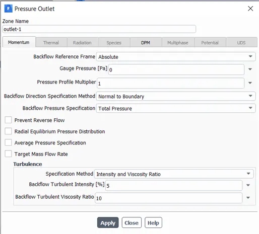
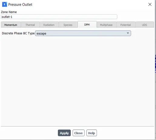
Outlet-1 is a pressure type boundary. It has been subjected as escape boundary time for discrete phase modelling.
Outlet-2
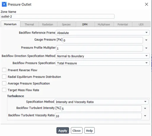
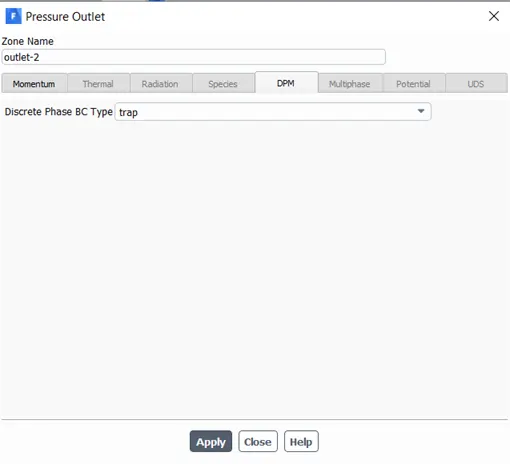
Outlet-2 is a pressure type boundary. It has been subjected as escape boundary time for discrete phase modelling.
Solution settings
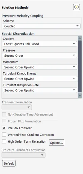
Results and Discussion
Residual Plot
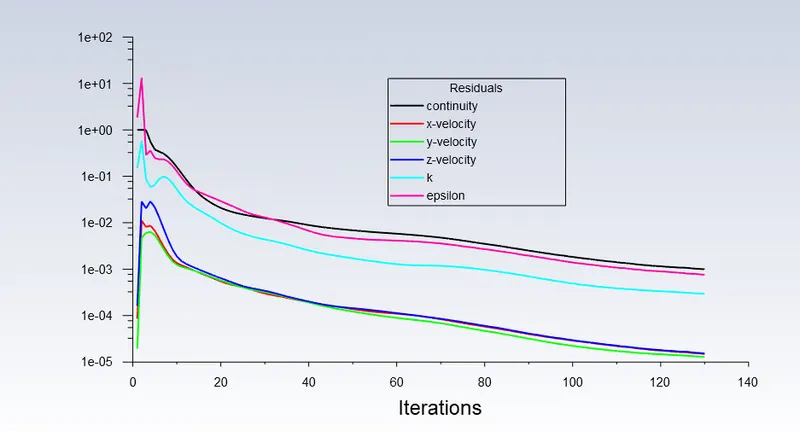
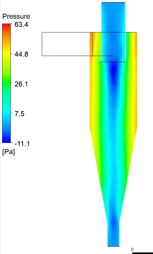
General Pressure Contour Developed in the cyclone seperator
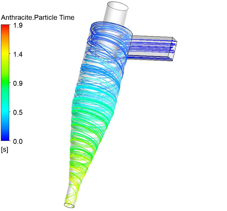
Particle time plot inside cyclone seperator
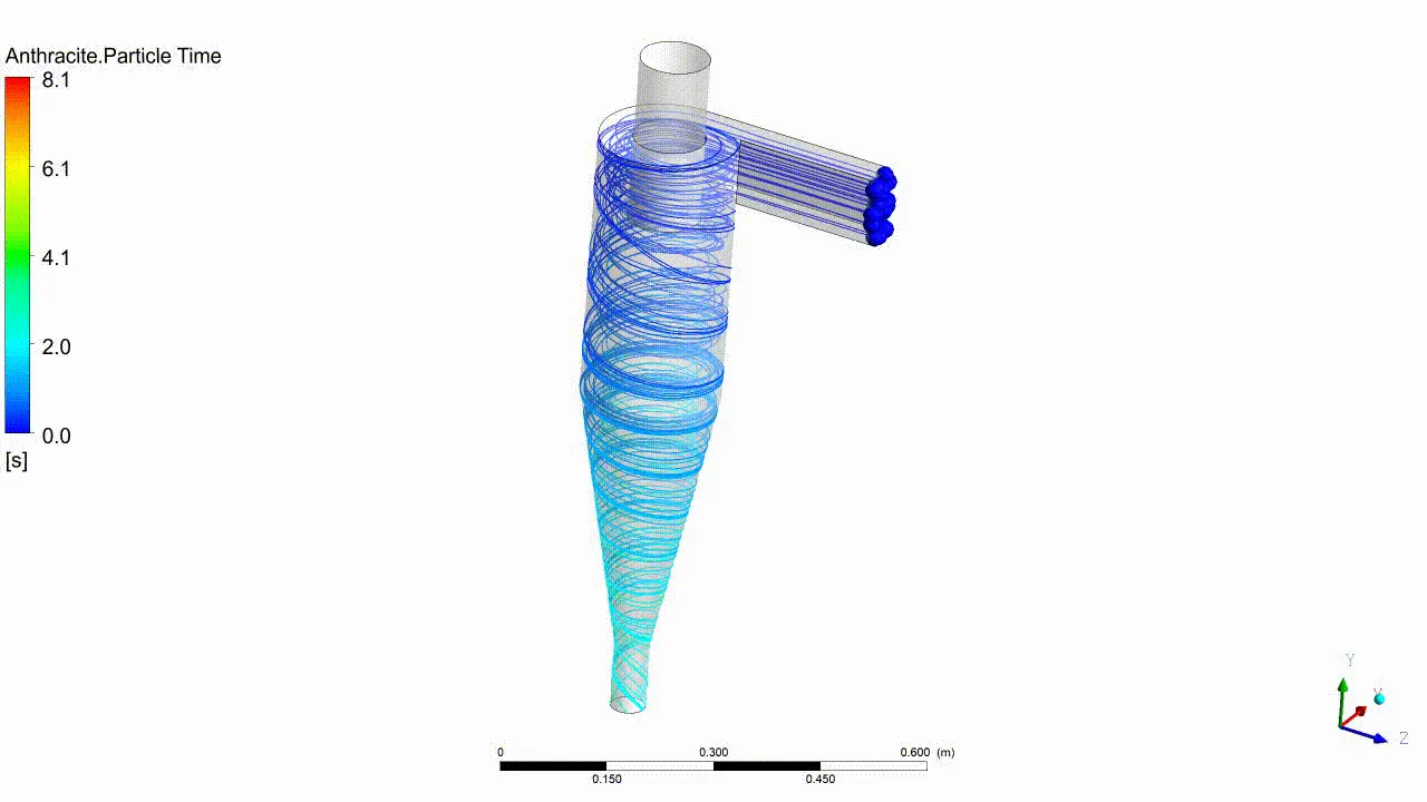
Animation showing the particle Seperation
Case 1 Series Data - (Varying the particle diameter)
| Particle Size [micron] | Pressure Drop [Pa] | Particle Track Started | Particle Escaped | Particle Trapped | Particle Incomplete Track |
| 1 | 20.29 | 172 | 39 | 36 | 97 |
| 2 | 20.29 | 172 | 33 | 135 | 4 |
| 3 | 20.29 | 172 | 20 | 148 | 4 |
| 4 | 20.29 | 172 | 6 | 163 | 3 |
| 5 | 20.29 | 172 | 0 | 169 | 3 |
Case 2 Series Data - (Varying the particle Velocity)
| Particle Velocity [m/s] | Pressure Drop [Pa] | Particle Track Started | Particle Escaped | Particle Trapped | Particle Incomplete Track |
| 1 | 1.69 | 172 | 4 | 17 | 151 |
| 2 | 8.71 | 172 | 4 | 6 | 162 |
| 3 | 20.29 | 172 | 0 | 169 | 3 |
| 4 | 37.02 | 172 | 0 | 171 | 1 |
| 5 | 58.23 | 172 | 0 | 172 | 0 |
It is quite evident from the above data gatherd from simulation results that pressure drop is very much related to the inlet velocity. In the first series of study, there was constant pressure drop.
Keeping the velocity constant, Increase in particle size improved efficiency of the cyclone seperator.
As we increase the inlet speed, the pressure drop also increases.
With increase in inlet velocity, for increased particle size, the cyclone seperator efficiency is greater.
Reference
Jolius, G., Chuah, L. A., Thomas, C., Yaw, T. S., & Fakhru’l-Razi, A. (2006). Evaluation on empirical models for the prediction of cyclone efficiency.