Week 12 Challenge
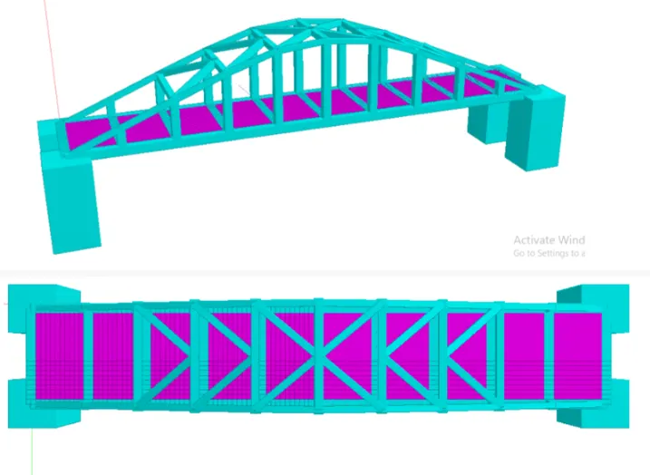
Aim: To calculate Barge Impact load of the Panamax vessel on the bridge designed and shown in figure below.
Data Provided:
- Dead weight = 52500 DWT
- No of containers = 4500 containers
- Each containers = 6.1TEU
- Speed of the barge = 60km/hr
- Length of the vessel = 294m
- Span of the bridge = 12.0m
- width = 7.0m
- Pier size = 2.5 x 2.5 m
- Rise of bridge = 5.0m
- Deck slab = 500mm thick
- Cross girder = 0.75 x 1.8 m
- Hydrodynamic coefficient = 1.25
Theory :
Bridges crossing navigable channels of rivers, creeks and canal as well as shipping channels in port areas and open areas can be provided with navigable spans. Navigation spans shall be specifically identified and marked to direct waterway traffic below them.
1. The following should be decided based on the classification of waterways as per Inland waterways Authority of India (IWAI) or the concerned ports or shipping authorities:
- Span arrangements
- Horizontal clearances between the inner face of piers within thw width of navigation channel.
- Vertical clearances above the air-draft of the ships/ barges upto soffit of deck
- Minimum depth of water in the channel below the maximum laden draft of barges.
2. Bridge components located in a navigable channels of rivers and canals shall be designed for barge impact force due to possibilityof barge accidentally colliding with the structure.
3. For bridges located in sea and waterways under control of ports
Bridge components should be designed for vessel collision forces.
- Ship / barge details can be obtained fromconcerned authority.
- Specialist literature may be referred for magnitudes of design forces and appropriate design solutions
4. Design objectives of the bridges:
- To minimise the risk of structural failure of bridge component due to collision with a plying barge in a cost-effective manner.
- Reduce the risk of damage to the barge and environmental pollution
5. Localised repairable damage of substructure and super structure components is permitted provided that
- Damaged structural components can be inspected and repaired in a relatively cost effective manner not involving detailed investigation
- Sufficient ductility and redundancy exist in the remaining structure to prevent consequential progressive collapse in the event of impact.
Procedure
Calculation of barge imoact load:
1. Barge Collision energy KE = 500 CH W V^2
where,
KE = Barge collision energy in N-m
W = Barge displacement tonnage in T
V = Barge impact speed in m/s
CH = Hydrodynamic coefficient
- CH = 1.05 to 1.25 for barges depending on under keel clearance available
- CH = 1.05 if under keel clearance > 0.5 x draft
- CH = 1.25 if under keel clearance < 0.1 x draft
Therefore,
KE = 500 x 1.24 x 52500 x (60 x 1000/ 60 x 60)^2 = 9.041 x 10^9 Nm
2. Barge damage depth aB = 3100 ((1+1.3 x 10^-7 KE )^0.5 -1) in mm
Barge damage depth aB = 3100 ((1+1.3 x 10^-7 x 9.041 x 10^9 )^0.5 -1) = 103.22 x 10^3 mm
3. Barge collision impact force PB shall be determined based on the following equations
For aB < 100 mm, PB = 6 x 10^4 aB in N
For aB >= 100 mm, PB = 6 x 10^6 +1600 aB in N
Here since aB>= 100mm,
Barge collision impact force PB= 6 x 10^6 + 1600 x (103.22 x 10^3) = 171.8 x 10^6 N
Uniform force = PB / length of bridge = 171880 / 12 = 14323 kN/m
Designing in StaadPro:
Modelling
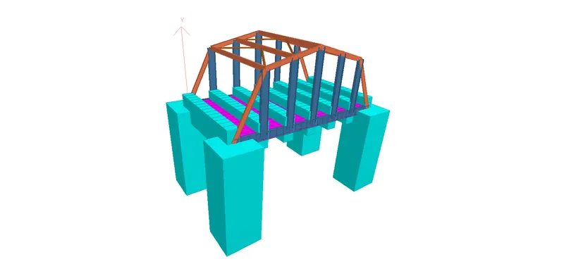
We create the nodes and as per given data, the pier and deck is created as under showing the Rise of bridge = 5m but we assume height of pier as 7m, span = 12m and width = 7m
Creating Truss bridge model.
- Create the first node using the cordinate.
- Now we need to create first cross beam of bridge.
- For that we select the first node using node cursor and copy it in Z direction upto 7 meter (Width of the bridge Given) using translational repeat command.
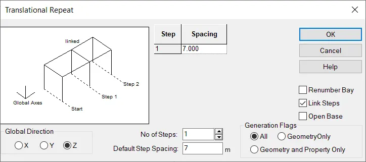
- In translational repeat option select direction as Z and spacing should be 7m and also click link steps option to connect both the node then click on Ok to creat the cross beam.
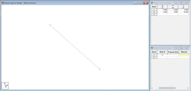
- Span of the bridge is given 12 meter.
- We select that beam using beam cursor and copy it in X direction using translational repeat option.
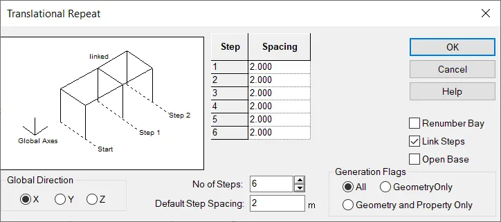
- In translational repeat option select direction as X and spacing should be 2 meter and No of steps 6 nos.
- Also click on link steps to connect all the cross beam.
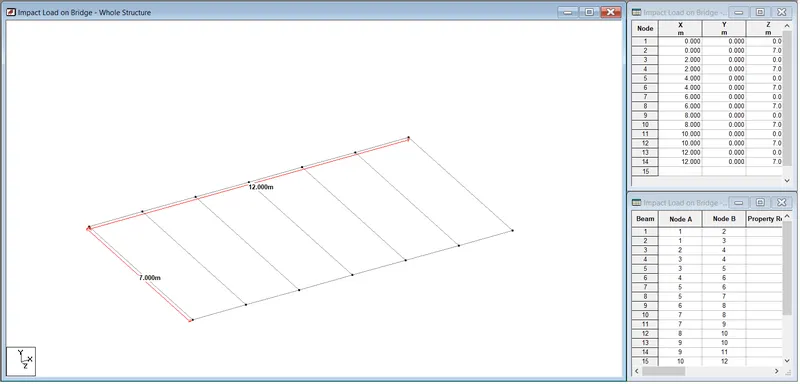
- Then Creating pier in model
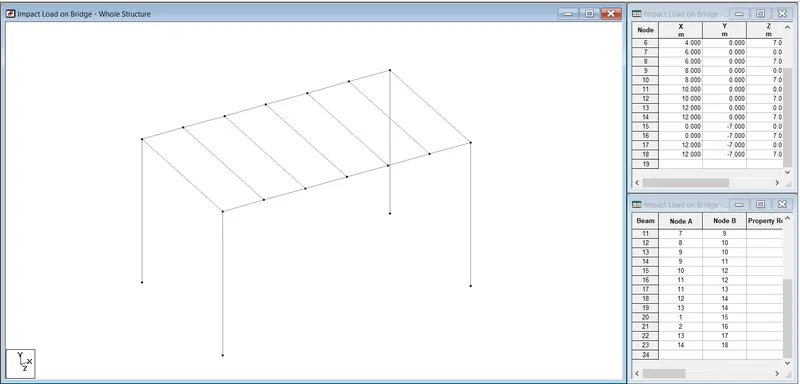
- For creating pier fisrt select all four ending node of cross girder and copy them in Y direction using translational repeat option.
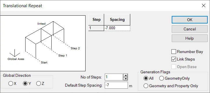
- In Translational repeat option select direction as Y and spacing should be -7 meter assumption (because we are copying node in inverse direction)
- No of step should be 1 and aslo select link steps option to connect both the node then click on OK to create.
- Creating vertical member.
- For that select both side node of middle cross beam and copy them in Y using translational repeat option upto 5 meter.
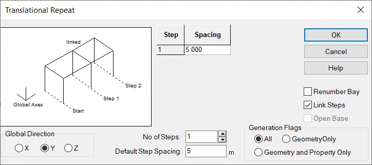
- In translational repeat option select direction as Y and spacing is 5 meter and also click on link steps to connect both the node than click on OK to create.
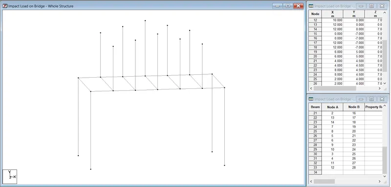
- We repeat same procedure for all cross beam
- We put variation in spacing.
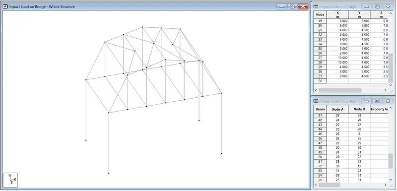
- After that connect all the node using add beam option.
- For that we go to geomertry select add beam option then connect all the node like wise shown in question.
- Creating deck slab for bridge.
- Select first node on crossbeam and copy them in X direction upto 0.5 meter using translational repeat command.
- Again select both the node and copy it in Z direction upto 0.5 meter using translational repeat command.
- After that adding plate to that node which we created for that go to geometry option in that select add plate option and connect all 4 nodes.
- Hence one plate is created.
- Then select that plate using plate cursor and copy it in X direction using translational reapeat option.
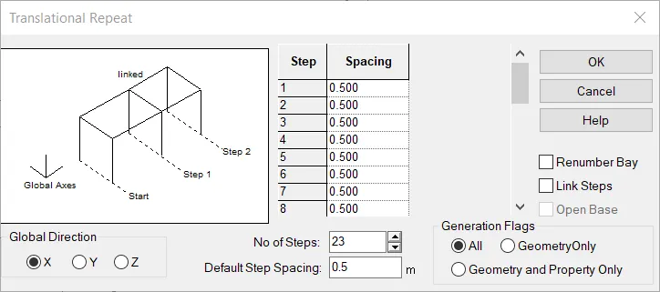
- In translational repeat option select direction as X and spacing should be 0.5 Meter.
- And no of step is 23 nos, length of the bridge is 12 m so 12/0.5 = 24 , 24-1= 23 nos then click on OK to create.
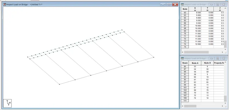
- Again select all the plate using plate cursor and copy them in Z direction using translational repeat option.
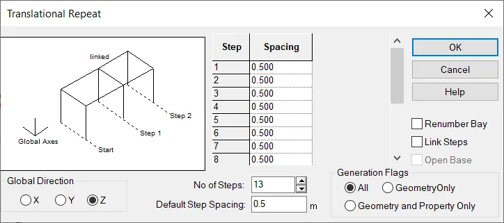
- In above window select direction as Z and spacing is 0.5.
- Width of bridge is given 7 meter so no. of step should be 13 nos, 7/0.5=14, 14-1= 13 nos.
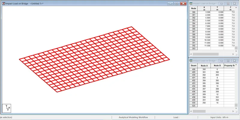
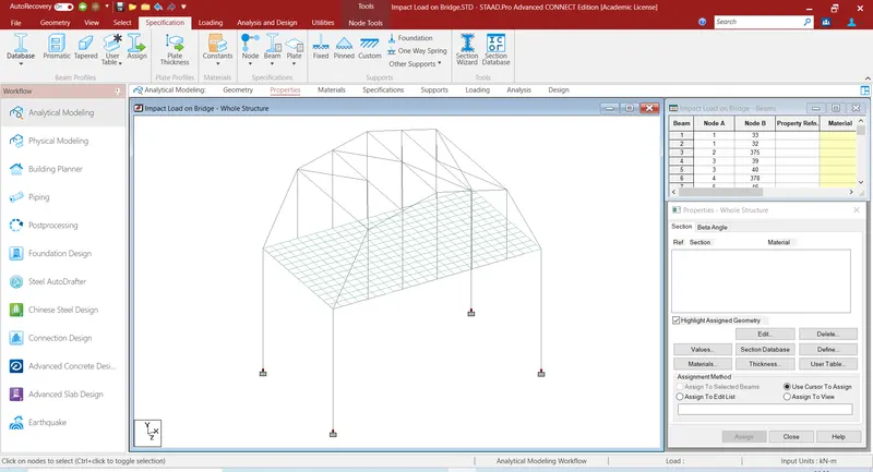
- Adding support to the piers.
- For adding support first go to specification then select fixed support option.
- Then one window will open in that window click on add option.
- After that suppot window will open.
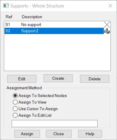
- In above window click on support 2 option and select all button node of all the piers and then click on assign button to add the support.
- Hence support is assign to all the piers.
Specifications
- For assigning property we go to specification then click on prismatic option then property window will open.
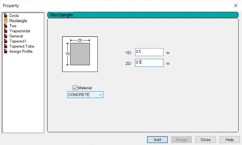
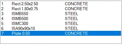
- Insert the value of piers as 2.5 X 2.5 M which is given in question then click on add option.
- After select all the pier using beam cursor and assign this property to it.
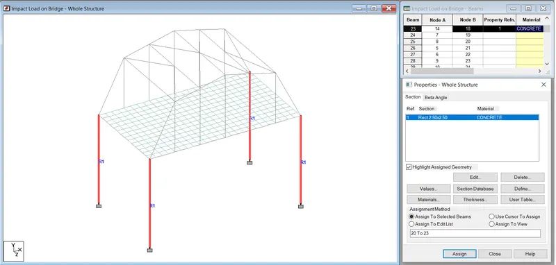
- Adding property to the crossgirder.
- We repeat same procedure as above.
- In property window put value of cossgirder as 0.75 X 1.8 metre as also mentioned in question.
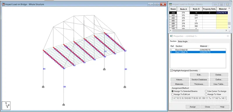
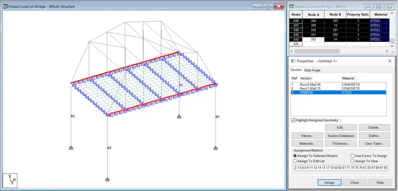
- For main girder assume S shape property as ISMB 550
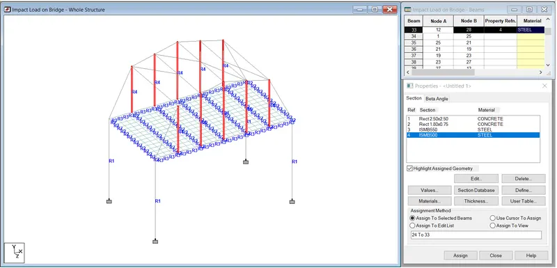
- For vertical component of bridge truss assume property as ISMB 500.
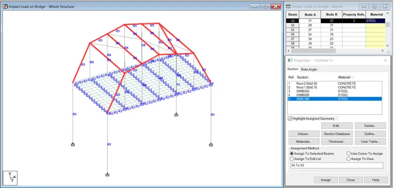
- For top chord and strut component of bridge assume property as ISMC 300
- For top lateral bracing assume angle property as IAS 90X90X10
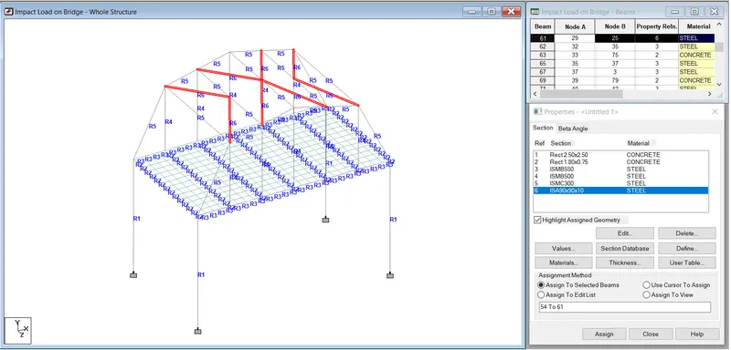
- Adding propery to deckslab.
- For that go to specification then click on plate thickness after that plate property window will open.
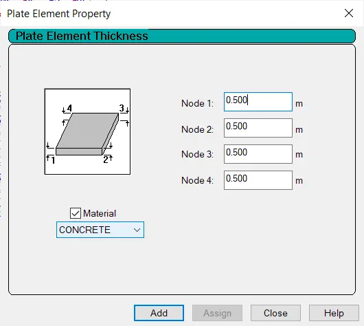
- Assign 500 mm thickness of deckslab then click on add.
- Select the deckslab using plate cursor and assign this property to it.
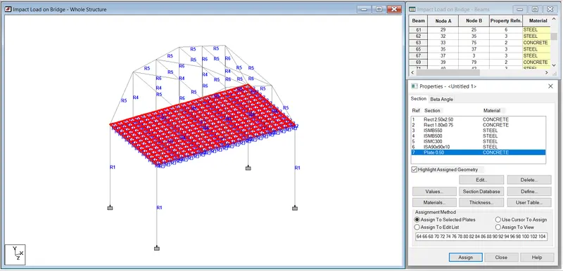
3D Model
Loading
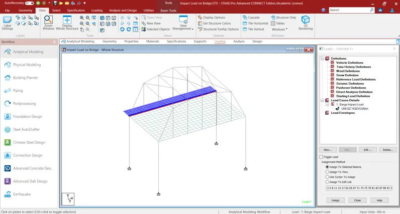
- For assigning barge impact loading to the sturcture go to loading option.
- In right side of the window load & defination window will shown.
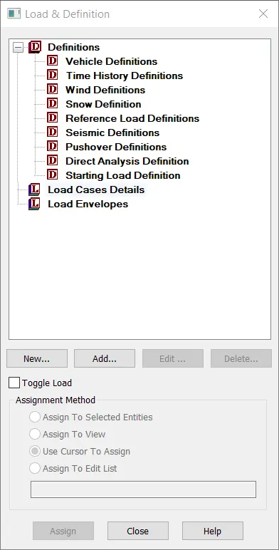
- In above window create load case 1 as barge impact load.
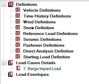
- Select that load which we created and then click on add option.
- After that this window will open.
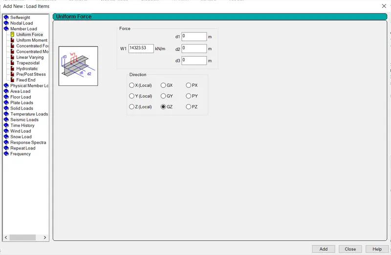
- In above window select member load in that select uniform force and insert that W1 as 14323.53 kN/m (Barge Impact force as calcualted above) and also select direction as GY then click on add option.
- Then select that load and assign to the structure.
Analysis
- Go to analysis and design option than click on run analysis option.
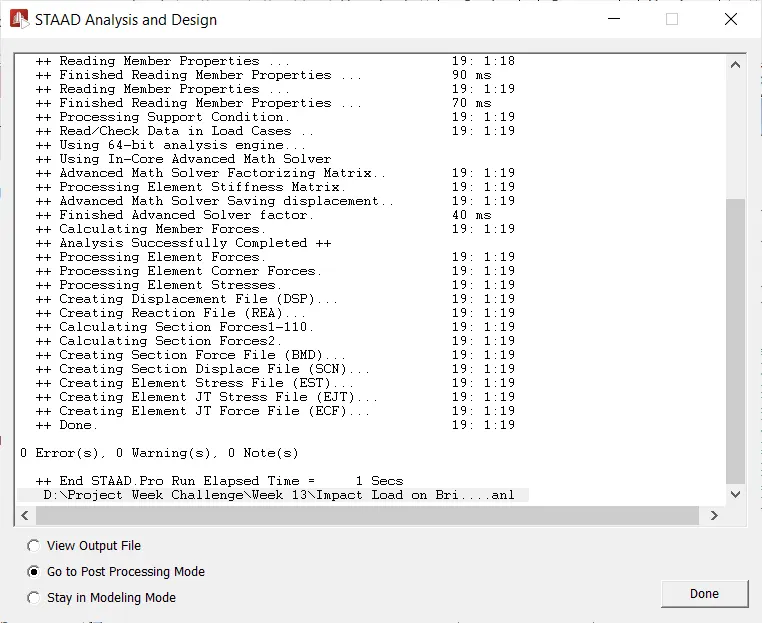
- To view the result select post processing mode in above window and click on done option.
Results
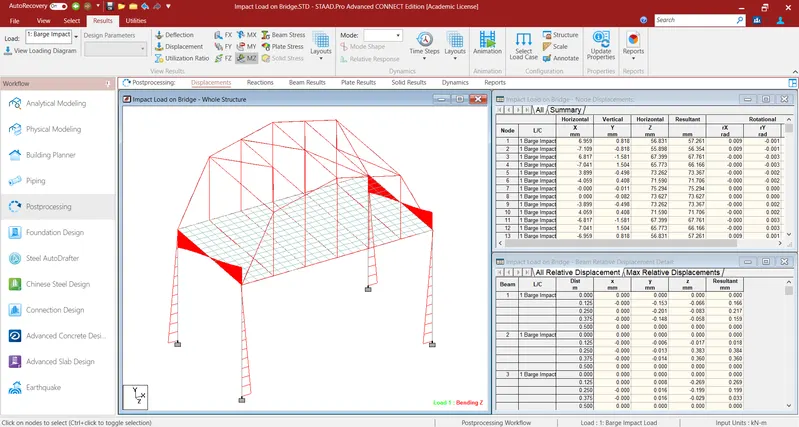
A) Bending moment diagram
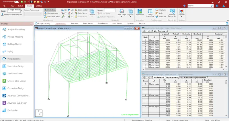
B) Deflection diagram
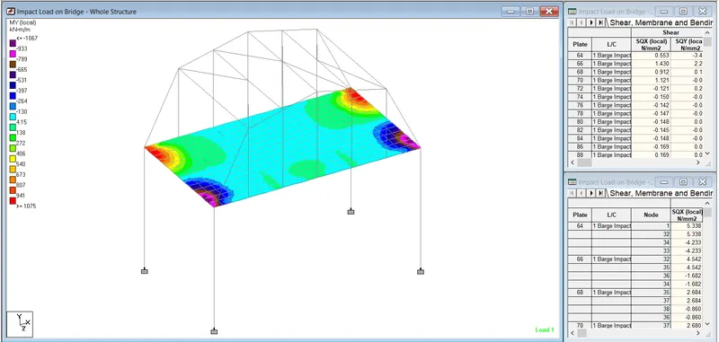
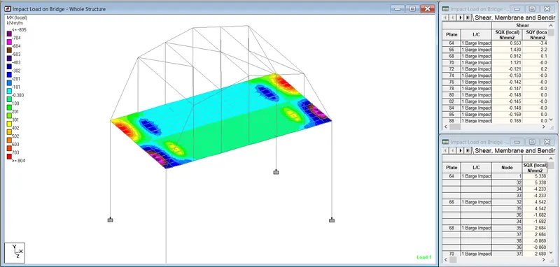
C) Plate stress in MY and MX