Project 2
Aim
- The primary aim of this challenge is to arrive at optimum bearing articulation using two bearing and one bearing system.
- To model the bridge as per the given dimension and apply all the load combinations on it. Then to analyze the results.
- The substructure such as pier need to be checked by modelling the structure in ASBD software and to check the efficient section by optimiziing the size of the section.
- Then to check all the needful checks as per the relevant code IRC 112 and to the present the detailing as per the calculation.
Bearing Articulation
General:
Bridges are subjected to a variety of influences that cause displacement of the bridge deck and its supports. If these movements are resisted, forces will be generated within the structure. To control the development of restraint forces it has become normal practice to place the bridge deck on support bearings which allow some freedom of relative movement between the deck and supports. The arrangement of supports and freedoms of movement is known as the ‘articulation’.
Sources of Movement
Sources of movement include:
- temperature change (uniform and differential)
- shrinkage and creep of concrete
- dead load deflections/rotations
- traffic load deflections/rotations
- deflections/rotations due to horizontal loads (braking, traction, skidding, wind loads)
- settlement of supports
- earth pressure on abutment walls
- deflections of slender piers
- vehicular collision
- seismic effects
Basic principles for good articulation
A bridge can be articulated in one of a number of ways. The following principles should generally be followed:
Minimise the number of bearings and joints by the use of continuous spans.
The fewer the number of deck joints, the fewer the number of bearings and the less the opportunity for water to leak through and create potential durability problems. (The ultimate expression of this principle is to use ‘integral bridges’.)
Proportion the spans and detail the superstructure to ensure that uplift does not occur at a bearing under any load combination.
Choose an arrangement that provides simple restraint against longitudinal loads.
Provide longitudinal fixity at only one support, unless the supports are flexible enough to allow sharing of longitudinal loads.
Provide only one lateral restraint at each support, unless the supports are flexible.
As well as unequal sharing of reactions, restrained bearings may restrain rotation of the beams about their longitudinal axes,
thus inducing extra forces on the bearings.
Anticipate the need during construction for temporary lateral restraint of individual girders
Each girder, or pair of braced girders, will require temporary restraint. Choose the location of the permanent restraint to facilitate the temporary restraint.
Consider at which end the bridge should be fixed
In highway bridges, take account of the geometry and drainage provisions, to minimise the exposure of the major expansion
joint to surface water flow. Rail bridges are ideally fixed (subject to abutment capacity) such that the beams are in tension under the dominant longitudinal force for the prevailing direction of traffic. On continuous structures, centre fixing may be an option.
Try to choose as the fixed or guided bearings those with the largest minimum vertical loads coexistent with the maximum horizontal load.
Guided or fixed bearings with low minimum vertical loads are likely to require special designs and may be more expensive. Alternatively, use a separate guided bearing that does not carry vertical load.
Consider the effect of fabrication tolerances
Consideration should be given to making an allowance for fabrication tolerances in calculating design values of positions and
translations for the bearings - including systematic growth/ shrinkage of steelwork.
Avoid buried movement joints on steel bridges (unless spans are very small or there is an integral configuration).
Larger rotations/deflections on steel bridges (compared to concrete bridges) can lead to early joint failures.
As bearings and the expansion joints introduce a maintenance liability, it is good practice to limit the number of bearings required and to minimise the movement to be accommodated by an expansion joint. Spans should be arranged so as to avoid uplift at bearings positions (it is a very complex and costly matter to provide restraint against uplift in a bearing), particularly when dealing with skewed structures.
The designer should avoid locking in forces that would hinder bearing replacement. Restraint against longitudinal forces should be provided at one support, with guided restraints aligned to allow movement at the other supports. Similarly, restraint against transverse forces should be provided at only one bearings at each support. The construction sequence of the structure should also be considered, to establish the permanent displacements.
The articulation scheme that the designer chooses should be shown on the drawings and will form the basis of a bearing schedule.
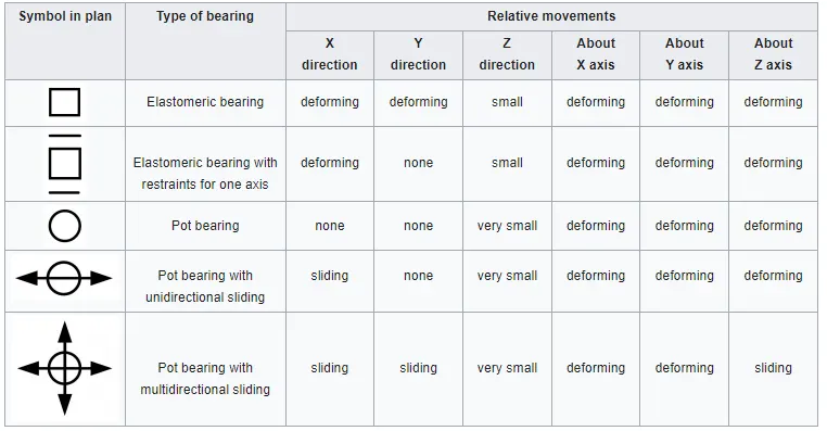
- Bearing articulation using 2 bearings:-
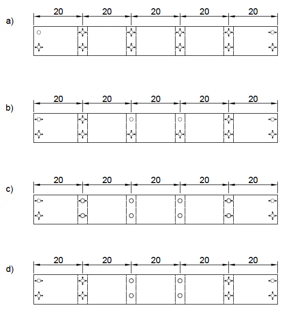
- The superstructure is of 5 span bridge with length of spans as 20m each.
- The articulation for the bearing of the continues structure is as follows.
- There are four possible arrangements.
- a) may be used if longitudinal loads can be resisted at the abutment
- this leads to the largest bearing movements (at the far end)
- intermediate guided bearing(s) are needed if the deck cannot span laterally between abutments
b) reduces the maximum movement compared to (a)
- a strong pier is required at the fixed bearing to resist the longitudinal loads.
- the deck acts in plan as a two-span beam.
c) If the pier columns are flexible laterally, each bearing may be guided; if the central columns are strong enough, they may provide the longitudinal restraint, as in (b).
d) If the central piers are tall and flexible, they may share in providing longitudinal restraint.
Note that in (c) and (d) the columns are restrained transversely at the top by the deck.
- The articulation for the bearing of the continues structure is as follows.
- Bearing articulation using 1 bearings:-
- a) may be used if longitudinal loads can be resisted at the abutment
- b) reduced maximum movement
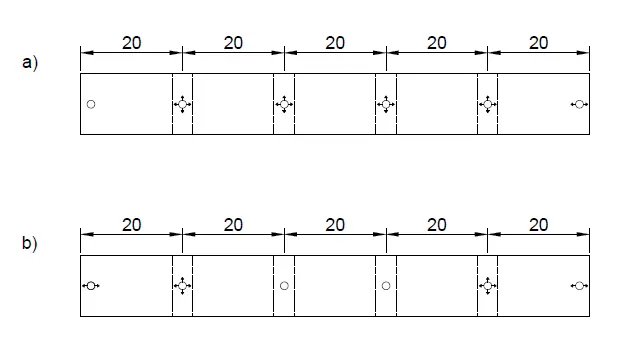
- For this Modelling, (a) shall be used
- STAAD Model
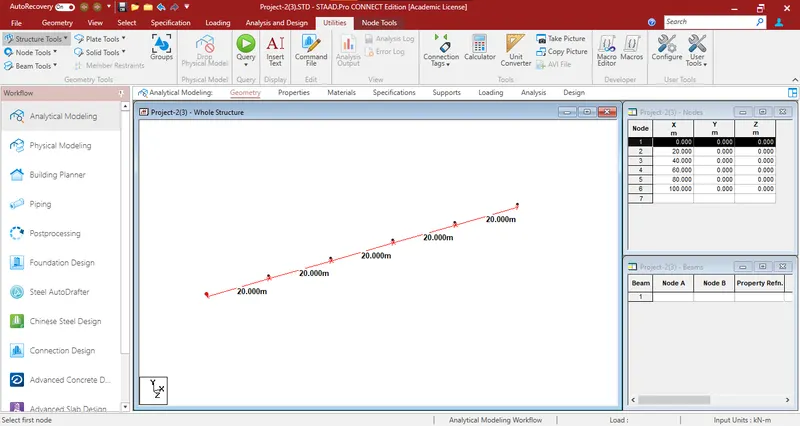
- The nodes for the pier were created.
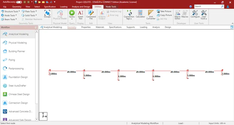
- The piers and abutments were created as per the given dimension.
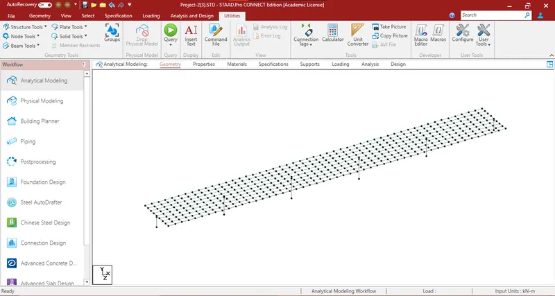
- The Deck was created using plate members.
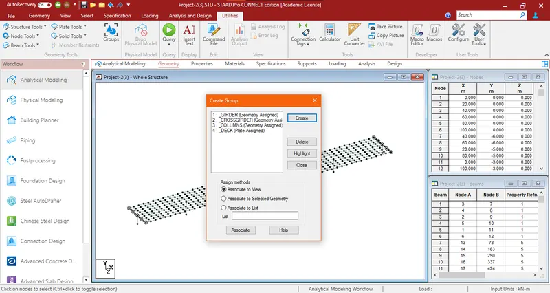
- Groups were created and members assigned.
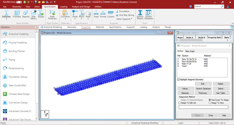
- Properties were created and Members assigned.
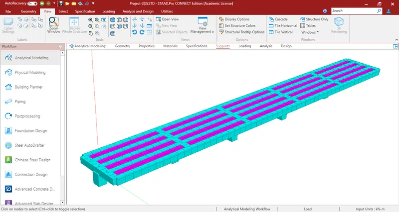
- A 3D Rendered Image is shown below:
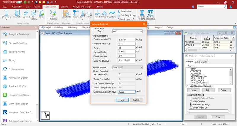
- Material was created for M40 Grade Concrete and assigned:
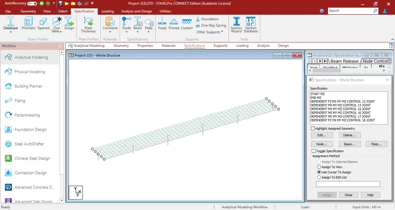
- Specification for Nodes (Bearing Articulation) and Beams were assigned.
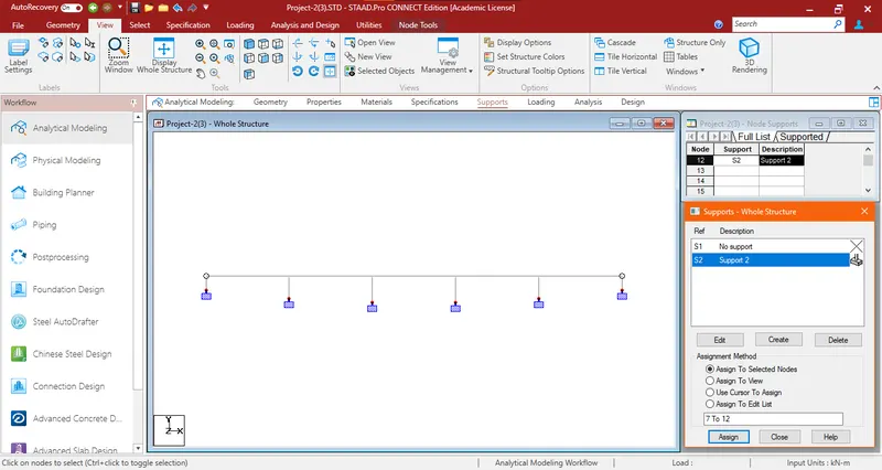
- Fixed supports were assigned to the model.
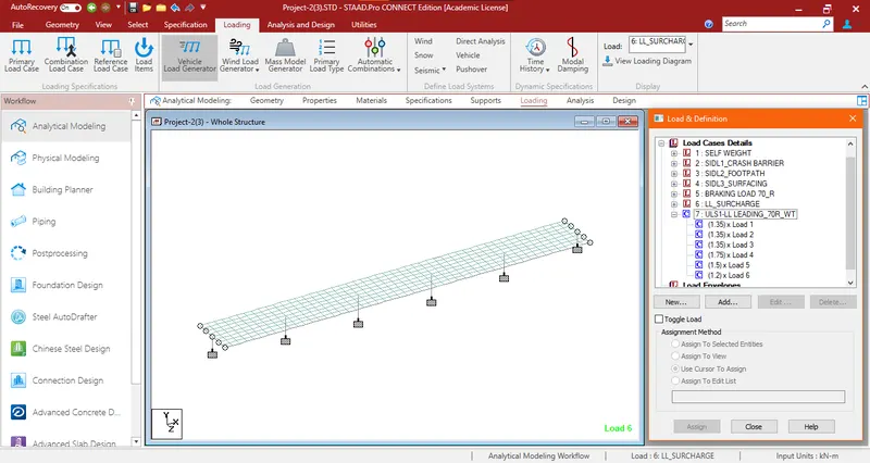
- Different load criterias were calculated and assigned to the structure.
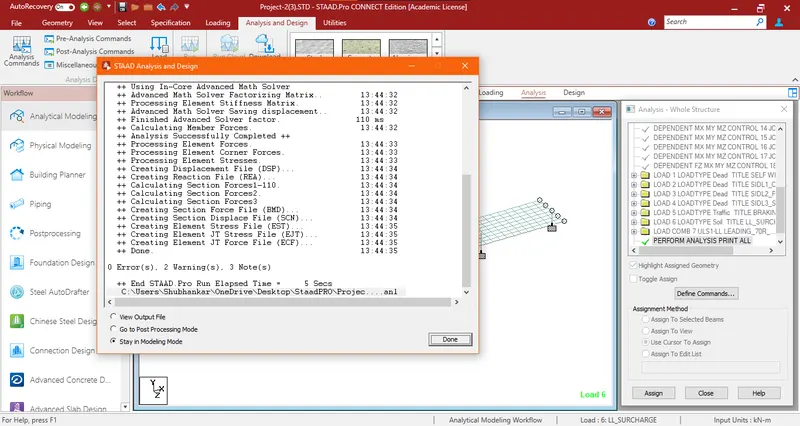
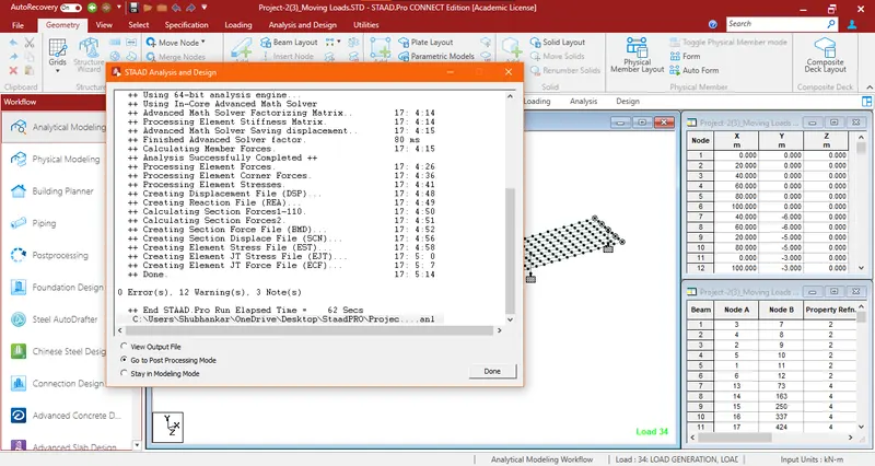
- The model was analyzed and Zero Errors were found.
- RESULT & OUTPUT
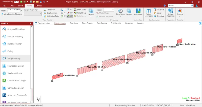
- Max BM Mz for the ULS Combination:
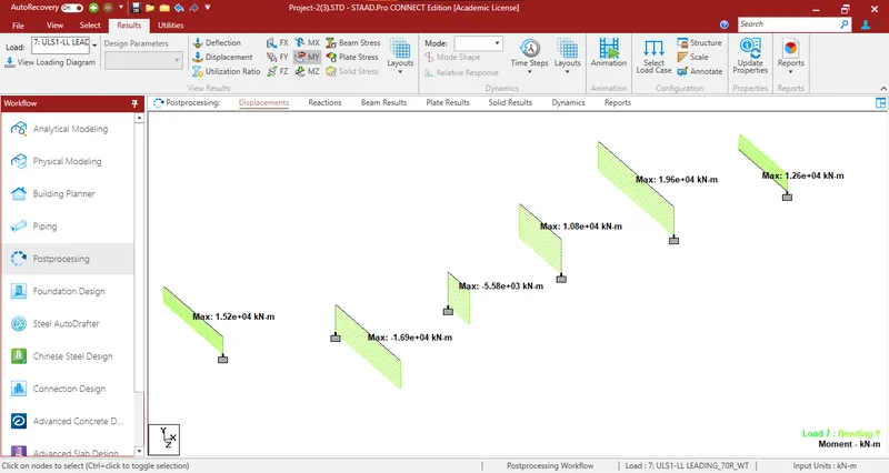
- Max BM My for the ULS Combination:
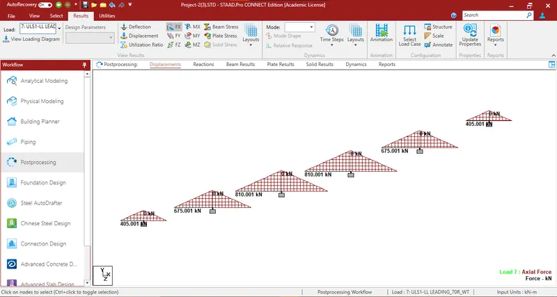
- Axial force for the ULS Combination:
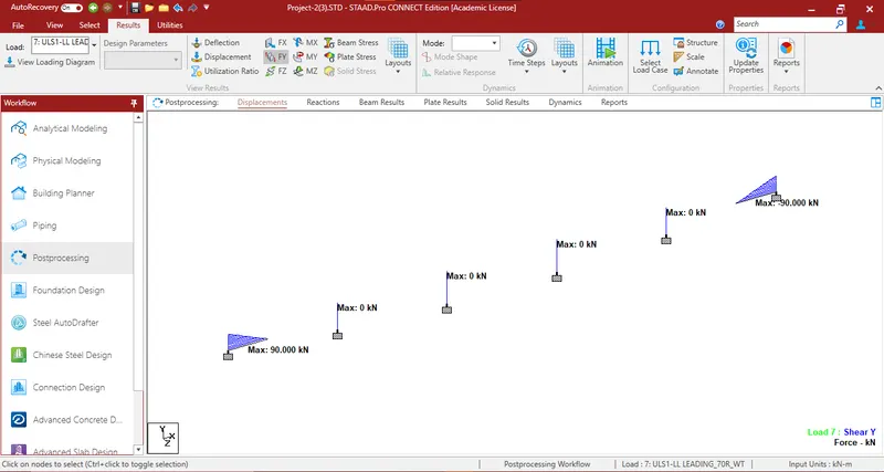
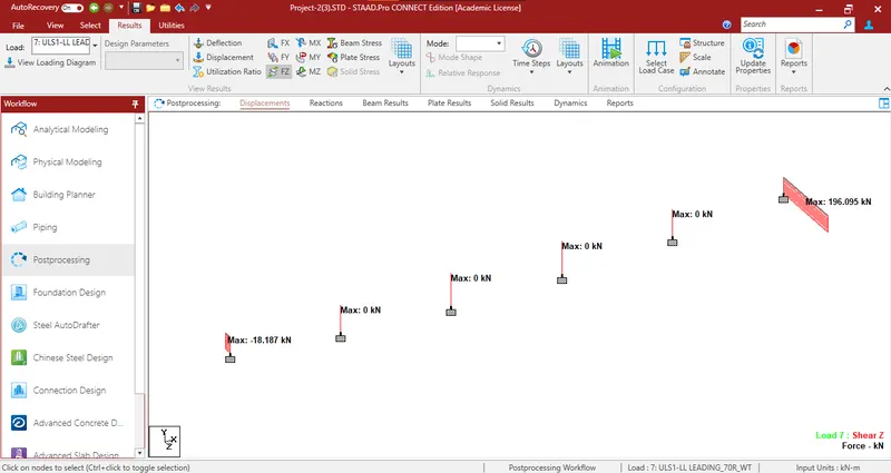
- Shear Force for the ULS Combination:
- The above results are tabulated below:
-
Load Case Structure Bending Moment (kNm)
(Longitudinal Mz)Bending Moment (kNm)
(Transverse My)Axial Force (kN) Shear Force
(kN)7-ULS-LL Leading_70R_WT Substructure 445000 19600 810 197
- Another Model was created to apply only live load i.e. vehicular load Class 70R-Wheeled.
- Generated loads for Class 70R-Wheeled.
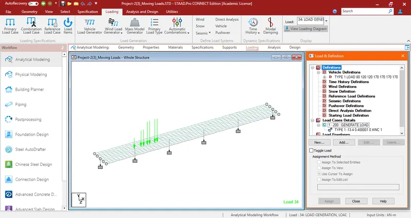
- The model was analyzed and Zero Errors were found.
- RESULT & OUTPUT
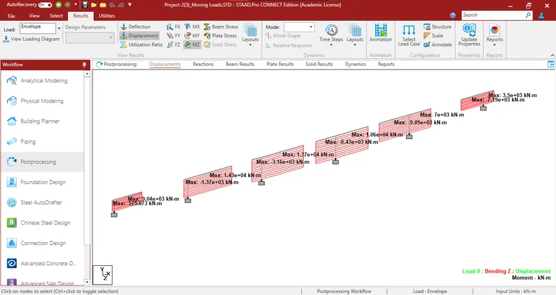
- Max BM Mz for the Maximum Generated Load:
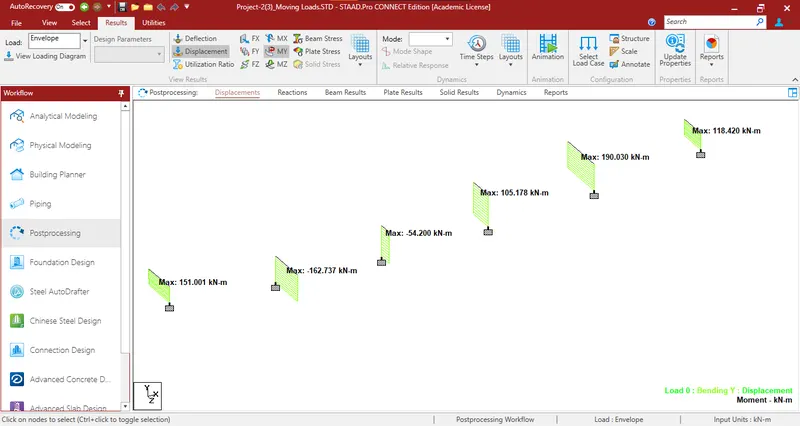
- Max BM My for the Maximum Generated Load:
- Axial force
-
StaadPro shows no values for Axial Force which shall therefore be manually calculated as shown below:
Total Load = 100 tonnes (As per IRC)
= 981 kN
Half of the above value shall be taken as maximum at an instant, therefore = 491 kN
For Ultimate Limit State a further factor of 1.5 shall be multipied
Therefore, Axial Force = 491 x 1.5 = 736.5 kN
- The above results are tabulated below:
Load Case Structure Bending Moment (kNm)
(Longitudinal Mz)Bending Moment (kNm)
(Transverse My)Axial Force (kN) Shear Force
(kN)7-ULS-LL Leading_70R_WT Substructure 10540 190 736.5 260
The Summary of All Forces is Tabulated below:
| Load Combination | Live Load (70R-Wheeled) | Total Load | |||||||||||
| Load Case | Structure |
Mz (kNm) |
My (kNm) |
Shear Force (KN) | Axial Force (kN) |
Mz (kNm) |
My (kNm) |
Shear Force (KN) | Axial Force (kN) |
Mz (kNm) |
My (kNm) |
Axial Force (kN) |
Shear Force (kN) |
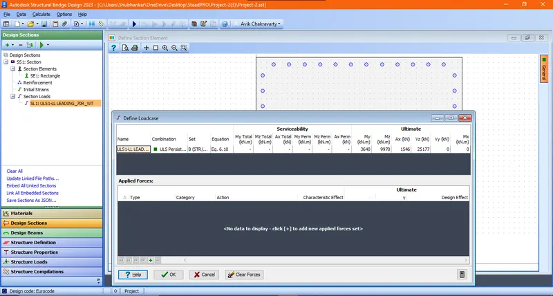
| 7:ULS1-LL LEADING_70R_WT | Substructure | 445000 | 19600 | 197 | 810 | 10540 | 190 | 260 | 736.5 | 455540 | 19790 | 1546 | 457 |
Design of Fixed Rectangular column using ASBD software
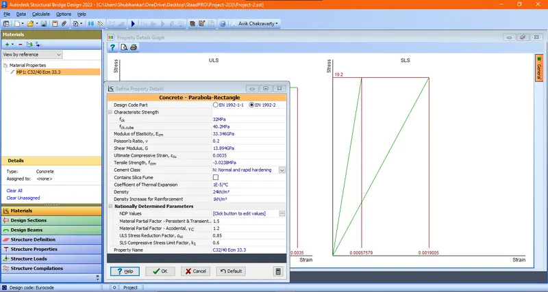
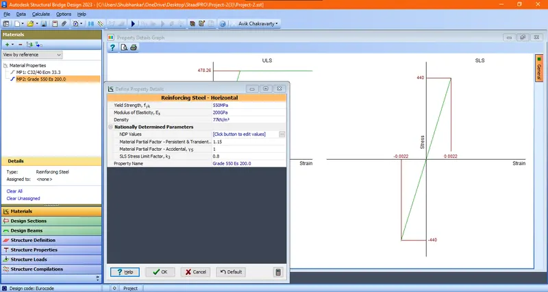
First of all defining the material properties in ASBD software.
- Concrete Properties- Taking Characterstic Strength as 40MPa
- Steel Properties - Taking Characterstic Strength as 550MPa
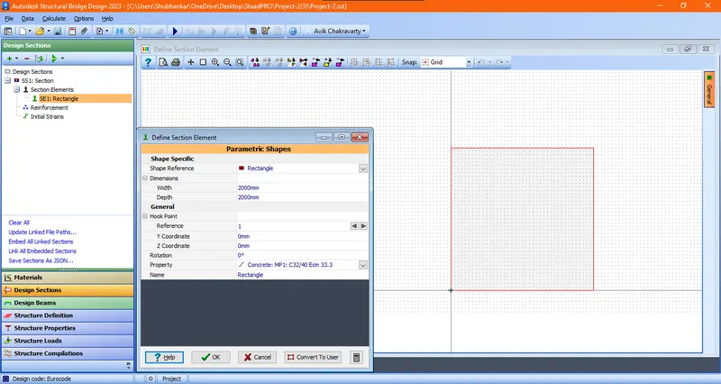
- Defining Section properties as Pier size - 2m x 2m
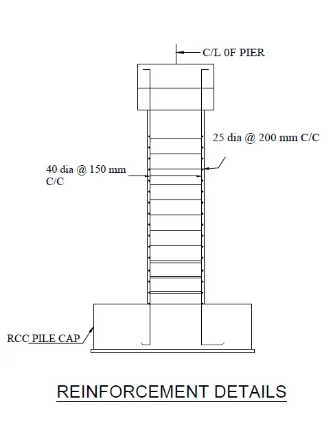
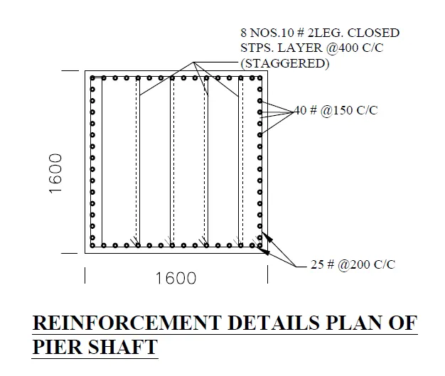
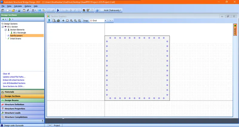
- Providing reinforcement of 40 mm dia at 150 mm spacing in all the faces with 50 mm cover.
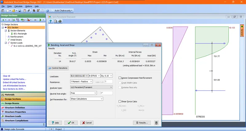
- Defining the load details as per the staad model.
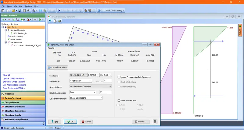
- The section is safe.
- Again considering & optimizing the section to 1.6m x 1.6m. Then also the structure is safe.
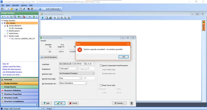
- Again considering & optimizing the section to 1.2m x 1.2m and the structure is not safe.
- So the size of the pier as 1.6m x 1.6m has been taken.
Details Calculations & Checks
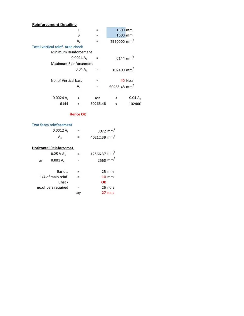
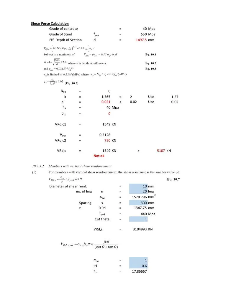
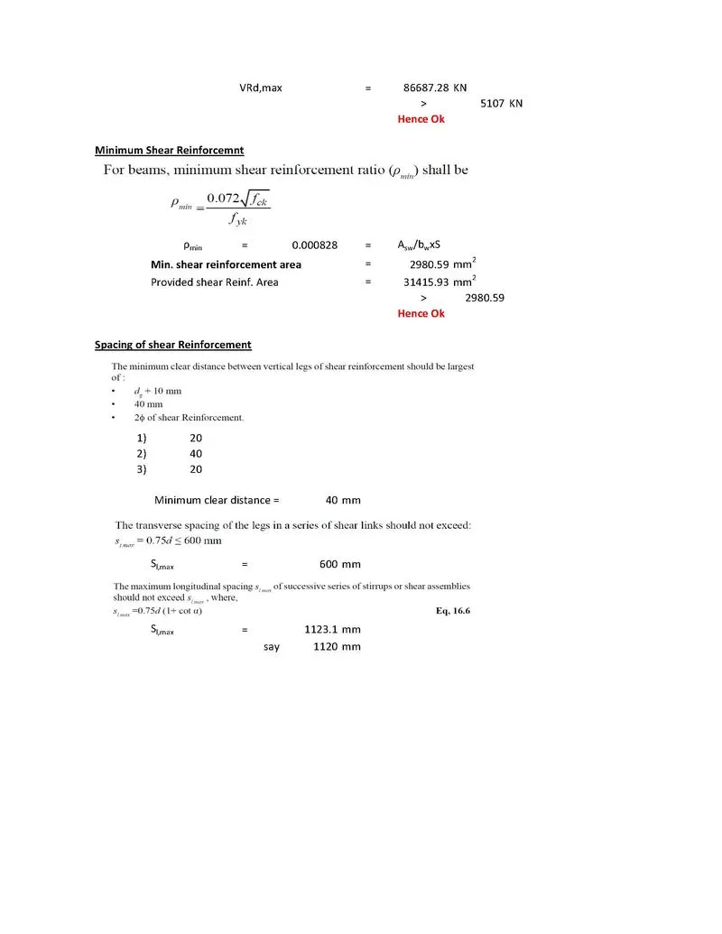
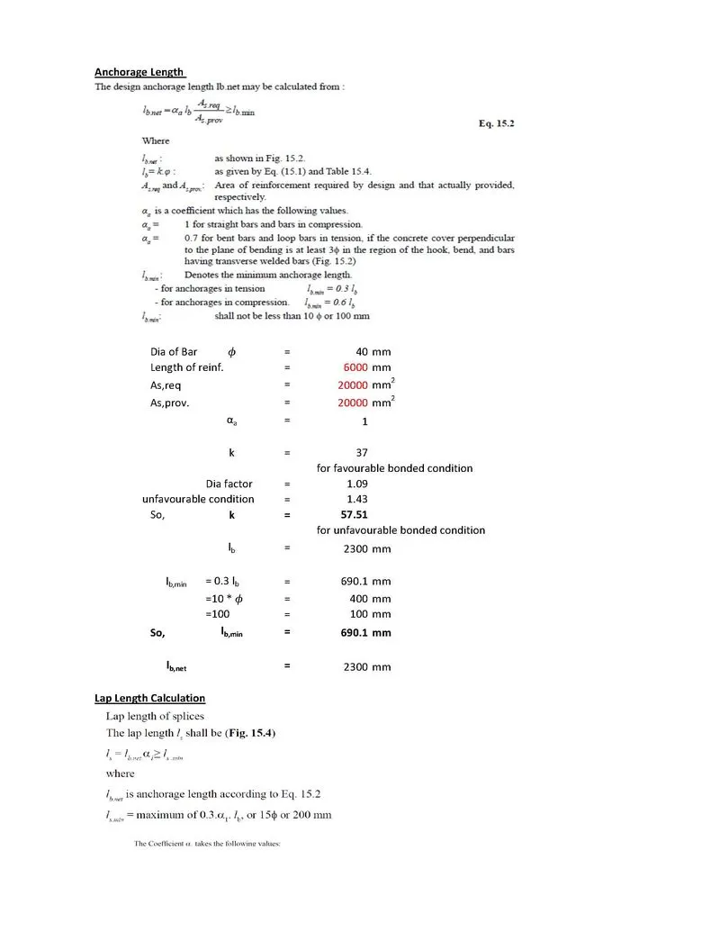
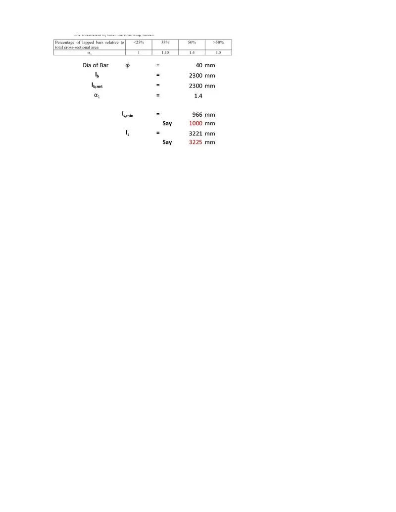
- Reinforcement Detailing
- The reinforcement detailing of the pier is as below.